

Eternus DX80 S2, DX90 S2 User Manual

This page is intentionally left blank.

Preface
Fujitsu would like to thank you for purchasing our ETERNUS DX80 S2/DX90 S2 Disk storage
system.
The ETERNUS DX80 S2/DX90 S2 Disk storage system is designed to be connected to Fujitsu
(PRIMEQUEST or PRIMERGY) or non-Fujitsu servers.
This guide describes the environmental requirements that are necessary to install and use the
ETERNUS DX80 S2/DX90 S2 Disk storage system.
This guide is intended for use of ETERNUS DX80 S2/DX90 S2 Disk storage system in regions
other than Japan.
Please carefully review the information outlined in this manual.
Third Edition
September 2011
Microsoft, Windows, Windows Server, and Internet Explorer are either registered trademarks or
trademarks of Microsoft Corporation in the United States and/or other countries.
Mozilla, Firefox, and the Mozilla and Firefox logos are trademarks or registered trademarks of the
Mozilla Foundation in the United States and other countries.
The company names, product names and service names mentioned in this document are registered trademarks or trademarks of their respective companies.
Copyright 2011 FUJITSU LIMITED
3
ETERNUS DX80 S2/DX90 S2 Disk storage system User’s Guide -Site Planning-
Copyright 2011 FUJITSU LIMITED P3AM-4822-03ENZ0

Organization
This document is composed of the following four chapters:
● Chapter 1 Hardware Configurations
This chapter describes the main components and the relative optional products that are
installed in the ETERNUS DX80 S2/DX90 S2 Disk storage system.
● Chapter 2 ETERNUS DX Disk Storage System Installation
This chapter describes the installation specifications, the installation environment, and the
power requirements.
● Chapter 3 Connections
This chapter describes the configuration for each interface to connect to the ETERNUS DX80
S2/DX90 S2 Disk storage system.
About this Manual
● Chapter 4 Rack and Optional Product Installation
This chapter describes the requirements for rack installation.
This chapter also describes the standard installation rules (installation locations and installation order) of the optional products before shipment from the factory when the optional products are purchased with the ETERNUS DX80 S2/DX90 S2 Disk storage system at the same
time.
Naming Conventions
■ Abbreviations used in this manual
• "ETERNUS DX Disk storage system" refers to the ETERNUS DX80 S2/DX90 S2 Disk
storage system.
• "CA" refers to the host interface module used in the ETERNUS DX Disk storage systems to
connect to the server.
• "Host Bus Adapter (HBA)" refers to the interface module normally used by the server to
connect to the ETERNUS DX Disk storage systems.
A "FC card", "LAN card", "Network Interface Card (NIC)", "Converged Network Adaptor
(CNA)", or "SAS card" may be used instead, depending on the server and interface.
• Trademark symbols such as ™ and ® are omitted in this document.
4
ETERNUS DX80 S2/DX90 S2 Disk storage system User’s Guide -Site Planning-
Copyright 2011 FUJITSU LIMITED P3AM-4822-03ENZ0
About this Manual
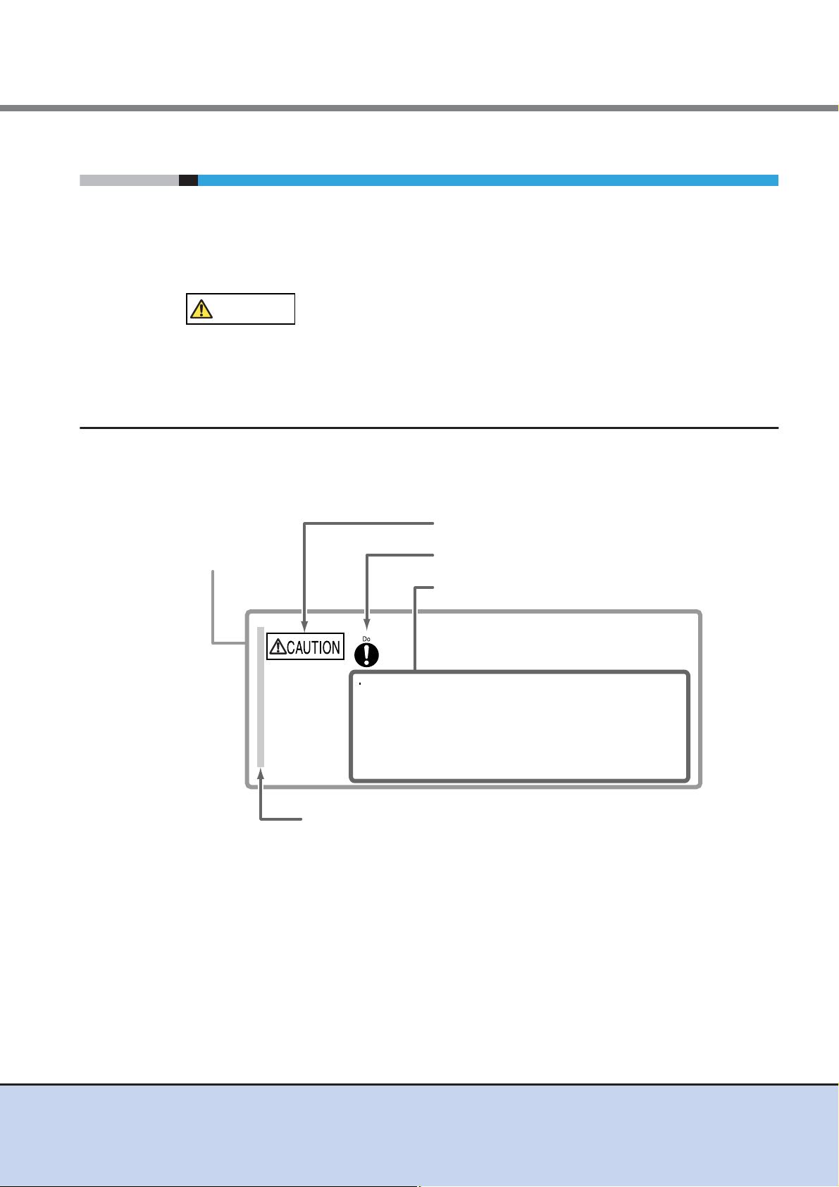
CAUTION
Warning Level Indicator
Warning Type Indicator
Warning Details
To avoid damaging the ETERNUS DX Disk storage system,
pay attention to the following points when cleaning the ETERNUS DX
Disk storage system:
- Make sure to disconnect the power when cleaning.
- Be careful that no liquid seeps into the ETERNUS DX Disk storage
system when using cleaners, etc.
- Do not use alcohol or other solvents to clean the ETERNUS DX Disk
storage system.
Warning Layout Ribbon
Example Warning
Warning Notations
Warning signs are shown throughout this manual in order to prevent injury to the user and/or
material damage. These signs are composed of a symbol and a message describing the recommended level of caution. The following explains the symbol, its level of caution, and its meaning
as used in this manual.
This symbol indicates the possibility of minor or moderate personal
injury, as well as damage to the ETERNUS DX Disk storage system
and/or to other users and their property, if the ETERNUS DX Disk
storage system is not used properly.
How Warnings are Presented in this Manual
A message is written beside the symbol indicating the caution level. This message is marked
with a vertical ribbon in the left margin, to distinguish this warning from ordinary descriptions.
An example is shown here.
ETERNUS DX80 S2/DX90 S2 Disk storage system User’s Guide -Site Planning-
Copyright 2011 FUJITSU LIMITED P3AM-4822-03ENZ0
5

Table of Contents
Chapter 1 Hardware Configurations ......................................................11
1.1 Controller Enclosure ......................................................................................... 11
1.1.1 Controllers ................................................................................................................................. 15
1.1.2 Power Supply Units ................................................................................................................... 17
1.2 Drive Enclosures .............................................................................................. 17
1.2.1 I/O Modules ............................................................................................................................... 21
1.2.2 Power Supply Units ................................................................................................................... 22
1.3 Enclosure Connection Path .............................................................................. 22
1.4 Drives ............................................................................................................... 24
1.4.1 2.5" Drives ................................................................................................................................. 24
1.4.2 3.5" Drives ................................................................................................................................. 24
1.5 Power Distribution Units (Only for Regions Other than EMEA&I) .................... 25
Chapter 2 ETERNUS DX Disk Storage System Installation .................28
2.1 Installation Specifications ................................................................................. 28
2.1.1 ETERNUS DX80 S2 .................................................................................................................. 28
2.1.2 ETERNUS DX90 S2 .................................................................................................................. 30
2.2 Package Size ................................................................................................... 32
2.3 Installation Area ............................................................................................... 33
2.4 Installation Environment ................................................................................... 34
2.4.1 Air Conditioning ......................................................................................................................... 34
2.4.2 Earthquake Resistance ............................................................................................................. 34
2.4.3 Load Bearing Capacity for Floors .............................................................................................. 34
2.5 Outlet/Socket Specifications ............................................................................ 35
2.5.1 Specifications for Optional Power Supply Products .................................................................. 35
2.5.2 Required Number of Outlets/Sockets ........................................................................................37
2.6 Circuit Protectors .............................................................................................. 39
Chapter 3 Connections............................................................................44
3.1 Host Connections ............................................................................................. 44
3.1.1 Host Interfaces .......................................................................................................................... 44
3.1.2 Host Connection Path ................................................................................................................ 45
3.2 Remote Connections ........................................................................................ 49
3.2.1 Remote Interfaces ..................................................................................................................... 50
3.2.2 Connectable Models .................................................................................................................. 51
3.3 LAN Connection ............................................................................................... 52
3.4 Power Supply Connection ................................................................................ 53
3.4.1 Input Power Supply Lines .......................................................................................................... 53
6
ETERNUS DX80 S2/DX90 S2 Disk storage system User’s Guide -Site Planning-
Copyright 2011 FUJITSU LIMITED P3AM-4822-03ENZ0

Table of Contents
3.4.2 UPS Connection ........................................................................................................................ 55
Chapter 4 Rack and Optional Product Installation ...............................57
4.1 Rack Installation Requirements ....................................................................... 57
4.1.1 Placement in the Rack ............................................................................................................... 57
4.1.2 Cable Connection ...................................................................................................................... 58
4.2 Installable Racks .............................................................................................. 60
4.2.1 Fujitsu Racks ............................................................................................................................. 60
4.2.2 Non-Fujitsu Racks ..................................................................................................................... 61
4.3 Installation Guide for Optional Products .......................................................... 62
4.3.1 Hot Spares ................................................................................................................................. 62
4.4 Standard Installation Rules Before Shipment
(Only for Regions Other than EMEA&I) ........................................................... 63
4.4.1 Host Interfaces .......................................................................................................................... 63
4.4.2 Drive Enclosures ....................................................................................................................... 64
4.4.3 Drives ........................................................................................................................................ 65
4.4.4 Drive Installation Examples ....................................................................................................... 68
7
ETERNUS DX80 S2/DX90 S2 Disk storage system User’s Guide -Site Planning-
Copyright 2011 FUJITSU LIMITED P3AM-4822-03ENZ0

List of Figures
Figure 1.1 Front view of a 2.5" type controller enclosure............................................................................ 11
Figure 1.2 Rear view of a 2.5" type controller enclosure (single-controller type)........................................ 12
Figure 1.3 Rear view of a 2.5" type controller enclosure (dual-controller type) .......................................... 12
Figure 1.4 Top view of a 2.5" type controller enclosure.............................................................................. 13
Figure 1.5 Side view of a 2.5" type controller enclosure............................................................................. 13
Figure 1.6 Front view of a 3.5" type controller enclosure............................................................................ 13
Figure 1.7 Rear view of a 3.5" type controller enclosure (single-controller type)........................................ 14
Figure 1.8 Rear view of a 3.5" type controller enclosure (dual-controller type) .......................................... 14
Figure 1.9 Top view of a 3.5" type controller enclosure.............................................................................. 15
Figure 1.10 Side view of a 3.5" type controller enclosure............................................................................. 15
Figure 1.11 Front view of a 2.5" type drive enclosure................................................................................... 18
Figure 1.12 Rear view of a drive enclosure (single-IOM type)...................................................................... 18
Figure 1.13 Rear view of a drive enclosure (dual-IOM type) ........................................................................ 18
Figure 1.14 Top view of a 2.5" type drive enclosure..................................................................................... 19
Figure 1.15 Side view of a 2.5" type drive enclosure.................................................................................... 19
Figure 1.16 Front view of a 3.5" type drive enclosure................................................................................... 19
Figure 1.17 Rear view of a drive enclosure (single-IOM type)...................................................................... 20
Figure 1.18 Rear view of a drive enclosure (dual-IOM type) ........................................................................ 20
Figure 1.19 Top view of a 3.5" type drive enclosure..................................................................................... 21
Figure 1.20 Side view of a 3.5" type drive enclosure.................................................................................... 21
Figure 1.21 Enclosure connection path (dual-controller type) ...................................................................... 22
Figure 1.22 Enclosure connection path (single-controller type).................................................................... 23
Figure 1.23 Power distribution unit (AC200-240V, 1U, Max 2 enclosures connection) ................................ 25
Figure 1.24 Power distribution unit (AC200-240V, 2U, Max 6 enclosures connection) ................................ 26
Figure 1.25 Power distribution unit (AC200-240V, 2U, Max 8 enclosures connection) ................................ 26
Figure 2.1 Installation area and service area.............................................................................................. 33
Figure 2.2 Power distribution unit (1U) ....................................................................................................... 38
Figure 2.3 Power distribution unit (2U) ....................................................................................................... 38
Figure 2.4 Breaking characteristics of distribution board circuit protectors ................................................ 40
Figure 2.5 Example of a power supply connection using a power distribution unit (1U) ............................ 41
Figure 2.6 Example of a power supply connection using a power distribution unit (2U) ............................ 42
Figure 2.7 Example of a power supply connection without power distribution units................................... 43
Figure 3.1 Single path connection (direct connection)................................................................................ 46
Figure 3.2 Single path connection (switch connection) .............................................................................. 46
Figure 3.3 Multipath connection (direct connection) ................................................................................... 47
Figure 3.4 Multipath connection (switch connection).................................................................................. 47
Figure 3.5 Connection that satisfies the system requirements (for availability) .......................................... 48
Figure 3.6 Connection that satisfies the system requirements (for enhanced performance) ..................... 48
Figure 3.7 Example of non-supported connection configuration (when multiple types of remote interfaces
are installed in the same ETERNUS DX Disk storage system) ................................................. 49
Figure 3.8 Example of supported connection configuration (when multiple types of remote interfaces
are installed in the same ETERNUS DX Disk storage system) ................................................. 49
Figure 3.9 FC connection for remote copy (redundant path)...................................................................... 50
Figure 3.10 FC connection for remote copy (using lines) ............................................................................. 50
Figure 3.11 iSCSI connection for remote copy (using lines)......................................................................... 51
Figure 3.12 Example of a LAN connection ................................................................................................... 52
Figure 3.13 Dual-line power supply when connecting to power sockets ...................................................... 53
Figure 3.14 Dual-line power supply when connecting to UPS units ............................................................. 54
8
ETERNUS DX80 S2/DX90 S2 Disk storage system User’s Guide -Site Planning-
Copyright 2011 FUJITSU LIMITED P3AM-4822-03ENZ0

List of Figures
Figure 3.15 Single-line power supply when connecting to power sockets.................................................... 54
Figure 3.16 Single-line power supply when connecting to a UPS unit ......................................................... 54
Figure 3.17 Single-line power supply when connecting to a power socket and a UPS unit ......................... 54
Figure 4.1 AC cable connection.................................................................................................................. 58
Figure 4.2 QSFP cable connection (single-controller type) ........................................................................ 59
Figure 4.3 QSFP cable connection (dual-controller type)........................................................................... 60
Figure 4.4 Unit installation area .................................................................................................................. 61
Figure 4.5 Installation diagram for a host interface adapter (single-controller type)................................... 63
Figure 4.6 Installation diagram for host interface adapters (dual-controller type)....................................... 64
Figure 4.7 Installation diagram for 2.5" drives ............................................................................................ 66
Figure 4.8 Installation diagram for 3.5" drives ............................................................................................ 67
Figure 4.9 Drive installation example at shipment (2.5" type controller enclosure) .................................... 68
Figure 4.10 Drive installation example at shipment (3.5" type controller enclosure) .................................... 69
9
ETERNUS DX80 S2/DX90 S2 Disk storage system User’s Guide -Site Planning-
Copyright 2011 FUJITSU LIMITED P3AM-4822-03ENZ0

List of Tables
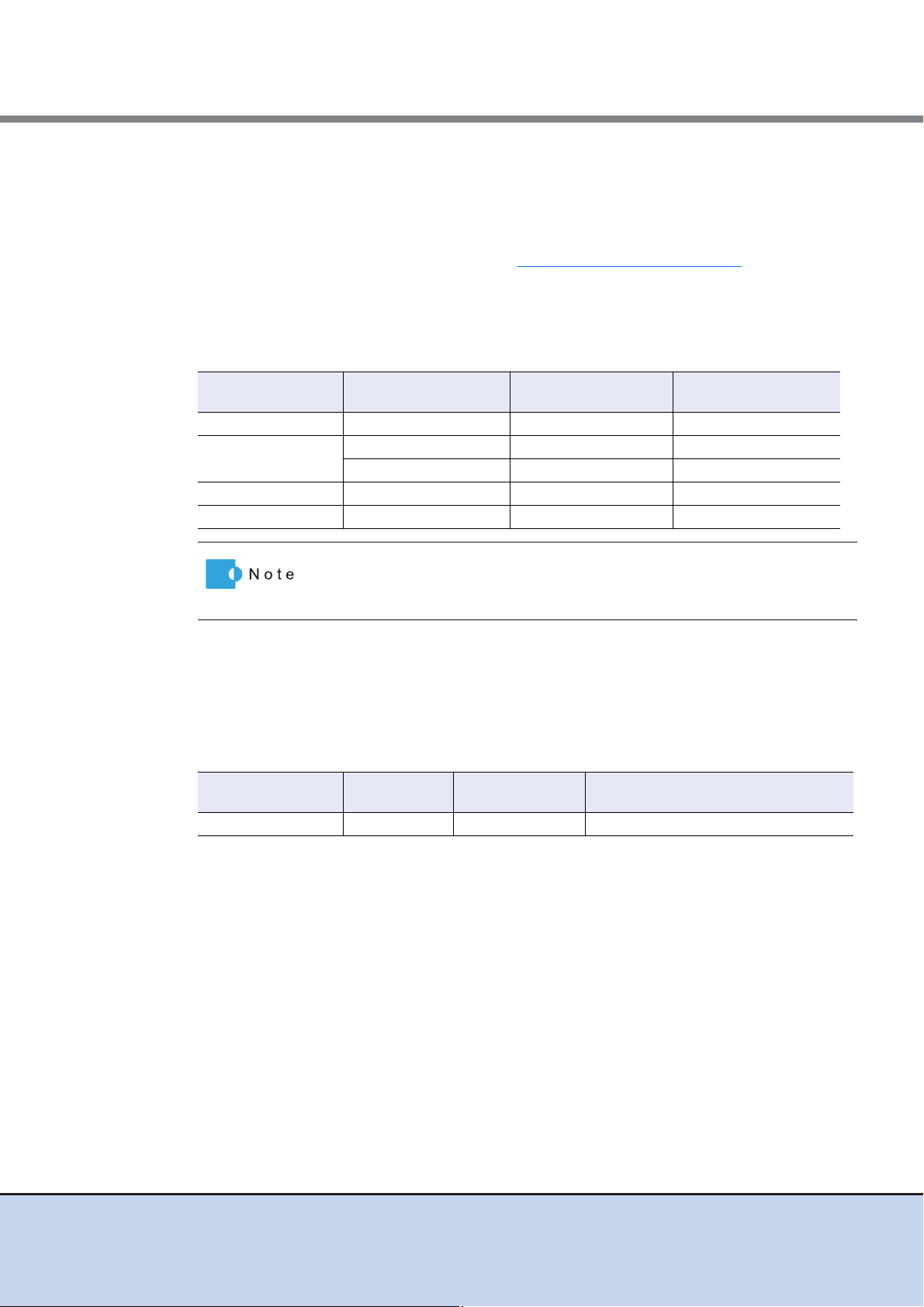
Table 1.1 Host interface adapter specifications......................................................................................... 16
Table 1.2 Drive interface port specifications.............................................................................................. 16
Table 1.3 LAN port specifications .............................................................................................................. 17
Table 1.4 Drive interface port specifications.............................................................................................. 21
Table 1.5 2.5" drive specifications ............................................................................................................. 24
Table 1.6 3.5" drive specifications ............................................................................................................. 24
Table 1.7 Power distribution unit (AC200-240V, 1U, Max 2 enclosures connection) and
provided AC cable specifications............................................................................................... 25
Table 1.8 Power distribution unit (AC200-240V, 2U, Max 6 enclosures connection) and
provided AC cable specifications............................................................................................... 26
Table 1.9 Power distribution unit (AC200-240V, 2U, Max 8 enclosures connection) and
provided AC cable specifications............................................................................................... 27
Table 2.1 ETERNUS DX80 S2 installation specifications ......................................................................... 28
Table 2.2 ETERNUS DX90 S2 installation specifications ......................................................................... 30
Table 2.3 Package size (for regions other than EMEA&I) ......................................................................... 32
Table 2.4 Specifications for power cords supplied with the ETERNUS DX Disk storage system
(for the EMEA&I region) ............................................................................................................ 35
Table 2.5 Specifications for power cords supplied with the ETERNUS DX Disk storage system
(for regions other than EMEA&I) ............................................................................................... 36
Table 2.6 Specifications for power distribution unit for DX80 S2/DX90 S2 (AC200-240V, 1U,
Max 2 enclosures connection)................................................................................................... 36
Table 2.7 Specifications for power distribution unit for DX80 S2/DX90 S2 (AC200-240V, 2U,
Max 6 enclosures connection)................................................................................................... 36
Table 2.8 Specifications for power distribution unit for DX80 S2/DX90 S2 (AC200-240V, 2U,
Max 8 enclosures connection)................................................................................................... 37
Table 2.9 Required number of outlets and sockets to install power distribution units ............................... 37
Table 2.10 Required conditions for distribution board circuit protectors...................................................... 39
Table 3.1 Ethernet frame capacity (Jumbo Frame settings)...................................................................... 45
Table 3.2 Connectable models and available remote interfaces ............................................................... 51
Table 3.3 ETERNUS Web GUI operating environment ............................................................................. 52
Table 4.1 Enclosure installation order ....................................................................................................... 57
Table 4.2 Specifications for the unit installation area ................................................................................ 62
Table 4.3 Recommended number of hot spares for each drive type......................................................... 62
Table 4.4 Priority order of host interface adapter installation .................................................................... 63
Table 4.5 Priority order of drive enclosure installation (for 2.5" type controller enclosure)........................ 64
Table 4.6 Priority order of drive enclosure installation (for 3.5" type controller enclosure)........................ 64
Table 4.7 Priority order of 2.5" drive installation ........................................................................................ 65
Table 4.8 Priority order of 3.5" drive installation ........................................................................................ 66
10
ETERNUS DX80 S2/DX90 S2 Disk storage system User’s Guide -Site Planning-
Copyright 2011 FUJITSU LIMITED P3AM-4822-03ENZ0
Chapter 1 Hardware Configurations
IMPORTANT
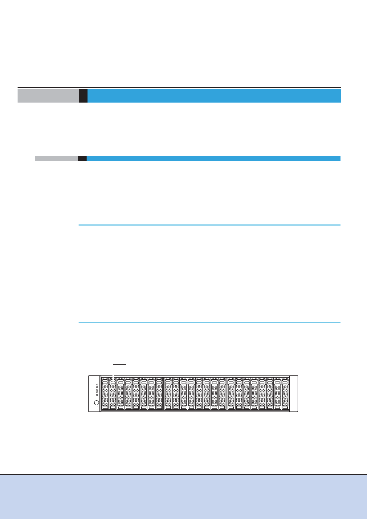
2.5" disk or 2.5" Solid State Drive (SSD)
This chapter explains hardware configurations for the ETERNUS DX Disk storage system.
1.1 Controller Enclosure
This section explains the main components in the controller enclosure.
The controller enclosure contains drives installed in the front, and controllers and power supply
units in the rear.
Since the power supply units are redundant, operations can continue even if one of them fails.
There are two models: a single-controller type and a dual-controller type. For a dual-controller
type, operations can continue even if one of the controllers fails.
• The single-controller type differs from the dual-controller type by the fol-
lowing features:
- The controller and I/O module are not duplicated.
- Hot maintenance or swapping of the controller and I/O module is not
possible.
- Concurrent firmware loading or update of the controller firmware and
I/O module firmware is not possible.
- Multipath connection to a single server is not available.
• Fujitsu recommends that the dual-controller types, in which the controller
and I/O module are duplicated, be used in a system where a high level of
reliability is required.
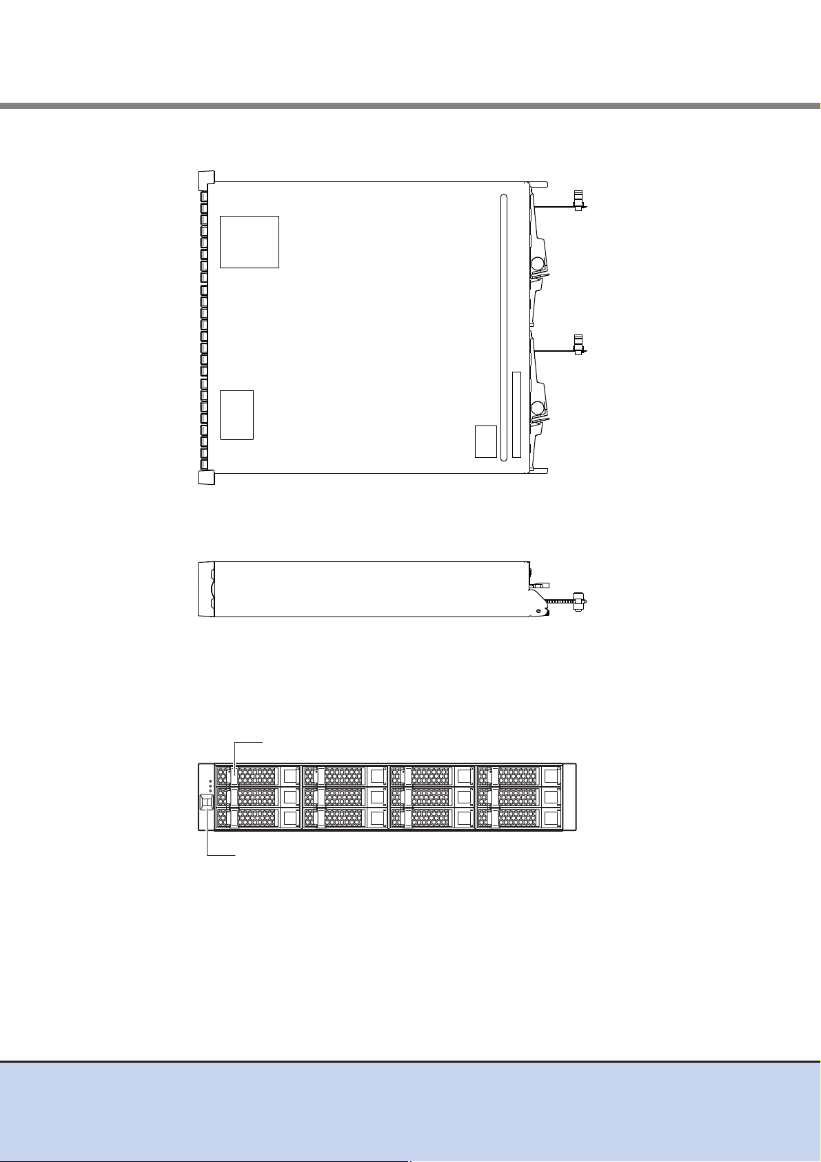
■ External views of a 2.5" type controller enclosure
● Front view
Figure 1.1 Front view of a 2.5" type controller enclosure
11
ETERNUS DX80 S2/DX90 S2 Disk storage system User’s Guide -Site Planning-
Copyright 2011 FUJITSU LIMITED P3AM-4822-03ENZ0

Chapter 1 Hardware Configurations
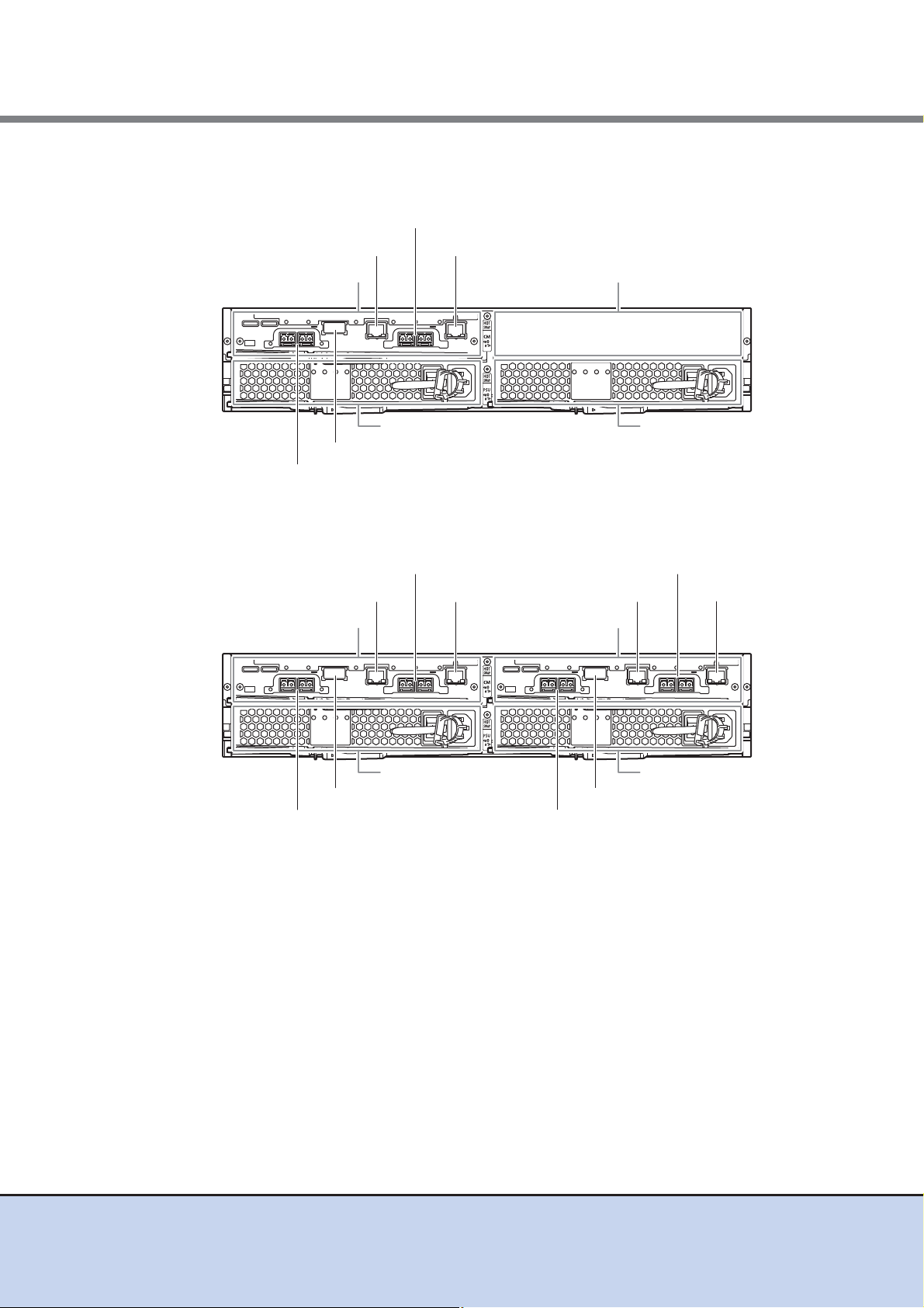
Power supply unit (PSU#1)Power supply unit (PSU#0)
Controller (CM#0)
LAN (MNT) portLAN (RMT) port
Drive interface (OUT) port
Host interface adapter (CA#0)
Host interface adapter (CA#1)
Cover
Power supply unit (PSU#1)
Controller (CM#1)
LAN (RMT) port
Drive interface (OUT) port
Host interface adapter (CA#0)
Power supply unit (PSU#0)
Controller (CM#0)
LAN (MNT) portLAN (RMT) port
Drive interface (OUT) port
Host interface adapter (CA#0)
LAN (MNT) port
Host interface adapter (CA#1) Host interface adapter (CA#1)
1.1 Controller Enclosure
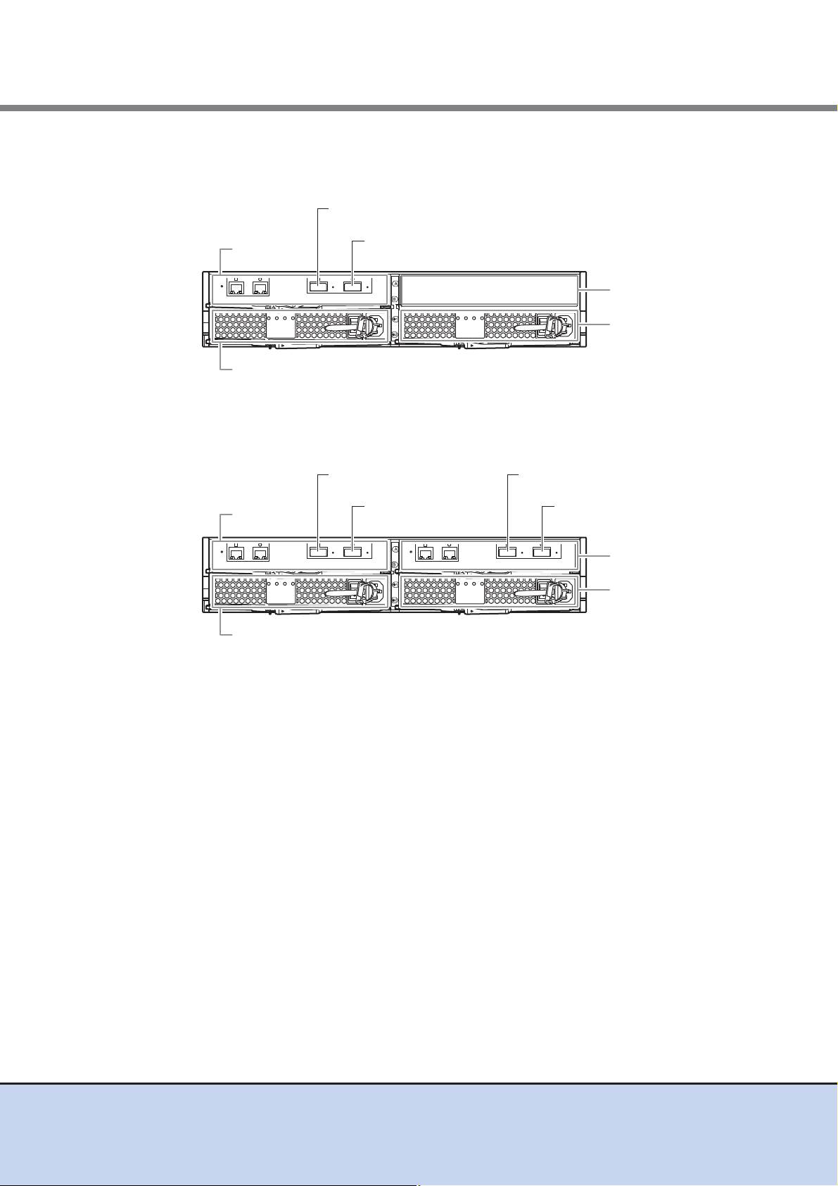
● Rear view
• Single-controller type
Figure 1.2 Rear view of a 2.5" type controller enclosure (single-controller type)
• Dual-controller type
Figure 1.3 Rear view of a 2.5" type controller enclosure (dual-controller type)
12
ETERNUS DX80 S2/DX90 S2 Disk storage system User’s Guide -Site Planning-
Copyright 2011 FUJITSU LIMITED P3AM-4822-03ENZ0
Chapter 1 Hardware Configurations
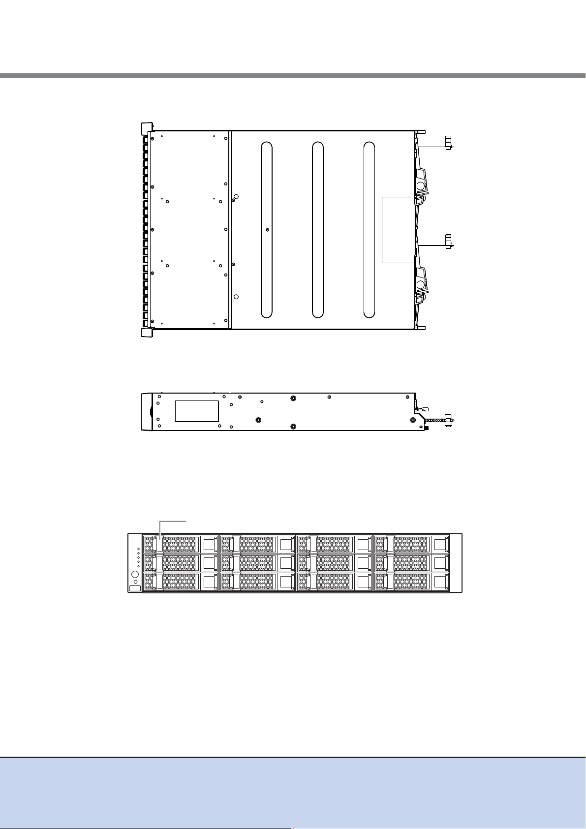
3.5" disk or 3.5" Solid State Drive (SSD)
1.1 Controller Enclosure
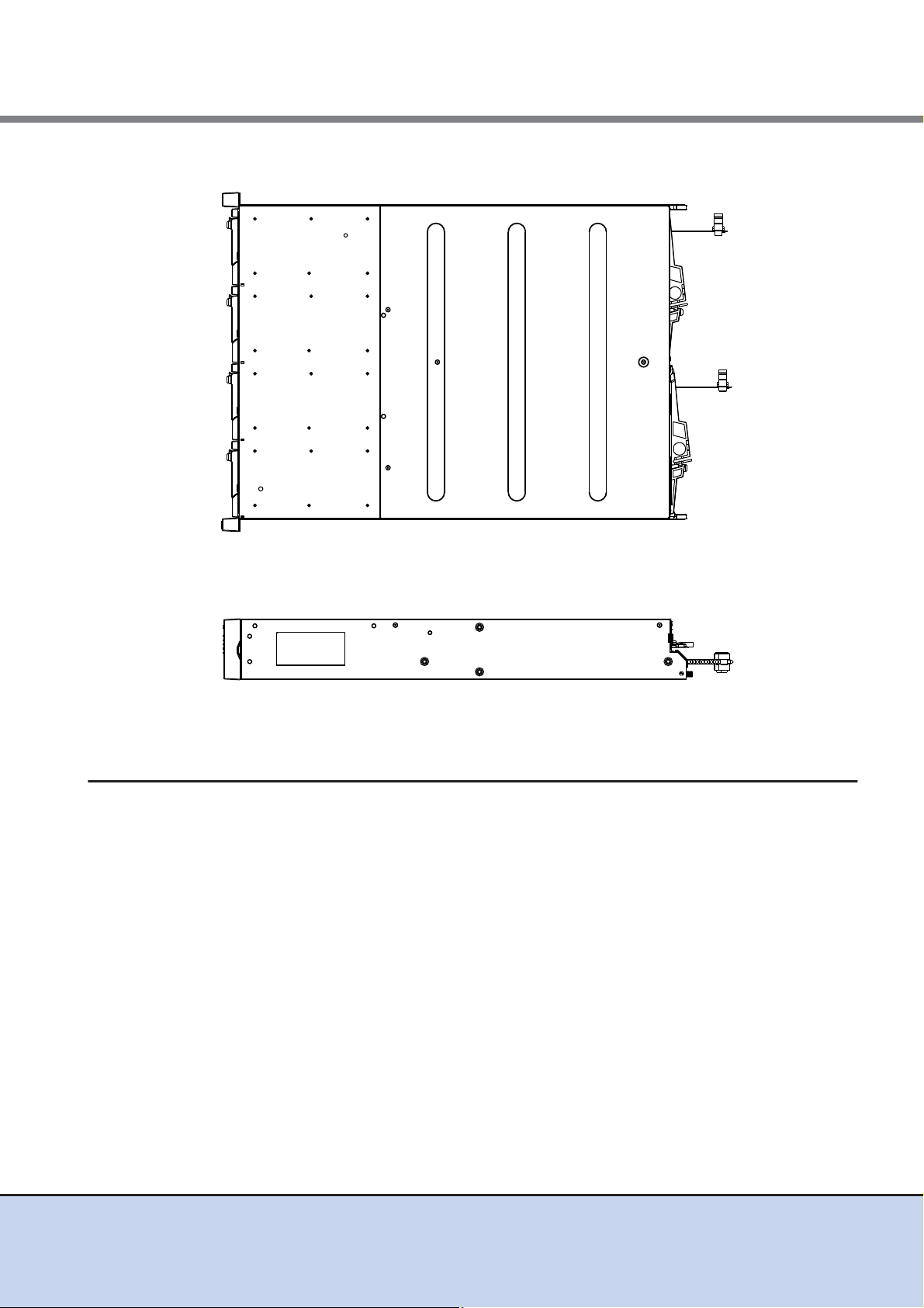
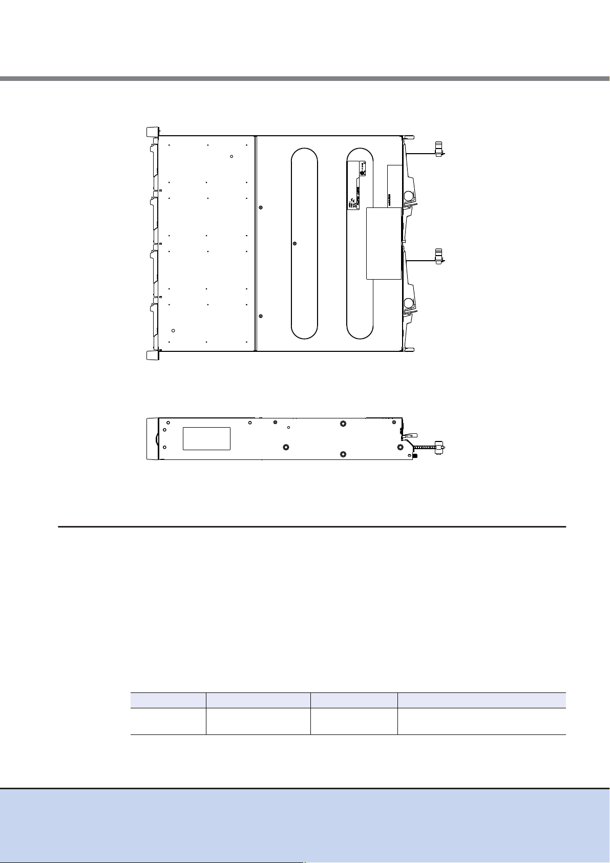
● Top view
Figure 1.4 Top view of a 2.5" type controller enclosure
● Side view
Figure 1.5 Side view of a 2.5" type controller enclosure
■ External views of a 3.5" type controller enclosure
● Front view
Figure 1.6 Front view of a 3.5" type controller enclosure
ETERNUS DX80 S2/DX90 S2 Disk storage system User’s Guide -Site Planning-
13
Copyright 2011 FUJITSU LIMITED P3AM-4822-03ENZ0
Chapter 1 Hardware Configurations
Power supply unit (PSU#1)Power supply unit (PSU#0)
Controller (CM#0)
LAN (MNT) portLAN (RMT) port
Drive interface (OUT) port
Host interface adapter (CA#0)
Host interface adapter (CA#1)
Cover
Power supply unit (PSU#1)
Controller (CM#1)
LAN (RMT) port
Drive interface (OUT) port
Host interface adapter (CA#0)
Power supply unit (PSU#0)
Controller (CM#0)
LAN (MNT) portLAN (RMT) port
Drive interface (OUT) port
Host interface adapter (CA#0)
LAN (MNT) port
Host interface adapter (CA#1) Host interface adapter (CA#1)
1.1 Controller Enclosure
● Rear view
• Single-controller type
Figure 1.7 Rear view of a 3.5" type controller enclosure (single-controller type)
• Dual-controller type
Figure 1.8 Rear view of a 3.5" type controller enclosure (dual-controller type)
14
ETERNUS DX80 S2/DX90 S2 Disk storage system User’s Guide -Site Planning-
Copyright 2011 FUJITSU LIMITED P3AM-4822-03ENZ0
Chapter 1 Hardware Configurations
1.1 Controller Enclosure
● Top view
Figure 1.9 Top view of a 3.5" type controller enclosure
● Side view
Figure 1.10 Side view of a 3.5" type controller enclosure
1.1.1 Controllers
The controller contains a CPU, cache memory, System Capacitor Unit (SCU), non-volatile memory, host interface adapters, drive interface ports, and LAN ports. The controller controls all operations in the ETERNUS DX Disk storage system.
■ CPU
A single core processor is installed.
■ Cache memory
Cache memory enables high speed processing by storing frequently used data.
The cache memory capacity for each controller is 2GB for the ETERNUS DX80 S2 and 4GB for
the ETERNUS DX90 S2.
15
ETERNUS DX80 S2/DX90 S2 Disk storage system User’s Guide -Site Planning-
Copyright 2011 FUJITSU LIMITED P3AM-4822-03ENZ0
Chapter 1 Hardware Configurations
1.1 Controller Enclosure
■ Host interface adapters
The host interface adapter has interface ports to connect a controller to a server.
Up to two host interface adapters can be installed in the controller of an ETERNUS DX Disk storage system. Different types of host interface adapters can exist together in the same controller.
For details about the installation rules, refer to "4.4.1 Host Interfaces" (page 63)
FC, iSCSI, FCoE, and SAS are available as host interface.
The following table shows the host interface adapter specifications.
Table 1.1 Host interface adapter specifications
.
Interface Transfer speed (max.) Connector type
FC 8Gbit/s SFP+ 2
iSCSI
FCoE 10Gbit/s SFP+ 2
SAS 6Gbit/s miniSAS (SFF-8088) 2
10Gbit/s SFP+ 2
1Gbit/s RJ-45 2
To perform remote copy using an FC or an iSCSI interface, change the port
mode settings from the host interface (CA) to the remote interface (RA) via
ETERNUS Web GUI or ETERNUS CLI.
■ Drive interface ports
A drive interface port is used to connect drive enclosures.
The following table shows the drive interface port specifications.
Table 1.2 Drive interface port specifications
Interface
SAS 6Gbit/s QSFP 1
Transfer
speed (max.)
Connector type Number of ports for each controller
Number of ports for
each adapter
■ LAN ports
Two LAN ports (RJ-45) are installed in each controller.
● Regions other than EMEA&I
Each LAN port is used for operation management (MNT port) and for remote support function
(RMT port) respectively.
● EMEA&I region
The MNT port is used for operation management and the RMT port is used for maintenance.
16
ETERNUS DX80 S2/DX90 S2 Disk storage system User’s Guide -Site Planning-
Copyright 2011 FUJITSU LIMITED P3AM-4822-03ENZ0

Chapter 1 Hardware Configurations
1.2 Drive Enclosures
The following table shows the LAN port specifications.
Table 1.3 LAN port specifications
Interface
Ethernet
(1000Base-T/100Base-TX/10Base-T)
■ SCU
A System Capacitor Unit (SCU) is installed in a controller as a backup power source in case of
power outage.
The SCU is charged from an external power source while the ETERNUS DX Disk storage system is running normally. If a power failure is detected, data in the cache memory is saved to the
non-volatile memory in the controller using the SCU. There is no limit to the post-failure data
retention time.
1.1.2 Power Supply Units
The power supply unit transforms input AC power from a power socket to DC power and supplies
power to each component. Two power supply units are installed in each controller enclosure.
Each power supply unit contains fans.
Transfer
speed (max.)
1Gbit/s RJ-45 2
Connector type
Number of ports
for each controller
1.2 Drive Enclosures
This section explains the main components in the drive enclosure.
The drive enclosure contains drives installed in the front, and I/O modules and power supply
units in the rear. Up to 24 drives can be installed in a 2.5" type drive enclosure. Up to 12 drives
can be installed in a 3.5" type drive enclosure.
Since the power supply units are redundant, operations can continue even if one of them fails.
When a drive enclosure is connected, a DE-ID (drive enclosure number) is automatically allocated.
17
ETERNUS DX80 S2/DX90 S2 Disk storage system User’s Guide -Site Planning-
Copyright 2011 FUJITSU LIMITED P3AM-4822-03ENZ0
Chapter 1 Hardware Configurations
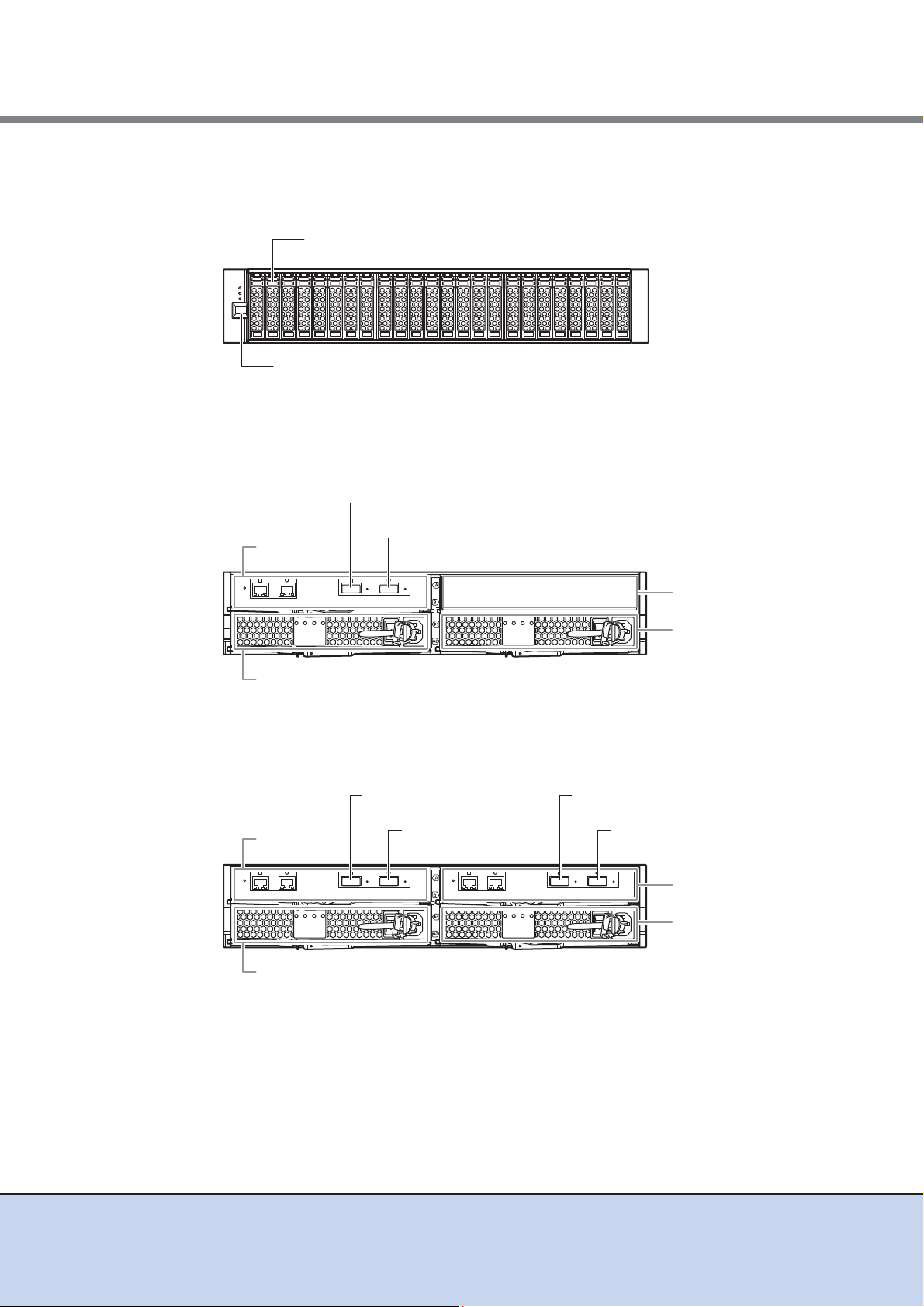
2.5" disk or 2.5" Solid State Drive (SSD)
DE-ID display panel
Power supply
unit (PSU#1)
Cover
Drive interface (IN) port
Power supply
unit (PSU#0)
I/O module
(IOM6#0)
Drive interface (OUT) port
Power supply
unit (PSU#1)
I/O module
(IOM6#1)
Drive interface (IN) port
Drive interface (IN) port
Drive interface (OUT) port
Power supply
unit (PSU#0)
I/O module
(IOM6#0)
Drive interface (OUT) port
1.2 Drive Enclosures
■ 2.5" type drive enclosure
● Front view
Figure 1.11 Front view of a 2.5" type drive enclosure
● Rear view
• Single-IOM type
Figure 1.12 Rear view of a drive enclosure (single-IOM type)
• Dual-IOM type
Figure 1.13 Rear view of a drive enclosure (dual-IOM type)
ETERNUS DX80 S2/DX90 S2 Disk storage system User’s Guide -Site Planning-
18
Copyright 2011 FUJITSU LIMITED P3AM-4822-03ENZ0
Chapter 1 Hardware Configurations
3.5" disk or 3.5" Solid State Drive (SSD)
DE-ID display panel
1.2 Drive Enclosures
● Top view
Figure 1.14 Top view of a 2.5" type drive enclosure
● Side view
Figure 1.15 Side view of a 2.5" type drive enclosure
■ 3.5" type drive enclosure
● Front view
Figure 1.16 Front view of a 3.5" type drive enclosure
ETERNUS DX80 S2/DX90 S2 Disk storage system User’s Guide -Site Planning-
19
Copyright 2011 FUJITSU LIMITED P3AM-4822-03ENZ0
Chapter 1 Hardware Configurations
Power supply
unit (PSU#1)
Cover
Drive interface (IN) port
Power supply
unit (PSU#0)
I/O module
(IOM6#0)
Drive interface (OUT) port
Power supply
unit (PSU#1)
I/O module
(IOM6#1)
Drive interface (IN) port
Drive interface (IN) port
Drive interface (OUT) port
Power supply
unit (PSU#0)
I/O module
(IOM6#0)
Drive interface (OUT) port
1.2 Drive Enclosures
● Rear view
• Single-IOM type
Figure 1.17 Rear view of a drive enclosure (single-IOM type)
• Dual-IOM type
Figure 1.18 Rear view of a drive enclosure (dual-IOM type)
ETERNUS DX80 S2/DX90 S2 Disk storage system User’s Guide -Site Planning-
20
Copyright 2011 FUJITSU LIMITED P3AM-4822-03ENZ0
Chapter 1 Hardware Configurations
1.2 Drive Enclosures
● Top view
Figure 1.19 Top view of a 3.5" type drive enclosure
● Side view
Figure 1.20 Side view of a 3.5" type drive enclosure
1.2.1 I/O Modules
The I/O module is a component that controls the interaction between the controller and the
drives.
The I/O module is connected to the controller or an I/O module on another drive enclosure.
■ Drive interface ports
A drive interface port is used to connect a controller enclosure or drive enclosures.
The drive interface port has an IN port and an OUT port.
The following table shows the drive interface port specifications.
Table 1.4 Drive interface port specifications
Interface Transfer speed (max.) Connector type Number of ports for each I/O module
SAS 6Gbit/s QSFP
1 (IN)
1 (OUT)
21
ETERNUS DX80 S2/DX90 S2 Disk storage system User’s Guide -Site Planning-
Copyright 2011 FUJITSU LIMITED P3AM-4822-03ENZ0
Chapter 1 Hardware Configurations
DIDI
DE #02
DIDI
DE #01
DIDI
DE #09
DE #0x
DIDI
CE
DI: Drive interface port
DIDI
DIDI
1.3 Enclosure Connection Path
1.2.2 Power Supply Units
The power supply unit transforms input AC power from a power socket to DC power and supplies
power to each component. Two power supply units are installed in each drive enclosure.
Each power supply unit contains fans.
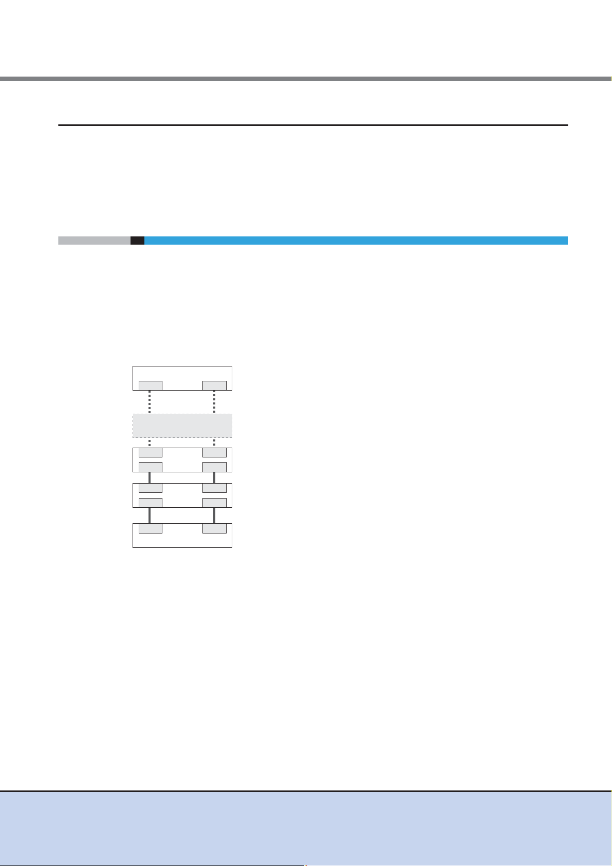
1.3 Enclosure Connection Path
For a dual-controller type, a controller enclosure (CE) is connected to drive enclosures (DE) with
multiple paths.
A drive enclosure has two independent drive interface ports. Path redundancy is maintained by
connecting the drive enclosure to two controllers directly. This configuration allows operation to
continue even if one of the connection paths fails.
Up to nine drive enclosures can be connected to a controller enclosure as shown in the figures
below.
Figure 1.21 Enclosure connection path (dual-controller type)
22
ETERNUS DX80 S2/DX90 S2 Disk storage system User’s Guide -Site Planning-
Copyright 2011 FUJITSU LIMITED P3AM-4822-03ENZ0
 Loading...