

Eternus DX60, DX80, DX90 User Manual


ETERNUS DX60/DX80/DX90 Disk storage system User Guide
3
Copyright 2010 FUJITSU LIMITED
P3AM-3042-07ENZ0
Preface
Fujitsu would like to thank you for purchasing our ETERNUS DX60/DX80/DX90 Disk storage
system.
The ETERNUS DX60/DX80/DX90 Disk storage system is designed to be connected to a Fujitsu
(PRIMEQUEST, PRIMERGY, or SPARC Enterprise) or other server.
This guide introduces the user to the ETERNUS DX60/DX80/DX90 Disk storage system
(referred to as just "ETERNUS DX60/DX80/DX90" in the remainder of this manual), and explains
the regular checks and maintenance required.
This guide is intended for use of ETERNUS DX60/DX80/DX90 in regions other than Japan and
EMEA (Europe, Middle East and Africa).
Please carefully review the information outlined in this manual.
Seventh Edition
July 2010
Applicable Environment
The ETERNUS DX60/DX80/DX90 was designed and manufactured with user safety in mind.
When using the ETERNUS DX60/DX80/DX90, follow the handling instructions, placement and
cautionary notes listed in this guide. If used beyond the limits described, the users may be at risk
of personal injury and/or material damage.
Using this Manual
The manuals provided with the ETERNUS DX60/DX80/DX90 contain important information
regarding safe usage.
Please read these manuals carefully before using the ETERNUS DX60/DX80/DX90. Pay special
attention to "ETERNUS DX60/DX80/DX90 Disk storage system Safety Precautions", and understand the contents thoroughly before connecting. Keep these manuals in a safe place for future
reference.
Fujitsu pays careful attention to the safe use of its products to prevent user injury and/or material
damage. To use the ETERNUS DX60/DX80/DX90 properly, please follow the instructions in this
manual.
Preface
ETERNUS DX60/DX80/DX90 Disk storage system User Guide
4
Copyright 2010 FUJITSU LIMITED
P3AM-3042-07ENZ0
UNIX is a registered trademark of The Open Group in the United States and other countries.
Microsoft, Windows, Windows Server, SQL Server, and Exchange Server are either registered
trademarks or trademarks of Microsoft Corporation in the United States and/or other countries.
Sun, Sun Microsystems, the Sun Logo, Solaris and all Solaris based marks and logos are trademarks or registered trademarks of Sun Microsystems, Inc. in the U.S. and other countries, and
are used under license.
All SPARC marks are trademarks or registered trademarks of SPARC International, Inc. in the
U.S. and other countries, and are used under license. Products with a SPARC mark are based
on the architecture developed by Sun Microsystems, Inc.
HP-UX is a trademark of Hewlett-Packard in the U.S. and other countries.
Linux is a trademark or registered trademark of Linus Torvalds in the U.S. and other countries.
AIX is a trademark of IBM Corp.
VMware, VMware logos, Virtual SMP, and VMotion are either registered trademarks or trademarks of VMware, Inc. in the U.S. and/or other countries.
Oracle is a registered trademark of Oracle Corporation and/or its affiliates.
The company names, product names and service names mentioned in this document are registered trademarks or trademarks of their respective companies.
Screen shot(s) reprinted with permission from Microsoft Corporation.
Copyright 2010 FUJITSU LIMITED
The ETERNUS DX60/DX80/DX90 is designed, developed and manufactured as contemplated
for general use, including without limitation, general office use, personal use, household use,
and ordinary industrial use, but is not designed, developed and manufactured for use in
situations with accompanying fatal risks or dangers that, unless extremely high safety is
secured, could lead directly to death, personal injury, severe physical damage or other loss
(hereinafter "High Safety Required Use"), including without limitation, nuclear reaction control
in nuclear facility, aircraft flight control, air traffic control, mass transport control, medical life
support system, and missile launch control in weapon systems. Do not use the ETERNUS
DX60/DX80/DX90 for High Safety Required Use without securing the sufficient safety level
required. If you wish to use the ETERNUS DX60/DX80/DX90 for High Safety Required Use,
please consult with our sales representative before such use.
Electromagnetic compatibility
Emissions: FCC Class A, EN55022 Class A and CNS 13438 Class A
Immunity: EN55024
Safety
CAN/CSA C22.2 No. 60950, UL60950 and EN60950
Class 1 laser product

Preface
ETERNUS DX60/DX80/DX90 Disk storage system User Guide
5
Copyright 2010 FUJITSU LIMITED
P3AM-3042-07ENZ0

ETERNUS DX60/DX80/DX90 Disk storage system User Guide
6
Copyright 2010 FUJITSU LIMITED
P3AM-3042-07ENZ0
About this Manual
Organization
This manual is organized as follows:
• Chapter 1 Overview
This chapter describes the special features, data configurations of RAID groups, and
specifications of the ETERNUS DX60/DX80/DX90.
• Chapter 2 Components
This chapter describes the components of the ETERNUS DX60/DX80/DX90.
• Chapter 3 Standard Operations
This chapter describes how to turn the ETERNUS DX60/DX80/DX90 on and off, and how to
attach and remove the front cover or flange cover.
• Chapter 4 Flow from Installation to Operation
This chapter describes the flow of work from installation to the start of ETERNUS DX60/
DX80/DX90 operation.
• Chapter 5 Installation
This chapter describes the ETERNUS DX60/DX80/DX90 installation.
• Chapter 6 Cable Connection
This chapter describes how to connect various cables to the ETERNUS DX60/DX80/DX90.
• Chapter 7 Setup
This chapter describes how to set up the ETERNUS DX60/DX80/DX90 for operation.
• Chapter 8 Installing Optional Products
This chapter describes how to install optional products.
• Chapter 9 Operation and Maintenance
This chapter describes points to note when operating and performing maintenance for the
ETERNUS DX60/DX80/DX90. It also describes how to change the configuration and the
appropriate response to any problems which may occur.
Read this chapter when operating or performing maintenance on the ETERNUS DX60/DX80/
DX90, or if an error occurs.
"Specifications", "Events detected by ServerView", and "About Using of Open Sources" are
described as appendixes.
Refer to the manuals for each peripheral concerning details not included in this manual.
About this Manual
ETERNUS DX60/DX80/DX90 Disk storage system User Guide
7
Copyright 2010 FUJITSU LIMITED
P3AM-3042-07ENZ0
Warning Notations
Warning signs are shown throughout this manual in order to prevent injury to the user and/or
material damage. These signs are composed of a symbol and a message describing the recommended level of caution. The following explains the symbols, their levels of caution, and their
meanings as used in this manual.
The following symbols are used to indicate the type of warnings or cautions being described.
WARNING
This symbol indicates the possibility of serious or fatal injury if the
ETERNUS DX60/DX80/DX90 is not used properly.
CAUTION
This symbol indicates the possibility of minor or moderate personal
injury, as well as damage to the ETERNUS DX60/DX80/DX90 and/or to
other users and their property, if the ETERNUS DX60/DX80/DX90 is not
used properly.
I
MPORTAN
T
This symbol indicates IMPORTANT information for the user to note
when using the ETERNUS DX60/DX80/DX90.
E
lectric Shoc
k
The triangle emphasizes the urgency of the WARNING and
CAUTION contents. Inside the triangle and above it are details
concerning the symbol (e.g. Electrical Shock).
N
o Disassemb
ly
The barred "Do Not..." circle warns against certain actions. The
action which should be avoided is both illustrated inside the barred circle
and written above it (e.g. No Disassembly).
Unplu
g
The black "Must Do..." disk indicates actions that must be taken.
The required action is both illustrated inside the black disk and written
above it (e.g. Unplug).

About this Manual
ETERNUS DX60/DX80/DX90 Disk storage system User Guide
8
Copyright 2010 FUJITSU LIMITED
P3AM-3042-07ENZ0
How Warnings are Presented in this Manual
A message is written beside the symbol indicating the caution level. This message is marked
with a vertical ribbon in the left margin, to distinguish this warning from ordinary descriptions.
An example is shown here.
Additional Information
Expressions and abbreviations
The following are expressions and abbreviations used throughout this manual:
Product names and abbreviations
• "Windows®" represents the following products.
- Microsoft® Windows® 2000 operating system
- Microsoft® Windows Server® 2003 operating system
- Microsoft® Windows Server® 2008 operating system
Warning Level Indicator
Warning T ype Indicator
Warning Details
To avoid damaging the ETERNUS DX60/DX80/DX90, pay attention to
the following points when cleaning the ETERNUS DX60/DX80/DX90:
- Make sure to disconnect the power when cleaning.
- Be careful that no liquid seeps into the ETERNUS DX60/DX80/DX90
when using cleaners, etc.
- Do not use alcohol or other solvents to clean the ETERNUS
DX60/DX80/DX90.
Warning Layout Ribbon
Example Warning
Functions and know how which can be useful when setting up or operating
the ETERNUS DX60/DX80/DX90.
Refer
This notation indicates related reference manuals.
About this Manual
ETERNUS DX60/DX80/DX90 Disk storage system User Guide
9
Copyright 2010 FUJITSU LIMITED
P3AM-3042-07ENZ0
Latest Information
The information in this document is subject to change without notice for functionality expansion
of ETERNUS DX60/DX80/DX90 and improvement. The latest version of this document and the
latest information about the ETERNUS DX60/DX80/DX90 is released in the following web-site.
Access the following address if needed.
http://www.fujitsu.com/global/services/computing/storage/eternus/products/diskstorage/dx-entry/
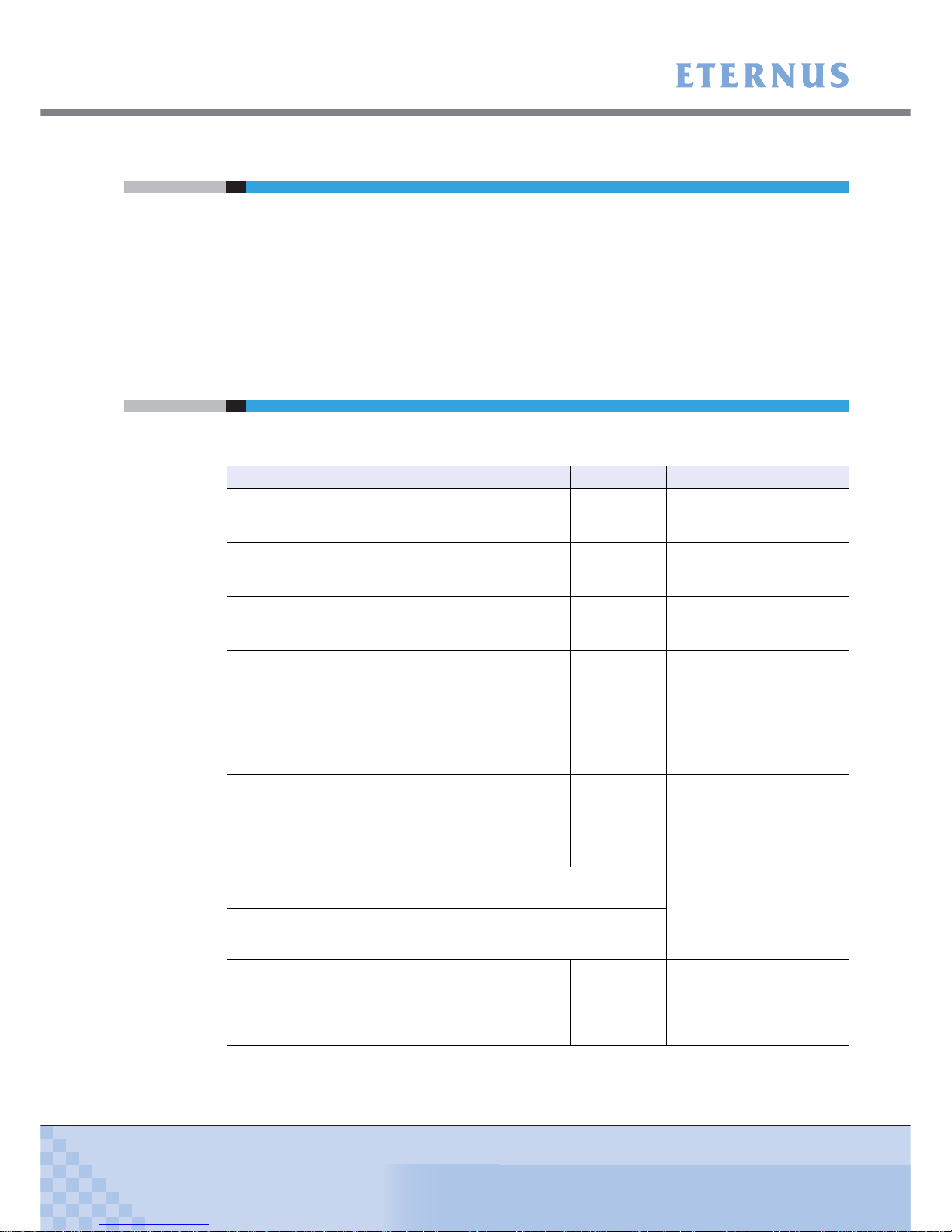
Related Manuals
Refer to the following related manuals in addition to this manual.
Manuals Code Description
ETERNUS DX60/DX80/DX90 Disk storage system
Setup Guide (Fibre Channel model)
P3AM-3082
This manual describes how
to ready Fibre Channel
model devices for operation.
ETERNUS DX60/DX80 Disk storage system Setup
Guide (iSCSI model)
P3AM-3092
This manual describes how
to ready iSCSI model
devices for operation.
ETERNUS DX60/DX80 Disk storage system Setup
Guide (SAS model)
P3AM-3102
This manual describes how
to ready SAS model devices
for operation.
ETERNUS DX60/DX80/DX90 Disk storage system
Safety Precautions
P3AM-3142
This manual describes the
points to note when
installing and operating the
device.
ETERNUS DX60/DX80/DX90 Disk storage system
Package Contents
P3AM-3062
This is the list of package
contents for the device and
optional products.
ETERNUS DX60/DX80/DX90 Disk storage system
Using Optional Products
P3AM-3152
This manual describes the
points to note when using
optional products.
ETERNUS DX60/DX80/DX90 Disk storage system
Feature activation licenses
P3AM-3312
This manual describes the
Advanced Copy license.
ETERNUS DX Disk storage systems Server Connection Guide
(Fibre Channel)
*1
This manual describes how
to connect the ETERNUS
DX60/DX80/DX90 to a
server.
ETERNUS DX Disk storage systems Server Connection Guide (iSCSI)
*1
ETERNUS DX Disk storage systems Server Connection Guide (SAS)
*1
ETERNUS DX60/DX80/DX90 Web GUI User Guide P2X0-0700
This manual describes how
to monitor and set the
ETERNUS DX60/DX80/
DX90 via Graphical User
Interface (GUI).

About this Manual
ETERNUS DX60/DX80/DX90 Disk storage system User Guide
10
Copyright 2010 FUJITSU LIMITED
P3AM-3042-07ENZ0
*1: Download the necessary manuals for the customer operating environment (for server OS, Fibre
Channel card type, etc.) from the specified web-site. For the URL of the download web-site, refer to
the Documentation CD provided with the ETERNUS DX60/DX80/DX90.
ETERNUS DX60/DX80/DX90 CLI User Guide P2X0-0710
This manual describes how
to monitor and set the
ETERNUS DX60/DX80/
DX90 via Command Line
Interface (CLI).
ETERNUS Multipath Driver V2.0 User's Guide
This manual describes how
to use the optional
ETERNUS Multipath Driver.
(For Windows®) P2WW-1451
(For Linux) P2U3-0031
(For AIX) P2U3-0051
ETERNUS Multipath Driver V3.0 User's Guide
For Solaris™ Operating System P2S0-0062
ETERNUS MPIO for IBM AIX V2.0.2
Installation & Configuration Guide for AIX
P2U3-0150
Manuals Code Description

ETERNUS DX60/DX80/DX90 Disk storage system User Guide
11
Copyright 2010 FUJITSU LIMITED
P3AM-3042-07ENZ0
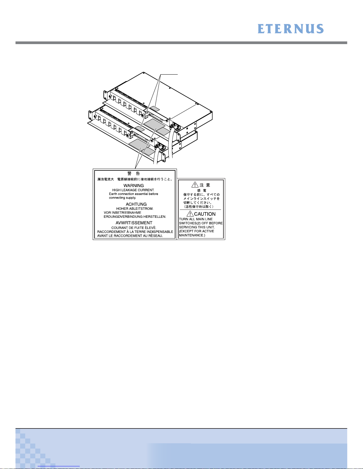
Labels
Warning labels and manufacturer's labels are found in various places of the ETERNUS DX60/
DX80/DX90, as shown in the example below.
Do not remove these labels.
■ Controller Enclosure
Manufacturer’s label
The label with the model, serial #, etc.
is located here.

Labels
ETERNUS DX60/DX80/DX90 Disk storage system User Guide
12
Copyright 2010 FUJITSU LIMITED
P3AM-3042-07ENZ0
■ Drive Enclosure
■ AC Outlet Box (1U)
Manufacturer’s label
The label with the model, serial #, etc.
is located here.
Labels
ETERNUS DX60/DX80/DX90 Disk storage system User Guide
13
Copyright 2010 FUJITSU LIMITED
P3AM-3042-07ENZ0
■ AC Outlet Box (2U)
Manufacturer’s label
The label with the model, serial #, etc.
is located here.

ETERNUS DX60/DX80/DX90 Disk storage system User Guide
14
Copyright 2010 FUJITSU LIMITED
P3AM-3042-07ENZ0
Contents
Chapter 1 Overview .................................................................................22
1.1 System Features .............................................................................................. 22
1.2 Configuration .................................................................................................... 26
1.2.1 RAID Level ................................................................................................................................ 26
1.2.2 RAID Groups and Volumes ....................................................................................................... 32
1.2.3 System Disks ............................................................................................................................. 33
1.2.4 Hot Spare .................................................................................................................................. 34
1.2.5 Disks .......................................................................................................................................... 35
1.2.6 Host Interface ............................................................................................................................ 35
1.3 Functions .......................................................................................................... 36
1.3.1 Rebuild/Copyback ..................................................................................................................... 36
1.3.2 Redundant Copy ........................................................................................................................ 38
1.3.3 Advanced Copy ......................................................................................................................... 39
1.3.4 RAID Migration .......................................................................................................................... 42
1.3.5 Logical Device Expansion ......................................................................................................... 44
1.3.6 LUN Concatenation ................................................................................................................... 45
1.3.7 Security Functions ..................................................................................................................... 46
1.3.8 Eco-mode .................................................................................................................................. 48
Chapter 2 Components ...........................................................................49
2.1 3.5" Type Controller Enclosure ........................................................................ 49
2.1.1 Front View ................................................................................................................................. 49
2.1.2 Rear View .................................................................................................................................. 51
2.2 2.5" Type Controller Enclosure ........................................................................ 57
2.2.1 Front View ................................................................................................................................. 57
2.2.2 Rear View .................................................................................................................................. 59
2.3 3.5" Type Drive Enclosure ................................................................................ 63
2.3.1 Front View ................................................................................................................................. 63
2.3.2 Rear View .................................................................................................................................. 65
2.4 2.5" Type Drive Enclosure ................................................................................ 67
2.4.1 Front View ................................................................................................................................. 67
2.4.2 Rear View .................................................................................................................................. 69
2.5 AC Outlet Box .................................................................................................. 71
2.5.1 AC Outlet Box (1U) .................................................................................................................... 71
2.5.2 AC Outlet Box (2U) .................................................................................................................... 71
Chapter 3 Standard Operations..............................................................72
3.1 Power ON Control ............................................................................................ 72
3.2 Power OFF Control .......................................................................................... 74

Contents
ETERNUS DX60/DX80/DX90 Disk storage system User Guide
15
Copyright 2010 FUJITSU LIMITED
P3AM-3042-07ENZ0
3.3 Attaching and Removing the Front Cover ........................................................ 75
3.4 Attaching and Removing the Flange Cover ..................................................... 78
3.5 Turning the AUTO POWER Switch On/Off ...................................................... 79
3.6 Wearing the Wrist Strap ................................................................................... 81
Chapter 4 Flow from Installation to Operation......................................82
Chapter 5 Installation ..............................................................................86
5.1 Installation Preparation .................................................................................... 86
5.1.1 Placement Area ......................................................................................................................... 86
5.1.2 Check the Number of Wall Outlets ............................................................................................ 87
5.2 Rack Installation ............................................................................................... 88
5.2.1 Installing Controller Enclosure ................................................................................................... 91
5.2.2 Installing Drive Enclosure .......................................................................................................... 95
5.2.3 Installing AC Outlet Box (1U) ..................................................................................................... 99
5.2.4 Installing AC Outlet Box (2U) ................................................................................................... 102
Chapter 6 Cable Connection.................................................................106
6.1 Connection Preparation ................................................................................. 106
6.2 LAN Cable Connection (for Operation Management) .................................... 107
6.3 Fibre Channel Cable Connection (For Fibre Channel) ................................... 110
6.4 LAN Cable Connection (For iSCSI) ................................................................ 113
6.5 MiniSAS Cable Connection (For SAS) ........................................................... 115
6.6 MiniSAS Cable Connection (For Drive Enclosures) ....................................... 117
6.7 Power Cord Connection ................................................................................. 123
6.7.1 With No AC Outlet Box ............................................................................................................ 124
6.7.2 When 1U AC Outlet Box is Installed ........................................................................................126
6.7.3 When 2U AC Outlet Box is Installed ........................................................................................131
Chapter 7 Setup .....................................................................................136
7.1 Setup Preparation .......................................................................................... 136
7.2 Basic Setup .................................................................................................... 139
7.2.1 Initial Setup .............................................................................................................................. 140
7.2.2 Configuration Wizard ............................................................................................................... 149
7.2.3 Hot Spare Registration ............................................................................................................ 160
7.3 Advanced Copy Setup ................................................................................... 163
7.3.1 Obtaining the Advanced Copy License Key ............................................................................ 163
7.3.2 Registering the Advanced Copy License Key ......................................................................... 168
7.3.3 Advanced Copy Settings ......................................................................................................... 169
7.4 Monitoring Setup ............................................................................................ 169
7.4.1 Event Notification Setup .......................................................................................................... 169
7.4.2 E-mail Notification Setup ......................................................................................................... 172
7.4.3 ServerView (SNMP Trap Notification) Setup ........................................................................... 174

Contents
ETERNUS DX60/DX80/DX90 Disk storage system User Guide
16
Copyright 2010 FUJITSU LIMITED
P3AM-3042-07ENZ0
7.4.4 Remote Support Setup ............................................................................................................ 179
7.5 Server Connection Setup ............................................................................... 180
7.6 System Status Check ..................................................................................... 181
Chapter 8 Installing Optional Products ...............................................184
8.1 Disk Installation .............................................................................................. 184
8.1.1 Disk Handling Instructions ....................................................................................................... 184
8.1.2 Installable Disks ....................................................................................................................... 185
8.1.3 Disk Installation Positions ........................................................................................................ 186
8.1.4 Additional Disk Installation Procedure ..................................................................................... 186
8.2 Drive Enclosure Installation ............................................................................ 192
8.2.1 Drive Enclosure Handling Instructions .....................................................................................192
8.2.2 Installable Drive Enclosures .................................................................................................... 193
8.2.3 Drive Enclosure Rack Installation Procedure .......................................................................... 193
8.2.4 Additional Drive Enclosure Installation .................................................................................... 199
Chapter 9 Operation and Maintenance ................................................202
9.1 Checking the ETERNUS DX60/DX80/DX90 Status ....................................... 202
9.2 Backing up Data ............................................................................................. 202
9.3 Maintenance Service ...................................................................................... 203
9.3.1 Maintenance Support Period ................................................................................................... 203
9.4 Post Start-of-Operation Changes to the Configuration .................................. 203
9.4.1 Replacing Fibre Channel Cards .............................................................................................. 204
9.4.2 Replacing LAN Cards / iSCSI HBAs ........................................................................................ 205
9.4.3 Replacing SAS Cards .............................................................................................................. 206
9.5 Troubleshooting ............................................................................................. 207
9.5.1 Check List ................................................................................................................................ 207
9.5.2 Trouble Record ........................................................................................................................ 214
Appendix A Specifications .......................................................................216
A.1 Device Specifications ...................................................................................... 216
A.1.1 ETERNUS DX60 Specifications .............................................................................................. 216
A.1.2 ETERNUS DX80 Specifications .............................................................................................. 218
A.1.3 ETERNUS DX90 Specifications .............................................................................................. 220
A.2 Optional Product Specifications ...................................................................... 222
A.2.1 Disks ....................................................................................................................................... 222
A.2.2 Drive Enclosures ..................................................................................................................... 227
A.2.3 AC Outlet Box.......................................................................................................................... 228
A.2.4 Expansion Controller ............................................................................................................... 229
A.2.5 Expansion Expander ............................................................................................................... 229
A.2.6 Extension Cable Kit ................................................................................................................. 230

Contents
ETERNUS DX60/DX80/DX90 Disk storage system User Guide
17
Copyright 2010 FUJITSU LIMITED
P3AM-3042-07ENZ0
Appendix B Events detected by ServerView ..........................................231
Appendix C About Using of Open Sources ............................................232
Index .......................................................................................................235

ETERNUS DX60/DX80/DX90 Disk storage system User Guide
18
Copyright 2010 FUJITSU LIMITED
P3AM-3042-07ENZ0
Figure of Contents
Figure 1.1 RAID0 concept .......................................................................................................................... 27
Figure 1.2 RAID1 concept .......................................................................................................................... 27
Figure 1.3 RAID1+0 concept ...................................................................................................................... 28
Figure 1.4 RAID5 concept .......................................................................................................................... 28
Figure 1.5 RAID5+0 concept ...................................................................................................................... 29
Figure 1.6 RAID6 concept .......................................................................................................................... 30
Figure 1.7 Example of a RAID group.......................................................................................................... 32
Figure 1.8 RAID group concept .................................................................................................................. 32
Figure 1.9 Hot Spares................................................................................................................................. 34
Figure 1.10 Rebuild/Copyback function........................................................................................................ 36
Figure 1.11 Redundant Copy Function......................................................................................................... 38
Figure 1.12 Example of an Advanced Copy operation ................................................................................. 39
Figure 1.13 Example for use RAID Migration 1 ............................................................................................ 42
Figure 1.14 Example for use RAID Migration 2 ............................................................................................ 43
Figure 1.15 Example for use Logical Device Expansion .............................................................................. 44
Figure 1.16 Example for use LUN Concatenation ........................................................................................ 45
Figure 1.17 LUN Mapping function ............................................................................................................... 46
Figure 1.18 Host Affinity function.................................................................................................................. 47
Figure 1.19 Eco-mode mechanism............................................................................................................... 48
Figure 1.20 Setting example for Eco-mode schedule................................................................................... 48
Figure 2.1 Front view of 3.5" type controller enclosure (with front cover)................................................... 49
Figure 2.2 Front view of 3.5" type controller enclosure (without front cover).............................................. 50
Figure 2.3 Disk slot numbers (3.5" type controller enclosure) .................................................................... 50
Figure 2.4 Rear view of 3.5" type controller enclosure (single controller model) ........................................ 51
Figure 2.5 Rear view of 3.5" type controller enclosure (dual controller model) .......................................... 51
Figure 2.6 ETERNUS DX60/DX80 Fibre Channel model controller ........................................................... 52
Figure 2.7 ETERNUS DX90 Fibre Channel model controller ..................................................................... 53
Figure 2.8 ETERNUS DX60/DX80 iSCSI model controller......................................................................... 54
Figure 2.9 ETERNUS DX60/DX80 SAS model controller........................................................................... 55
Figure 2.10 Power supply unit (3.5" type controller enclosure) .................................................................... 56
Figure 2.11 Front view of 2.5" type controller enclosure (with flange cover) ................................................ 57
Figure 2.12 Front view of 2.5" type controller enclosure (without flange cover) ........................................... 58
Figure 2.13 Disk slot numbers (2.5" type controller enclosure) .................................................................... 58
Figure 2.14 Rear view of 2.5" type controller enclosure (single controller model) ........................................ 59
Figure 2.15 Rear view of 2.5" type controller enclosure (dual controller model) .......................................... 59
Figure 2.16 ETERNUS DX60/DX80 Fibre Channel model controller ........................................................... 60
Figure 2.17 ETERNUS DX90 Fibre Channel model controller ..................................................................... 61
Figure 2.18 Power supply unit (2.5" type controller enclosure) .................................................................... 62
Figure 2.19 Front view of 3.5" type drive enclosure (with front cover) .......................................................... 63
Figure 2.20 Front view of 3.5" type drive enclosure (without front cover) ..................................................... 6
4
Figure 2.21 Disk slot numbers of 3.5" type drive enclosure.......................................................................... 64
Figure 2.22 Rear view of 3.5" type drive enclosure (single expander model)............................................... 65
Figure 2.23 Rear view of 3.5" type drive enclosure (dual expander model) ................................................. 65
Figure 2.24 Expander (3.5" type drive enclosure) ........................................................................................ 66
Figure 2.25 Power supply unit (3.5" type drive enclosure) ........................................................................... 66
Figure 2.26 Front view of 2.5" type drive enclosure (with flange cover) ....................................................... 67
Figure 2.27 Front view of 2.5" type drive enclosure (without flange cover) .................................................. 68
Figure 2.28 Disk slot numbers of 2.5" type drive enclosure.......................................................................... 68

Figure of Contents
ETERNUS DX60/DX80/DX90 Disk storage system User Guide
19
Copyright 2010 FUJITSU LIMITED
P3AM-3042-07ENZ0
Figure 2.29 Rear view of 2.5" type drive enclosure (single expander model)............................................... 69
Figure 2.30 Rear view of 2.5" type drive enclosure (dual expander model) ................................................. 69
Figure 2.31 Expander (2.5" type drive enclosure) ........................................................................................ 70
Figure 2.32 Power supply unit (2.5" type drive enclosure) ........................................................................... 70
Figure 2.33 AC outlet box (1U) ..................................................................................................................... 71
Figure 2.34 AC outlet box (2U) ..................................................................................................................... 71
Figure 3.1 Wrist strap ................................................................................................................................. 81
Figure 5.1 Unit installation area (when installing other rack brands) .......................................................... 89
Figure 6.1 MiniSAS cable connection (between the controller enclosure and drive enclosure)
(single controller model) .......................................................................................................... 120
Figure 6.2 MiniSAS cable connection (between the controller enclosure and drive enclosure)
(dual controller model)............................................................................................................. 120
Figure 6.3 MiniSAS cable connection (When two or more drive enclosures are added)
(single controller model) .......................................................................................................... 122
Figure 6.4 MiniSAS cable connection (When two or more drive enclosures are added)
(dual controller model)............................................................................................................. 122
Figure 6.5 Connection of AC output cables (1U AC outlet box) ............................................................... 128
Figure 6.6 Connection of AC output cables (2U AC outlet box) ............................................................... 133
Figure 7.1 Network Settings label attachment .......................................................................................... 138
Figure 7.2 Start screen of the [Initial Setup] function ................................................................................ 141
Figure 7.3 [Set Date and Time] screen..................................................................................................... 142
Figure 7.4 [Set Storage System Name] screen ........................................................................................ 143
Figure 7.5 [Change Password] screen ..................................................................................................... 143
Figure 7.6 [Modify FC Port Mode] screen................................................................................................. 144
Figure 7.7 [Set FC Port Parameters] screen (for the "FC-CA" Port Mode)............................................... 145
Figure 7.8 [Set iSCSI Port Parameters] screen ........................................................................................ 146
Figure 7.9 [Set SAS Port Parameters] screen .......................................................................................... 147
Figure 7.10 [Setup Network Environment] screen ...................................................................................... 148
Figure 7.11 [Finish] screen of the initial setup ............................................................................................ 149
Figure 7.12 Configuration Wizard initial screen .......................................................................................... 150
Figure 7.13 [Create RAID Group] screen ................................................................................................... 152
Figure 7.14 [Create Volume] screen........................................................................................................... 153
Figure 7.15 [Setup FC Host] screen ........................................................................................................... 154
Figure 7.16 [Setup iSCSI Host] screen....................................................................................................... 155
Figure 7.17 [Setup SAS Host] screen.............................................................................................
............ 156
Figure 7.18 [Configure Affinity Group] screen ............................................................................................ 157
Figure 7.19 [Define LUN Mapping] screen 1 (when the Host Affinity function is used) .............................. 158
Figure 7.20 [Define LUN Mapping] screen 2 (when the Host Affinity function is used) .............................. 158
Figure 7.21 [Define LUN Mapping] screen 1 (when the Host Affinity function is not used) ........................ 159
Figure 7.22 [Define LUN Mapping] screen 2 (when the Host Affinity function is not used) ........................ 159
Figure 7.23 [Assign Hot Spare] screen....................................................................................................... 162
Figure 7.24 Display location of the serial number (GUI screen) ................................................................. 164
Figure 7.25 Advanced Copy Feature License Key Web Screen 1 ............................................................. 165
Figure 7.26 Advanced Copy Feature License Key Web Screen 2 ............................................................. 165
Figure 7.27 Advanced Copy Feature License Key Web Screen 3 ............................................................. 166
Figure 7.28 [Register Copy License] screen............................................................................................... 168
Figure 7.29 [Advanced Copy Status] screen .............................................................................................. 168
Figure 7.30 [Setup Event Notification] screen (Setting based on Severity) ................................................ 170
Figure 7.31 [Setup Event Notification] screen (Error Severity Level) ......................................................... 171
Figure 7.32 [Setup Event Notification] screen (Warning Level) .................................................................. 171
Figure 7.33 [Setup Event Notification] screen (Informational Level)........................................................... 172
Figure 7.34 [Setup E-Mail Notification] screen (Notification E-Mail) ........................................................... 173
Figure 7.35 [Setup E-Mail Notification] screen (Mail Server Settings) ........................................................ 173
Figure 7.36 Send Test E-mail ..................................................................................................................... 174

Figure of Contents
ETERNUS DX60/DX80/DX90 Disk storage system User Guide
20
Copyright 2010 FUJITSU LIMITED
P3AM-3042-07ENZ0
Figure 7.37 [Setup Network Environment] screen (when ServerView is running) ...................................... 175
Figure 7.38 [Trap] screen ........................................................................................................................... 176
Figure 7.39 [Download MIB File] screen..................................................................................................... 177
Figure 7.40 [Perform SNMP Trap Test] screen .......................................................................................... 178
Figure 7.41 [Setup Remote Support] screen .............................................................................................. 180
Figure 7.42 Storage System Status screen ................................................................................................ 182
Figure 7.43 RAID Group Status screen ...................................................................................................... 183
Figure 7.44 Volume Status screen ............................................................................................................. 183
Figure 8.1 Position of 3.5" disk slots......................................................................................................... 186
Figure 8.2 Position of 2.5" disk slots......................................................................................................... 186
Figure 8.3 [Add Drive Enclosure] initial screen......................................................................................... 199
Figure 8.4 [Add Drive Enclosure] - Workflow Sequence screen 1 ............................................................ 200
Figure 8.5 [Add Drive Enclosure] - Workflow Sequence screen 2 ............................................................ 201
Figure 9.1 ETERNUS Multipath Manager Window................................................................................... 212
Figure 9.2 Trouble record (1/2)................................................................................................................. 214
Figure 9.3 Trouble record (2/2)................................................................................................................. 215

ETERNUS DX60/DX80/DX90 Disk storage system User Guide
21
Copyright 2010 FUJITSU LIMITED
P3AM-3042-07ENZ0
Table of Contents
Table 1.1 User capacity per disk ............................................................................................................... 30
Table 1.2 Formula for calculating user capacity for each RAID level ........................................................ 31
Table 1.3 User capacity for each RAID level............................................................................................. 31
Table 1.4 Recommended number of disks per RAID group...................................................................... 32
Table 1.5 The maximum number of volumes that can be set.................................................................... 33
Table 1.6 Volume formatting time (for SAS disks and Nearline SAS disks) ............................................. 33
Table 1.7 Rebuild process times (for SAS disks and Nearline SAS disks) ............................................... 37
Table 1.8 Copyback process times (for SAS disks and Nearline SAS disks)............................................ 37
Table 1.9 Available copy functions ............................................................................................................ 41
Table 1.10 Maximum number of copy sessions .......................................................................................... 41
Table 5.1 Wall outlets and cable lengths................................................................................................... 87
Table 5.2 Required number of power outlets (when AC outlet boxes are not connected) ........................ 87
Table 5.3 Required number of power outlets (when AC outlet boxes are connected) .............................. 88
Table 5.4 Conditions of the unit installation area (when installing other rack brands)............................... 89
Table 6.1 Connection path of a power cord (AC output cable) (AC outlet box (1U))............................... 127
Table 6.2 Connection path of a power cord (AC output cable) (AC outlet box (2U))............................... 132
Table A.1 ETERNUS DX60 specifications............................................................................................... 216
Table A.2 ETERNUS DX80 specifications............................................................................................... 218
Table A.3 ETERNUS DX90 specifications............................................................................................... 220
Table A.4 300GB/15krpm SAS disk specifications .................................................................................. 222
Table A.5 450GB/15krpm SAS disk specifications .................................................................................. 222
Table A.6 600GB/15krpm SAS disk specifications .................................................................................. 223
Table A.7 750GB/7.2krpm Nearline SAS disk specifications ................................................................... 223
Table A.8 1TB/7.2krpm Nearline SAS disk specifications ....................................................................... 223
Table A.9 2TB/7.2krpm Nearline SAS disk specifications ....................................................................... 224
Table A.10 100GB SSD specifications ...................................................................................................... 224
Table A.11 200GB SSD specifications ...................................................................................................... 224
Table A.12 146GB/10krpm SAS disk specifications .................................................................................. 225
Table A.13 300GB/10krpm SAS disk specifications .................................................................................. 225
Table A.14 450GB/10krpm SAS disk specifications .................................................................................. 225
Table A.15 600GB/10krpm SAS disk specifications .................................................................................. 226
Table A.16 100GB SSD specifications ...................................................................................................... 226
Table A.17 200GB SSD specifications ...................................................................................................... 226
Table A.18 3.5" type drive enclosure specifications................................................................................... 227
Table A.19 2.5" type drive enclosure specifications................................................................................... 227
Table A.20 AC outlet box (1U) specifications ............................................................................................ 228
Table A.21 AC outlet box (2U) specifications ............................................................................................ 228
Table A.22 Expansion controller specifications ......................................................................................... 229
Table A.23 Expansion controller specifications ......................................................................................... 229
Table A.24 Expansion expander specifications ......................................................................................... 229
Table A.25 Expansion expander specifications ......................................................................................... 230
Table A.26 Extension cable kit specifications ............................................................................................ 230
Table B.1 ServerView event list ............................................................................................................... 231

ETERNUS DX60/DX80/DX90 Disk storage system User Guide
22
Copyright 2010 FUJITSU LIMITED
P3AM-3042-07ENZ0
Chapter 1 Overview
This chapter provides an overview of the ETERNUS DX60/DX80/DX90 features, and specifications.
1.1 System Features
Special features of the ETERNUS DX60/DX80/DX90 are shown below:
■ Space and Energy Savings
• Compact design makes effective use of rack space
- Three models are available; ETERNUS DX60, ETERNUS DX80, and ETERNUS DX90. All
models are compactly-designed to use rack space efficiently, coming in 2U size (*1)
enclosures.
*1: 2U = Two 19-inch rack units = 88mm device height
- Two types of controller enclosure and drive enclosures (optional) are available; those for
3.5" disks and those for 2.5" disks.
Up to twelve 3.5" disks can be installed in the 3.5" type enclosures, and up to twenty-four
2.5" disks can be installed in the 2.5" type enclosures. The appropriate drive configuration
should be decided based on the purpose, applications and onsite installation space available for the ETERNUS DX60/DX80/DX90.
- Up to 24 disks can be installed in the ETERNUS DX60 and up to 120 disks in the ETER-
NUS DX80/DX90.
• Energy savings by the latest technology
Power efficiency and energy savings are achieved with advanced technology.
• Eco-mode to reduce environmental load
Using the Eco-mode function to start and stop the spindle rotation in the disk for each RAID
group during the specified hour. Stop the spindle rotation when there is no access to the disk
to reduce power consumption and decrease environmental load.
• Visualization of power consumption and ambient temperature
Power consumption and ambient temperature for the entire ETERNUS DX60/DX80/DX90
can be checked using the (optional) "ETERNUS SF Storage Cruiser" integrated management
software's Graphical User Interface (GUI). Both current status and historical records (for a
day, a week, or an year) can be displayed.

Chapter 1 Overview
> 1.1 System Features
ETERNUS DX60/DX80/DX90 Disk storage system User Guide
23
Copyright 2010 FUJITSU LIMITED
P3AM-3042-07ENZ0
■ Easy Installation and Operation Management
• Settings of the ETERNUS DX60/DX80/DX90 and its operation management can be
performed by GUI that uses a Web browser (hereafter referred to as "GUI"), or CLI that uses
commands and command scripts.
Settings required for the ETERNUS DX60/DX80/DX90 initial installation can be easily
performed by following the GUI wizard and inputting parameters for displayed setting items.
The ETERNUS DX60/DX80/DX90 can be configured, and its status can be displayed and
monitored using GUI or CLI.
• ETERNUS SF Express
ETERNUS SF Express is a storage system introduction and operation support software for
the user who had put off the introduction of the storage system up to now because of
"Difficulty" and "Introduction and operation cost increase".
ETERNUS SF Express is an easy to use software addition to ETERNUS DX Disk storage
system, in order to facilitate management of ETERNUS DX Disk storage system as well as
leverage ETERNUS DX Disk storage system functionality like Snapshots, Cloning or
Replication.
For details of ETERNUS SF Express and how to download it, refer to the following web-site:
http://www.fujitsu.com/global/support/computing/storage/software/esf-express.html
■ High scalability and versatile connectivity
• Utilizes the latest disk technology
Both 3.5" SAS disks
(*1)
(300GB/450GB/600GB; 15,000rpm), and 2.5" SAS disks
(*1)
(146GB/
300GB/450GB/600GB; 10,000rpm) are available.
For data backup and archival purposes the ETERNUS DX60/DX80/DX90 is able to use large
capacity, highly cost effective 3.5" Nearline SAS disks
(*1)
(750GB/1TB/2TB; 7,200rpm).
Flash memory based 3.5" SSDs
(*2)
(100GB/200GB) and 2.5" SSDs
(*2)
(100GB/200GB) are
also available (except for the ETERNUS DX60, which does not support SSDs).
*1: SAS: Serial Attached SCSI
*2: SSD: Solid State Drive
• Supports capacity expansion during system operation
- Disks and drive enclosures can be added during the system operation.
- RAID group capacity can be expanded by adding disk from the unit of one.
- Volume can be expanded during the system operation. Even when the work load
increased rapidly, the ETERNUS DX60/DX80/DX90 flexibly expand the volume capacity
with no interruption of the operation.
• High connectivity supports the multi-platform environment
- FC-SAN, IP-SAN, and DAS environments are supported, with Fibre Channel (maximum
transfer speed: 8Gbit/s), iSCSI (maximum transfer speed: 1Gbit/s), and SAS (maximum
transfer speed: 3Gbit/s) host interfaces being used, respectively.

Chapter 1 Overview
> 1.1 System Features
ETERNUS DX60/DX80/DX90 Disk storage system User Guide
24
Copyright 2010 FUJITSU LIMITED
P3AM-3042-07ENZ0
- The ETERNUS DX60/DX80/DX90 supports multiple Operating Systems such as UNIX,
Linux, Windows®, and VMware®, and can be connected as a storage system for
PRIMEQUEST, SPARC Enterprise, PRIMERGY servers as well as for UNIX/IA servers of
other companies. Also the RAID aggregation using SAN (Storage Area Network) is
available.
■ Data integrity with high-speed backup
• Nearline SAS disks for data backup and archiving
- Using large capacity / cost effective Nearline SAS disks allows low cost D2D (Disk to Disk)
backup and high-speed recovery in the case of unexpected failure.
- Storing the less frequently accessed data such as archive data in the Nearline SAS disks
allows easy reading. Nearline SAS disks and SAS disks can be installed in the same drive
enclosure.
• Backup function
Using the Advanced Copy function allows the high-speed copying of disk volumes at any
given time.
• Data integrity against disasters
Using the Remote Advanced Copy functions (enhanced Advanced Copy functions), data can
be copied between multiple ETERNUS DX90s without burdening the server. In addition, using
the Extended Remote Advanced Copy functions, data can be copied between ETERNUS
DX90s in the remote place that are connected with SAN-WAN-SAN topology, which enables
duplication of database and backup to a remote place in the case of disaster.
■ High reliability supports 24/7/365 operation
• Duplication of important components
Important components such as controllers (for dual-controller model), power supply units, and
fans are duplicated to continue the operation in the case of unexpected failure. Also this
allows the hot swapping of failed components with the device power on. In addition, the latest
firmware can be applied during system operation.
• Various supported RAID levels
The ETERNUS DX60/DX80/DX90 supports RAID5+0 that is superior to RAID5 in reliability
and performance, and RAID6 that responds to the double failure of disks, as well as RAID1,
RAID1+0, and RAID5. A flexible RAID configuration can be selected.
• Redundant copy ensures disk redundancy
The ETERNUS DX60/DX80/DX90 diagnostic routines test the disks in order to predict failures
before they happen. When a disk requires preventive maintenance, a hot spare is
automatically switched in to replace it, providing continued data redundancy and stable
operation.
• Block Guard ensures data integrity
The ETERNUS DX60/DX80/DX90 adds check codes and check them at multiple checkpoints
on data transfer path to ensure the data integrity.
Chapter 1 Overview
> 1.1 System Features
ETERNUS DX60/DX80/DX90 Disk storage system User Guide
25
Copyright 2010 FUJITSU LIMITED
P3AM-3042-07ENZ0
• System Capacitor Unit (SCU)
A SCU that does not need to be regularly replaced is installed as a backup power source in
case of a power failure. If the power fails, the SCU enables the cache memory data to be
saved to flash memory. Therefore, unlike a battery, the SCU does not have a time limit to save
data. The SCU is charged so quickly that write performance is recovered right after power
recovery.
■ E-mail notification
If an error occurs in the ETERNUS DX60/DX80/DX90, the details can be sent to a specified email address.
■ Strengthening security against information leaks
• Data encryption to prevent information leaks
Data can be encrypted and written. Data encryption can prevent information leaks caused by
fraudulent decoding even if the disk is stolen.
• Protection against fraudulent access
The ETERNUS DX60/DX80/DX90 supports SSL/SSH that encrypts and communicates
information on the network. This protects against malicious use of data and fraudulent access
to devices via a Web browser (GUI) or CLI.
■ RoHS compliance
The ETERNUS DX60/DX80/DX90 complies with RoHS, as mandated by the Council of Europe
and our board of directors. RoHS limits the use in electric and electronic equipment of six specific
chemicals: lead, hexavalent chromium, mercury, cadmium, PBB (polybrominated biphenyl), and
PBDE (polybrominated diphenyl ether). In addition, lead-free soldering is used for all printed-wiring boards.
Data encryption may not be possible for some configurations.

Chapter 1 Overview
> 1.2 Configuration
ETERNUS DX60/DX80/DX90 Disk storage system User Guide
26
Copyright 2010 FUJITSU LIMITED
P3AM-3042-07ENZ0
1.2 Configuration
This chapter describes items to be noted before configuring the ETERNUS DX60/DX80/DX90
systems.
1.2.1 RAID Level
This section describes the supported RAID level and usage (RAID level selection criteria), and
RAID group configuration.
■ Supported RAID levels and mechanism
The ETERNUS DX60/DX80/DX90 supports the following RAID levels.
• RAID0 (striping)
• RAID1 (mirroring)
• RAID1+0 (striping of pairs of disks for mirroring)
• RAID5 (striping with distributed parity blocks)
• RAID5+0 (double striping with distributed parity blocks) (*1)
• RAID6 (striping with distributed double parity blocks) (*2)
*1: RAID5+0 is a RAID system in which the data on RAID5 volumes is then RAID0 striped.
*2: RAID6 ensures data safety and continues system operation in the case of a second
malfunction within a single RAID group.
CAUTION
Do
• Remember that a RAID0 configuration is not redundant. This means
that if a RAID0 disk fails, the data will not be recoverable.
Therefore, using RAID1, RAID1+0, RAID5, RAID5+0, or RAID6
configuration is recommended.
Chapter 1 Overview
> 1.2 Configuration
ETERNUS DX60/DX80/DX90 Disk storage system User Guide
27
Copyright 2010 FUJITSU LIMITED
P3AM-3042-07ENZ0
Each RAID level description is shown below.
• RAID0 (striping)
Data is split in unit of blocks and stored across multiple disks.
Figure 1.1 RAID0 concept
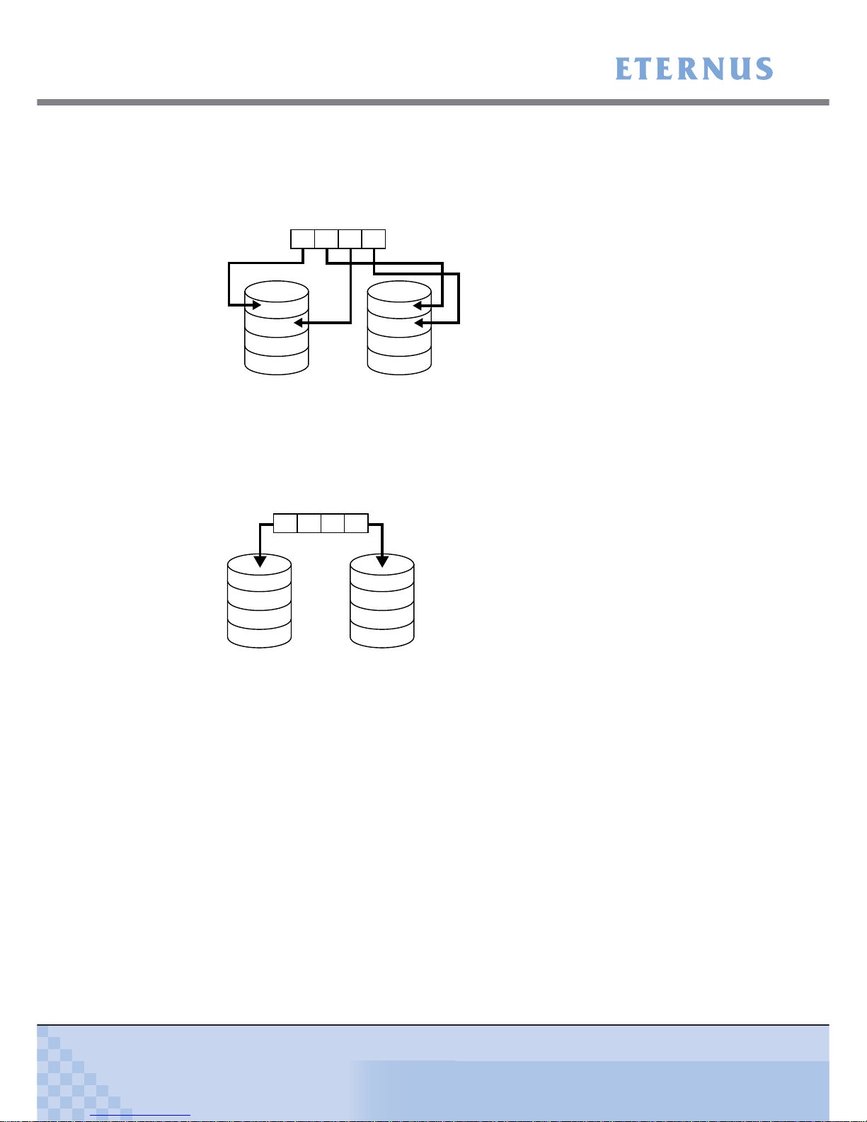
• RAID1 (mirroring)
RAID1 stores the same data on two duplicated disks at the same time.
If one disk fails, other disk continues operation.
Figure 1.2 RAID1 concept
A
C
B
D
Data writing request
HDD0 HDD1
ABCD
A
B
C
D
ABCD
Data writing request
A
B
C
D
HDD0 HDD1
Chapter 1 Overview
> 1.2 Configuration
ETERNUS DX60/DX80/DX90 Disk storage system User Guide
28
Copyright 2010 FUJITSU LIMITED
P3AM-3042-07ENZ0
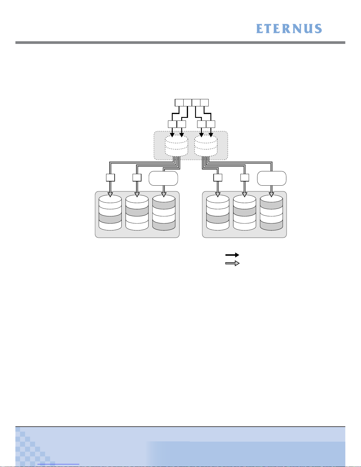
• RAID1+0 (striping of pairs of disks for mirroring)
RAID1+0 combines the performance of RAID0 (striping) with the reliability of RAID1
(mirroring).
Figure 1.3 RAID1+0 concept
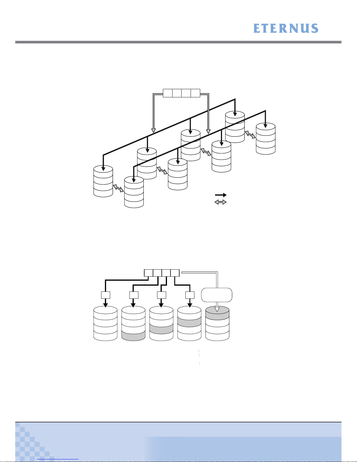
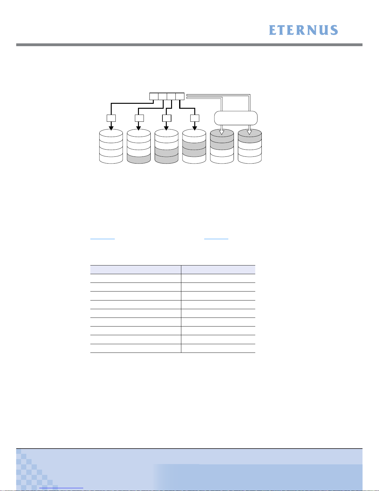
• RAID5 (striping with distributed parity)
Data divided into units of blocks and allocated across multiple disks together with parity
information created from the data. If one disk fails, the remaining data and parity blocks are
sufficient to allow the recovery of the lost data.
Figure 1.4 RAID5 concept
HDD3
HDD7
D
D’
HDD2
HDD6
C
C’
HDD1
HDD5
B
B’
HDD0
HDD4
A
A’
Striping (RAID0)
Mirroring (RAID1)
Data writing request
ABCD
Mirroring
Mirroring
Mirroring
Mirroring
A
E
I
M
ABCD
Data writing request
B
F
J
P
M, N, O, P
C
G
P
I, J, K, L
N
D
P
E, F, G, H
K
O
H
L
P
Create Parity Data
P
A, B, C, D
A B DC
HDD0 HDD1 HDD2 HDD3 HDD4
Parity for data A to D
Parity for data E to H
Parity for data I to L:
Parity for data M to P
Parity M, N, O, P
Parity I, J, K, L
Parity E, F, G, H
Parity A, B, C, D
Chapter 1 Overview
> 1.2 Configuration
ETERNUS DX60/DX80/DX90 Disk storage system User Guide
29
Copyright 2010 FUJITSU LIMITED
P3AM-3042-07ENZ0
• RAID5+0 (double striping with distributed parity)
Multiple RAID5 volumes are RAID0 striped. For large capacity configurations, use of
RAID5+0 instead of RAID5 results in enhanced performance, improved reliability, and shorter
rebuilding times.
Figure 1.5 RAID5+0 concept
Striping with
distributed parity
(RAID5)
Striping (RAID0)
A
E
B
I
F
P
A, B
P
M, N
C
G
H
P
C, D
P
O, P
HDD0 HDD1 HDD2 HDD3 HDD4 HDD5
D
K
P
K, L
Striping (RAID0)
Striping with
distributed parity
(RAID5)
J
L
M
N
O
P
P
E, F
P
I, J
P
G, H
RAID5 RAID5
A B
Create parity data
D
Create parity data
C
Data writing request
A
B
C
D
ABCD
A B C D
Chapter 1 Overview
> 1.2 Configuration
ETERNUS DX60/DX80/DX90 Disk storage system User Guide
30
Copyright 2010 FUJITSU LIMITED
P3AM-3042-07ENZ0
• RAID6 (striping with distributed double parities)
Store two different parities on different disks (double parities) to recover from up to two disk
failures.
Figure 1.6 RAID6 concept
■ User capacity for each RAID level
User capacity varies according to the RAID level.
Table 1.1
shows the user capacity per disk. Table 1.2 shows the formula for calculating the user
capacity for each RAID level.
Table 1.1 User capacity per disk
*1: The above User Capacities are based on a 1MB = 1,0242Byte metric.
P2
M, N, O, P
P2
I, J, K, L
A
E
I
M
ABCD
Data writing request
B
F
J
P1
M, N, O, P
C
G
P1
I, J, K, L
D
P1
E, F, G, H
P2
E, F, G, H
N
K
O
P1
A, B, C, D
H
L
P
P2
A, B, C, D
A B DC
Create parity data
HDD0 HDD1 HDD2 HDD3 HDD4 HDD5
Parity for data A to D: Parity1
A, B, C, D and Parity2 A, B, C, D
Parity for data E to H: Parity1 E, F, G, H and Parity2 E, F, G, H
Parity for data I to L: Parity1 I, J, K, L and Parity2 I, J, K, L
Parity for data M to P: Parity1 M, N, O, P and Parity2 M, N, O, P
Product name User Capacity per Disk (*1)
100GB SSD 92,672MB
200GB SSD 186,624MB
146GB SAS disk 135,936MB
300GB SAS disk 279,040MB
450GB SAS disk 419,072MB
600GB SAS disk 559,104MB
750GB Nearline SAS disk 702,976MB
1TB Nearline SAS disk 937,728MB
2TB Nearline SAS disk 1,866,240MB
 Loading...