

ETERNITY 16, 18, 26, 20, 24 Installation Manual

1
INSTALLATION GUIDE
FOR EXTERNAL INSTALLATION ONLY
Eternity
GAS WATER HEATERS
MODELS 16-18-20-24-2
6

2
CONTENS
IMPORTANT・・・・・・・・・・・・・・・・・・・・・
FOR THE INSTALLER・・・・・・・・・・・・・・・・・
FOR THE SERVICER・・・・・・・・・・・・・・・・・
FOR THE PLUMBER・・・・・・・・・・・・・・・・・
SPECIFICATIONS・・・・・・・・・・・・・・・・・・
INTRODUCTION・・・・・・・・・・・・・・・・・・・
DIMENSIONS AND CONNECTION POINTS・・・・・・・
SAFETY GUIDELINES・・・・・・・・・・・・・・・・
INSTALLATION・・・・・・・・・・・・・・・・・・・
CONFIRM THE APPLIANCE SUITABILITY・・・・・・・・
ABOUT SELECTING
A INSTALLATION LOCATION・・・・・・・・・・・・
CLEARANCES FOR OUTDOOR
HEATER LOCATIONS – AS5601・・・・・・・・・・・
GAS CONNECTIONS・・・・・・・・・・・・・・・・
SIZING AND CONNECTING・・・・・・・・・・・・・・
MEASURING INLET GAS PRESSURE
AND TESTING GAS LEAKGAE・・・・・・・・・・・
WATER CONNECTIONS
・・・・・・・・・・・・・・・
ELECTRICAL CONNECTIONS・・・・・・・・・・・・
REMOTE CONTROLLER・・・・・・・・・・・・・・・
REMOTE CONTROLLER INSTALLATION・・・・・・・・
・
CONNECTION OF REMOTE CONTROLLER
WIRING TO THE WATER HEATER・・・・・・・・・・
2
2
2
3
3
4
5
6
7
7
8
9
10
10
11
12
13
14
15
16
INITIAL OPERATION
・・・・・・・・・・・・・・・
NOMAL OPERATION・・・・・・・・・・・・・・・
WITHOUT REMOTE CONTROLLER・・・・・・・・・
WITH ONLY MAIN
REMOTE CONTROLLER・・・・・・・・・・・・
WITH MULTIPLE REMOTE CONTROLLRE・・・・・・
FREEZE PREVENTION・・・・・・・・・・・・・・
WINTER SHUTDOWN・・・・・・・・・・・・・・・
MAINTENANCE AND SERVICE・・・・・・・・・・
UNIT DRAINING and FILTER CLEANING・・・・・・・
GENERAL TROUBLE SHOOTING・・・・・・・・
PCB ERROR CODES・・・・・・・・・・・・・・・
WIRING DIAGRAM・・・・・・・・・・・・・・・・
OPERATING SAFETY・・・・・・・・・・・・・・・
WATER FLOW AND
WATER TENPERATURE・・・・・・・・・・・・
WARANTY CONDITIONS・・・・・・・・・・・・・
17
18
18
18
19
20
20
21
21
22
24
25
26
28
28
IMPORTANT
This User Guide has been prepared for Installers and Servicers of the equipment. Please keep
it in a safe place for future reference.
FOR THE INSTALLER
The installation must be done in accordance with the information supplied in this User Guide.
All other relevant National, State or Local regulations must also be conformed with and these
include (but are not limited to):
Australian Standard AS3500.1 – Water Supply
Australian Standard AS3498 – Hot Water Supply
Australian Standard AS3000 – Electrical Installation
Australian Installation Code AS5601 – Gas Appliance Installation
Local Water, Gas & Electrical Authority Regulations
Municipal Building Codes
FOR THE SERVICER
Maintenance and fault-finding must be done in accordance with these instructions and the
applicable regulations listed above.
@@@@@@@@@@@WARNING@@@@@@@@@@@
Installation and service must be performed by a qualified installer (for example, a
licensed plumber or gas fitter).
3
FOR THE PLUMBER
PLEASE NOTE this water heater is supplied factory set at 70°C outlet hot water temperature.
This water heater does require a tempering valve to be installed to comply with AS3498
/ 50C requirement.
Please follow all the installation instructions in the Installation and operating instructions
handbook and the following additional instructions for the water heater outlet connection.
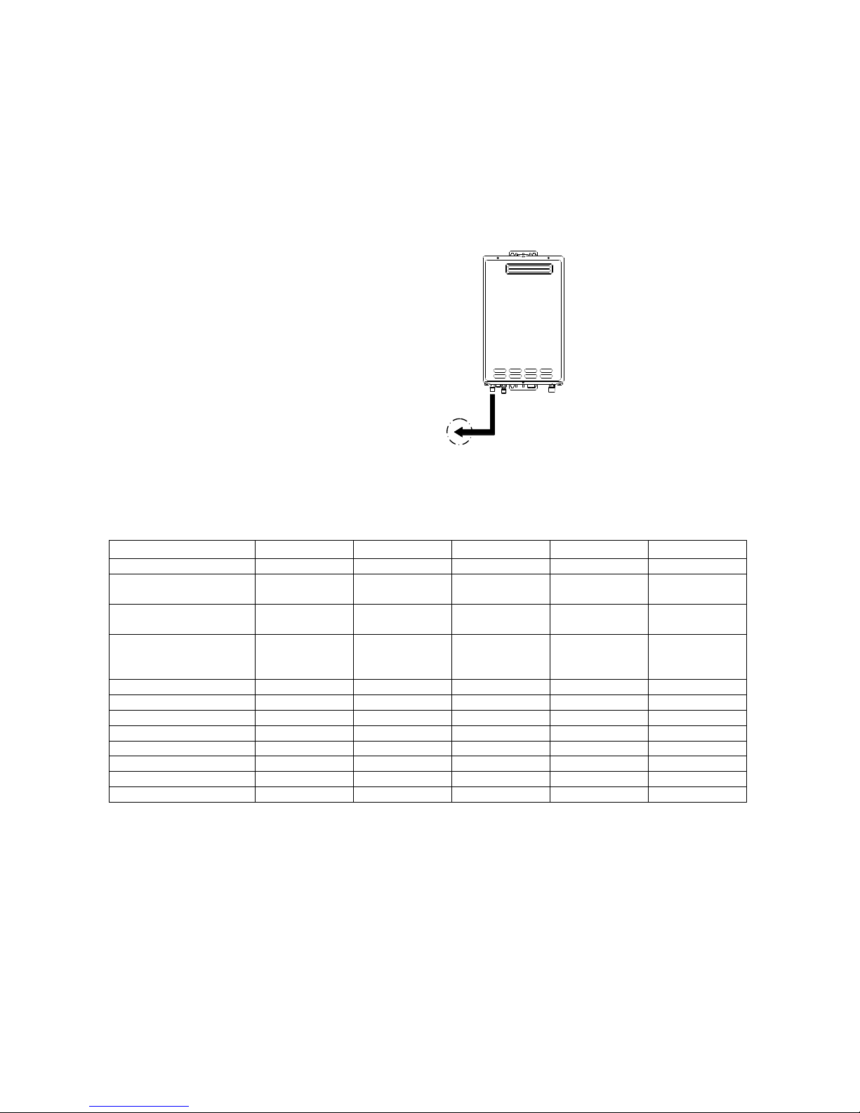
1. When connecting the hot water supply to
the fixtures in the property a minimum of
One (1) Metre of pipework must be used
between the outlet of the water heater and
the first tap and outlet. See Diagram
below.
2. The Hot water line should be insulated
with Ensolex or similar pipe insulation.
3. When the installation is completed the
temperature is to be tested at the taps to
confirm the water temperature does not
exceed the required 50°C setting.
SPECIFICATIONS
MODELS 16 18 20
24 26
Gas Input MJ/h 125 145 160 185 195
Inlet Pressure
kPa – Nat. Gas
1.13 min.
2.75 max.
1.13 min.
2.75 max.
1.13 min.
2.75 max.
1.13 min.
2.75 max.
1.13 min.
2.75 max.
Inlet Pressure
kPa - LPG
2.75 min./max 2.75 min./max 2.75 min./max 2.75 min./max 2.75 min./max.
Water Supply
Pressure
kPa
150* min.
1200 max
150* min.
1200 max
150* min.
1200 max
150* min.
1200 max
150* min.
1200 max.
Height mm 542 542 542 542 542
Depth mm 170 170 170 215 215
Width mm 350 350 350 350 350
Weight kg 15.7 15.7 15.7 17.2 17.2
Gas Connection mm 20 BSP 20 BSP 20 BSP 20 BSP 20 BSP
Water Connections 15 BSP 15 BSP 15 BSP 15 BSP 15 BSP
Ignition Electronic Electronic Electronic Electronic Electronic
Electrical Supply V 240 AC 240 AC 240 AC 240 AC 240 AC
NOTES:
* The appliance will operate at reduced performance below 340 kPa.
For information relating to burner test point pressures and injector sizes refer to the rating
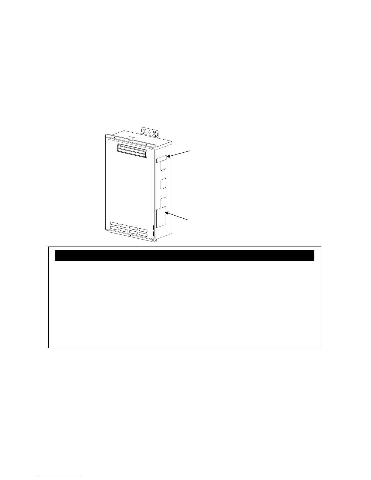
plate located on the right hand side of the cabinet for each model. (please refer to p.7)
For information relating to overall dimensions and connection points refer to diagrams.
(Please refer to p.5)
Before installing in areas over 1500 m above sea level, contact the manufacturer for
instructions.
Total length to first tap
or outlet is required to
be a minimum of 1
meter from the outlet
connection of the water
heater.
Pipe size is nominal
18mm from hot water
outlet to the first tap or
outlet.
First tap or outlet
4
INTRODUCTION
This manual provides information necessary for the installation, operation, and
maintenance of the water heater.
The model description is listed on the rating plate which is attached to the right side of
the case of the water heater. (Please refer to p.7)
Please read all installation instructions completely before installing this product.
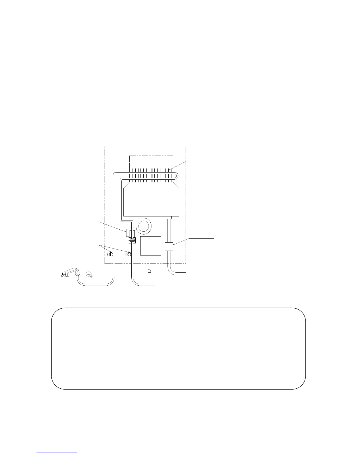
The Water Heater is an instantaneous, tankless water heater designed to efficiently
supply endless hot water for your needs.
The principle behind the water heater is simple:
Burner
Heat exchanger
Exhaust
Flow sensor
Thermistor
Computer
board
AC240V
Gas valve
Fan
Cold water inlet
Gas
Hot water outlet
1. A hot water tap is turned on.
2. Water enters the heater.
3. The water flow sensor detects the water flow.
4. The computer automatically ignites the burner.
5. Water circulates through the heat exchanger and then gets hot.
6. The computer will modulate the gas supply valve and water flow to produce the right
amount of hot water at the correct temperature.
7. When the tap is turned off, the unit shuts down.
※ This diagram illustrates the
water heater design
concepts only and is not
accurate to the one
physical description.
5
GAS
COLD
HOT
GAS
HOT
COLD
133 124
47 GAS
330
350
520
490
37
198
60
94
335
79
19
41 HOT
49 COLD
170
15.7
542
137
31 POWER
POWER
46:COLD
86:GAS
114:HOT
124:POWER
34
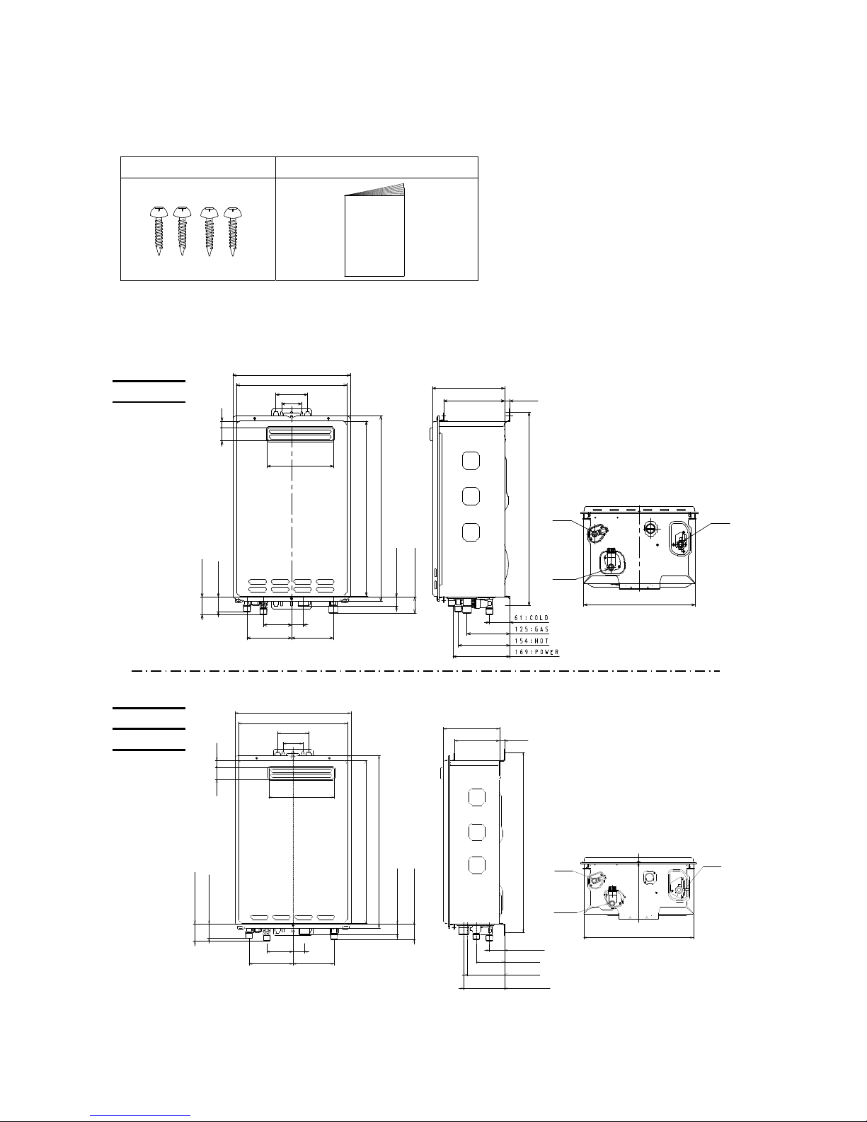
ACCESSORIES
Check that the installation manual and screws are included with the unit.
Screws × 4
Manual
DIMENSIONS AND CONNECTION POINTS
GAS
COLD
HOT
GAS
HOT
COLD
19
37
330
350
490
124133
335
44.5
GAS
520
41 HOT
49 COLD
198
60
94
215
182
542
15.7
84 34
POWER
25 POWER
Model24
Model26
Model16
Model18
Model20
6
SAFETY GUIDELINES
Ensure the following safety instructions are read and understood before commencing
installation.
GENERAL
1. Carefully plan where you intend to install the Water Heater. Please ensure:
The water heater will have enough combustible air and proper ventilation.
Locate the water heater where water leakage will not damage surrounding areas.
2. Check the rating plate and gas type label for the correct GAS TYPE, GAS PRESSURE,
WATER PRESSURE and ELECTRIC RATING.
*If this unit does not match your requirements, do not install and consult with
manufacture.
3. If any problem should occur, turn off all hot water taps and turn off the gas. Then call a
trained technician or the Gas Company or the manufacturer.
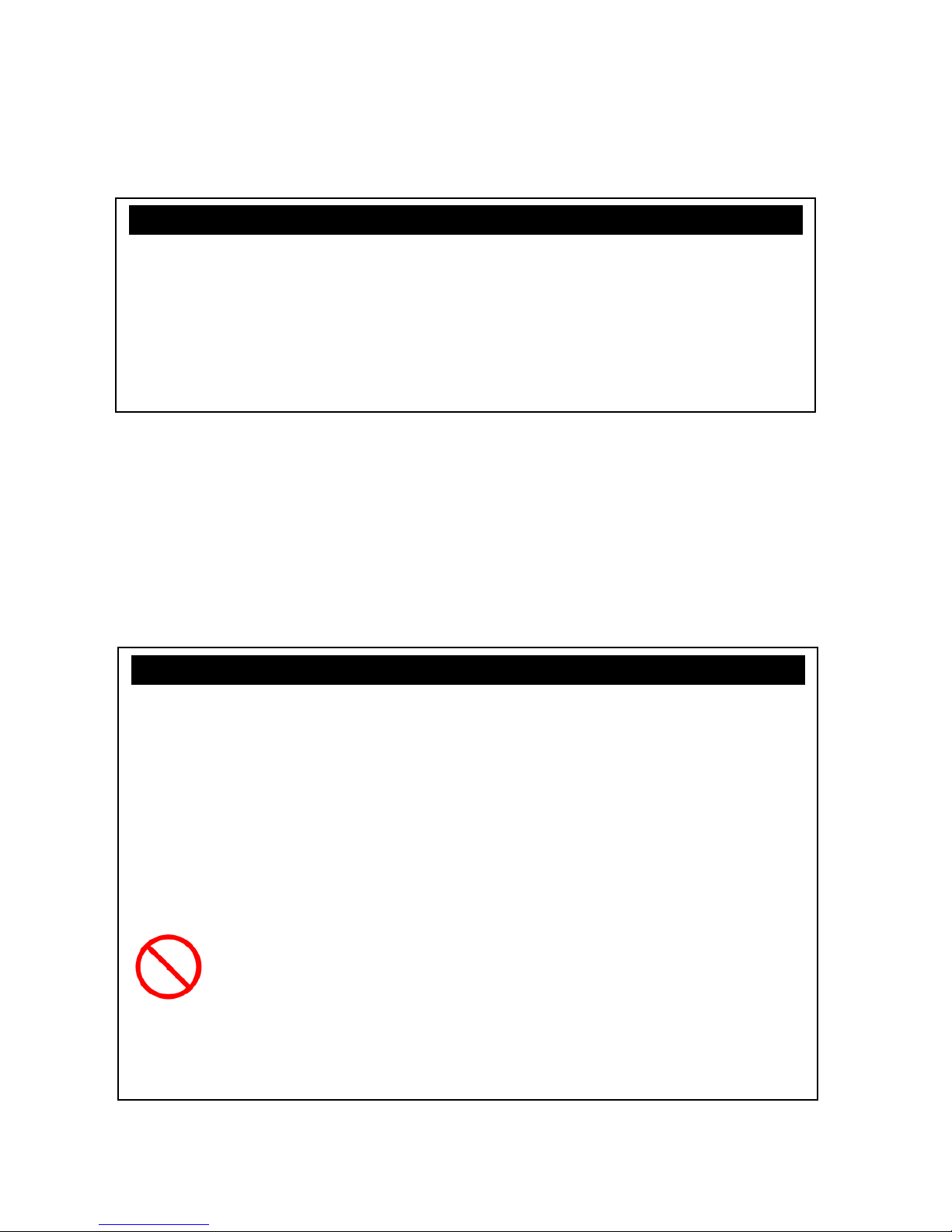
@@@@@@@@@@@WARNING@@@@@@@@@@@
For the continuing safety of this water heater it must be installed and operated and
maintained in accordance with manufactures instructions.
Installation and service must be performed by a qualified installer (for example, a
licensed plumber or gas fitter).
The installer (licensed professional) is responsible for the correct installation of the
water heater and for compliance with all relevant National, State or local
regulations.
The water heater must be installed OUTDOORS ONLY. DO NOT install the
water heater indoors.
@@@@@@@@@@@WARNING@@@@@@@@@@@
Water temperatures above 50 ℃ can cause severe burns or death from scalding.
Children, the disabled and the elderly are at a high risk of being injured. Feel the water
temperature before bathing or showering. Do not leave children, disabled persons, or
the elderly unsupervised. The Australian Standards AS 3498 gives f ull det ails of the
requirements for supply of controlled temperature to ablution outlets (bathrooms) and is
required to be conformed to under all plumbing codes with in Australia.
Do not store or use gasoline or other flammables, vapors, or liquids in the
vicinity of this appliance.
Do not reverse the water and/or gas connections as this will damage the
gas valves and can cause severe injury or death. Follow the diagram on p.
10 and 12 when installing your water heater.
Do not use this appliance if any part has been in contact with or been
immersed in water. Immediately call a licensed plumber, a licensed gas
fitter, or a professional service technician to inspect and/or service the unit if
necessary.
Do not disconnect the electrical supply if the ambient temperature will drop
below freezing. The Freeze Prevention System only works if the unit has
electrical power. The warranty will not be covered if the heat exchanger is
damaged due to freezing. Refer to the section on the Freeze Prevention
System on p. 20 for more information.
Prohibited
7
INSTALLATION
The water heater requires careful and correct installation to ensure safe and efficient operation.
This manual must be followed exactly. Read the “SAFETY GUIDELINES” and the
“IMPORTANT” sections at the beginning of this manual.
CONFIRM THE APPLIANCE SUITABILITY
Check the gas type label and the rating plate for the correct gas type, gas pressure, water
pressure and electrical rating for your application. Do not install this unit if these requirements
can’t be met.
The manifold pressure is preset at the factory. It is computer controlled and should not
need adjustment.
Occupants are advised of any inconveniences which could occur such as disconnection of
services.
You follow the electrical earthing procedure outlined in AS3500.4 before cutting or
uncoupling existing metallic pipework.
It should be as close as practical to the hot water outlets to minimise heat loss and cost.
The water heater does not require a fireproof back plate if installed on timber wall.
Rating Label Position
on Cabinet
Gas Type Label
Position on Cabinet
@@@@@@@@@@@CAUTION@@@@@@@@@@@
This equipment is not suitable for pool or spa heating.
Water hardness may affect the water heater. It may be damaged.
It is important that the water heater is installed in water conditions that are suitable for
its efficient, long use.
This is a water heating apparatus only and the final fitness of water delivered is
dependent upon the quality of water supplied to this system.
The connection, attachment, integration or general association of other equipment or
parts not specified by the water heater which either directly or indirectly affect the
operation or performance of this equipment – could void the warranty.

8
ABOUT SELECTING A INSTALL ATION LOCATION
Carefully read this section before installing, and when you select the location for install the
water heater, you must follow these precautions exactly.
You check the proximity of gas & electrical lines so as not to create a hazard and avoid
access problems for other services.
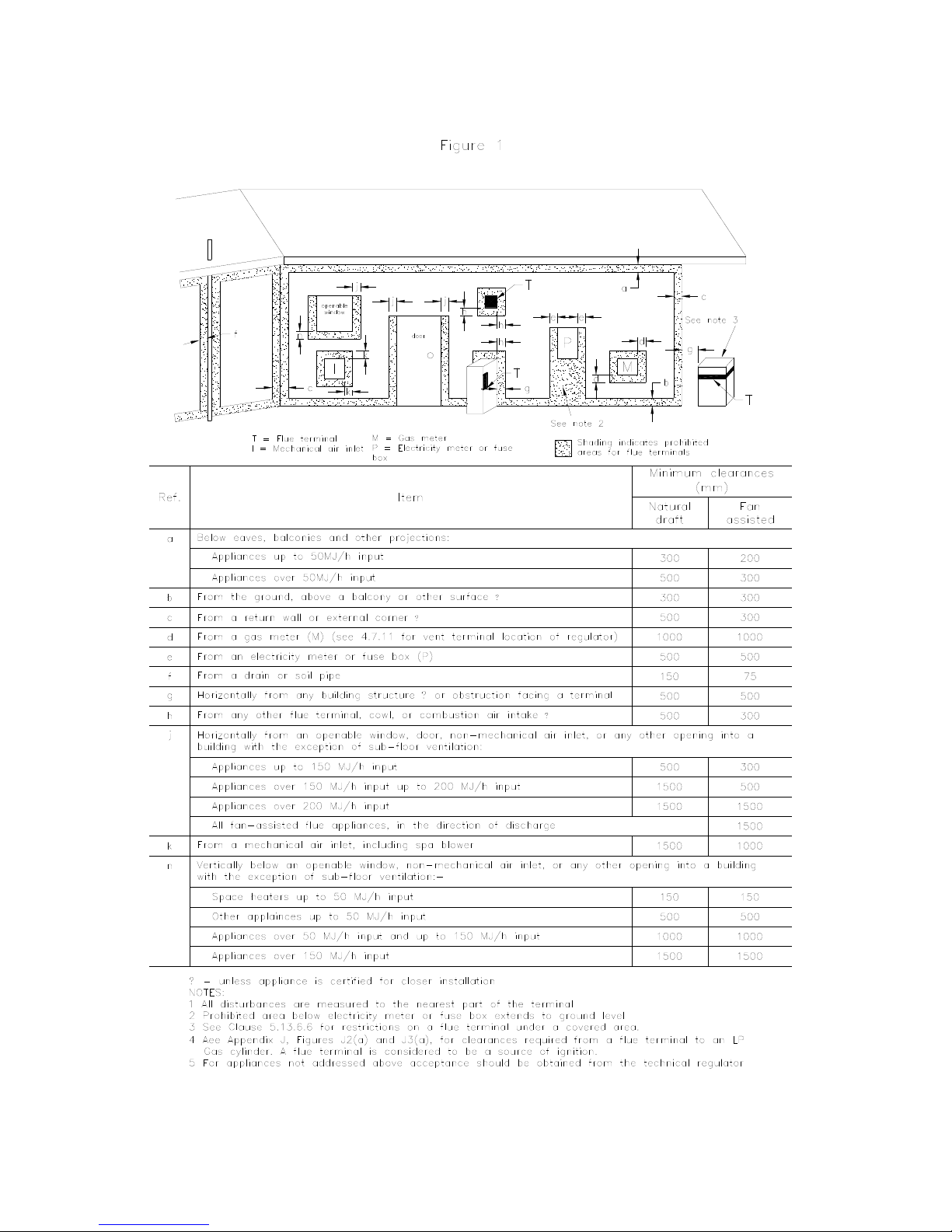
It must be located in accordance with the requirements of AS5601 and have sufficient
clearances from eaves, windows, vents etc. – see the diagram on the p.11.
“Exemption from Prescribed Statutory Requirement”: AS5601-2000 Clause 5.13.6.5, This
relates to the physical separation distance specification where multiple appliances are
employed. That equates to a minimum 150mm horizontal flue separation distance allowing
appliances to be placed side by side in the same vertical plane
Most load bearing walls such as brick, brick/veneer, weatherboard and stud-frames are
suitable locations.
Sec urely fasten the unit to the wall with screws or bolts in the top and bottom brackets. A
minimum of two top and bottom must be used.
@@@@@@@@@@@CAUTION@@@@@@@@@@@
This is a water heating apparatus only and the final fitness of water delivered is
dependent upon the quality of water supplied to this system.
Although the water heater is designed to operate with minimal sound, you should not
install the unit on a wall adjacent to a bedroom, or a room that is intended for quiet
study or meditation, etc.
Locate your heater close to a drain where leakage will not do damage to surrounding
areas. As with any water heating appliance, the potential for leakage at some time in
life of the product dose exist.
@@@@@@@@@@@WARNING@@@@@@@@@@@
Every care is taken to warn occupants of the building and the public of any injury that
may occur from falling tools, open trenches, water connections or any other general
hazard.
Make sure the water heater will have enough combustion air and proper ventilation.
Keep the area around the water heater clean. Particles may clog the air vent, reduce
fan function, or cause improper combustion.
Locate unit for easy access and maintain proper space for service and maintenance.
Install the unit so that it can be connected or removed easily.
The water heater must be installed outdoors only. Do not install the water heater
indoors.
Do not locate your water heater in a pit or any location where gas and water can
accumulate.
9
CLEARANCES FOR OUTDOOR HEATER LOCATIONS – AS5601
*Exemption from prescribe stat utory requirements referred to in Figu re 1 has been granted
to allow multiple series of the Wate r Heaters to be positioned side by side.
 Loading...