

LAMP REPLACEMENT:
LED non replaceable.
REPLACEMENT BATTERY TYPE:
Type - Ni cad 3.6V 3 cell 1500Ah complete with LED strip.
BATTERY REPLACEMENT:
If after routine operation checks, the LEDs do not remain lit for the three hour period, a new battery pack may
be required.
Switch o the electricity at the mains.
Allow batteries to fully discharge then reconnect to supply and allow charging for 24 hours.
Test again for 3 hours, if light does not remain lit change the battery pack as follows:
01) Isolate the mains supply to the unit.
02) Remove the front cover disconnect tting and remove.
03) Unplug the battery leads from LED strip.
04) Remove the two screws in the back of the exit box case that retain the battery pack.
05) Write current date on the new battery pack.
06) Fit new battery pack securing in place using the screws removed from the old pack.
07) Reconnect battery plug.
08) Replace cover.
09) Restore power and allow charging for 24 hours.
10) Perform full operation check and update test record.
EVENTUALLY, YOU MAY WANT TO REPLACE THIS PRODUCT:
Regulations require the recycling of Waste from Electrical and Electronic Equipment (European “WEEE
Directive” eective August 2005—UK WEEE Regulations eective 2nd Januar y 2007). Environment Agency
Registered Producer: WEE/GA0248QZ.
WHEN YOUR PRODUCT COMES TO THE END OF ITS LIFE OR YOU CHOOSE TO REPLACE IT, PLEASE RECYCLE IT
WHERE FACILITIES EXIST DO NOT DISPOSE WITH HOUSEHOLD WASTE.
IF YOU EXPERIENCE PROBLEMS:
If you believe your product is defective, please return it to the place where you bought it. Our Technical Team
will gladly advise on any Eterna Lighting product, but may not be able to give specic instructions regarding
individual installations.
For breakage information visit: www.eterna-lighting.co.uk
INSTALLATION INSTRUCTIONS
A guide for qualied electricians
Pack contents:
1 x LED Exit box
1 x Instruction leaet
Model:
1 x Maintenance check
EXIT3MLED
record
Issue 2013
FOR PRODUCT ADVICE:
• T: 01933 673 144
• F: 01933 678 083
• E: sales@eterna-lighting.co.uk
Visit our website:
www.eterna-lighting.co.uk
Maintained LED Exit Box
Duration: 3 hours duration in emergency mode
These instructions are provided as a guideline to assist you.
PLEASE READ THESE INSTRUCTIONS BEFORE INSTALLATION
AND RETAIN FOR FUTURE REFERENCE
READ THIS FIRST:
Check the pack and make sure you have all of the
parts listed on the front of this booklet. If not,
contact the outlet where you bought this product.
This light tting must be installed by a competent
person in accordance with the current building and
IEE wiring regulations.
As the buyer, installer and/or user of this product it
is your own responsibility to ensure that this tting
is t for the purpose for which you have intended
it. Eterna Lighting cannot accept any liability for
loss, damage or premature failure resulting from
inappropriate use.
Switch o the mains before commencing installation
and remove the appropriate circuit fuse or lock o
MCB.
Disconnec t from the electrical supply before ash or
high voltage testing.
This unit is suitable for indoor use only.
This product is suitable for installation in surfaces
with normal ammability e.g. wood, plasterboard,
and masonry. It is not suitable for use on highly
ammable sur faces (e.g. polystyrene, textiles).
Before making xing holes, check that there are no
obstructions hidden beneath the mounting surface
such as pipes or cables
Do not install into surfaces which are damp, freshly
painted or otherwise electrically conductive (e.g.
metallic surfaces).
This product is designed for permanent connection
to xed wiring: this should be a suitable circuit
(protected with the appropriate MCB or fuse).
When making connections, ensure that the terminals
are tightened securely and that no strands of wire
protrude. Check that the terminals are tightened
onto the bared conductors and not onto any
insulation.
This product must be connected to earth
termination.
IMPORTANT - Always switch o mains power before
opening tting.
You are advised at every stage of your installation to
double-check any electrical connections you have
made. After you have completed your installation
there are electrical tests that should be carried out:
these tests are specied in the Wiring Regulations
(BS7671) referred to in the Building Regulations.
CLEANING:
Clean this emergency exit sign tting only with a soft
dry cloth.
The PC legend may be removed and washed in a
mild detergent solution make sure it is completely
dry before putting it back on your light tting.
Do not use any chemical or abrasive cleaners.
OPERATION CHECKS:
Periodic testing should be carried out monthly by
simulating a failure of supply, causing the tting to
be energised from its battery. Interruption of the
supply should be carried out by the operation of a
local key switch or other isolation device. During this
period all ttings should be examined visually to
ensure that they are functioning correctly. At the end
of the test period the supply shall be restored and all
indicator lamps or devices checked to ensure that the
normal supply has been restored.
The duration of the simulated failure shall be:-
Each month:
Isolate the power supply and check the light is
illuminated.
This test should last for no more than 45 minutes.
Endorse the test record form supplied.
Once each year:
Isolate the power supply and check that the light is
still illuminated after 3 hours. Endorse the test record
form.
Installation, maintenance and operation
check record SHEET INCLUDED
INSTALLATION:
01) Switch o the mains before commencing
installation and remove the appropriate circuit
fuse or lock o MCB.
02) Choose the location for your emergency tting
giving consideration to all of the points above.
03) Undo the 2 screws on the bottom of front cover
and lift o and remove legend.
04) Using the tting as a template mark the xing
points on the mounting sur face.
05) Drill and plug holes as appropriate.
06) Thread cable through entry point and into
tting.
07) Secure and x to mounting sur face.
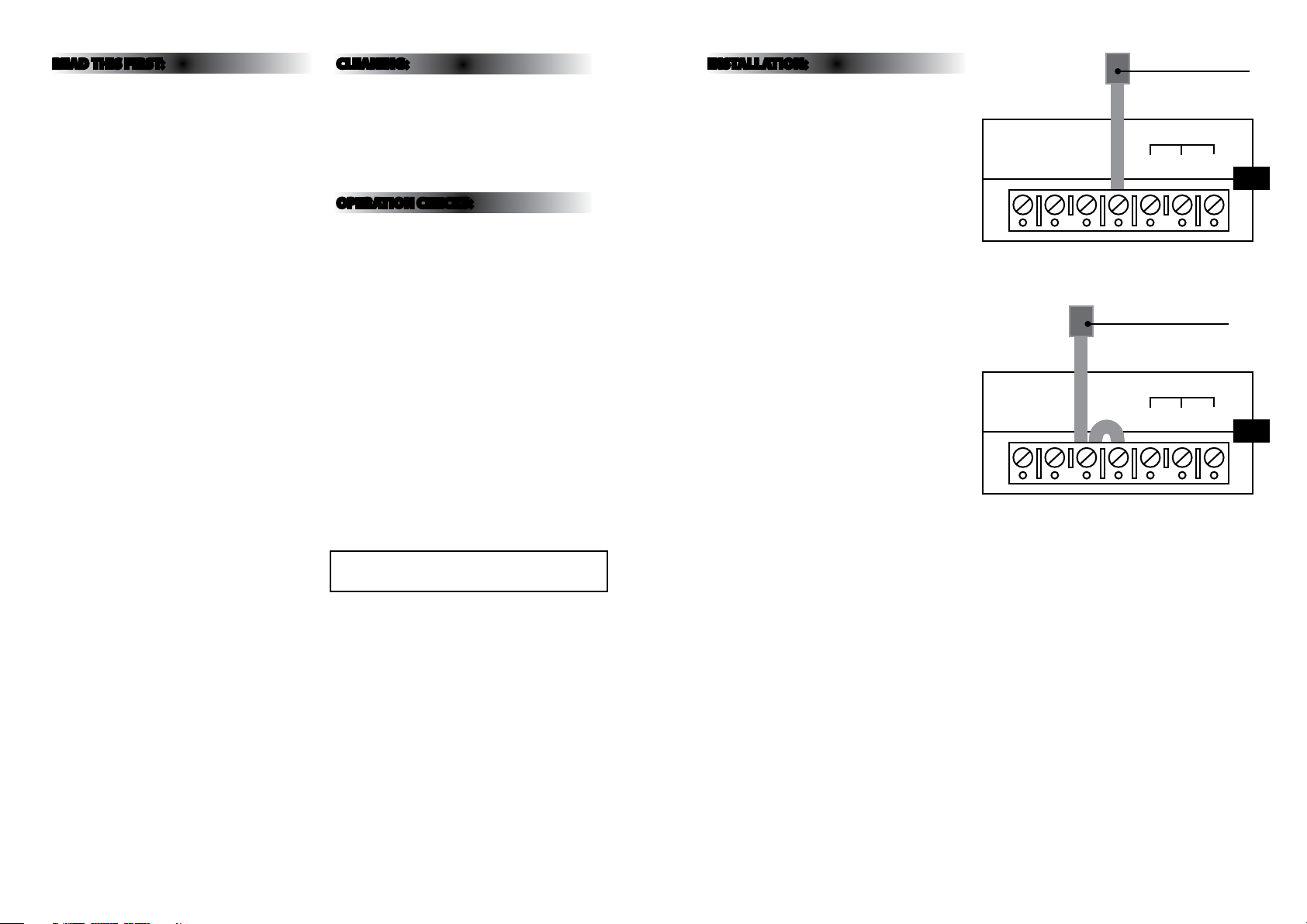
08) Make connection to the mains supply according
to the terminal markings. An un-switched 230v
A.C. supply must be connected to the live (L),
Earth (E) and Neutral (N) terminals on the PCB
board. See Fig. 1 opposite.
09) For maintained operation, connect an additional
switched mains supply to the L-sw terminal
(See Fig. 1) or alternatively link across L & L-sw
unswitched mains terminals to operate as a
maintained unit. See Fig. 2 opposite.
10) Plug the batter y / LED lead into connector
mounted on LED strip.
11) Ret legend and secure front frame with the 2
screws.
12) Restore AC supply and check operation ensuring
the Green charging light is on.
13) There is a test switch that can be pressed to
ensure battery and LED are working.
AC230-240V 50HZ
N E L Lsw + - +
Un-Switched Mains Cable
AC230-240V 50HZ
N E L Lsw + - +
Switched Mains Cable
BATTERY LED
Fig 1
BATTERY LED
Fig 2
 Loading...