

Page 1
Pack contents:
Spotlight qty.1
Gasket for PAR 38 lamp qty.1 (per head)
Gasket for PAR 20 lamp qty.1 (per head)
CLEANING:
1. Clean thi s light fi tting o nly wi th a sof t dry cl oth.
2. Do not u se any ch emical o r abrasi ve clean ers.
LAMP REPLACEMENT:
1. Switch of f the electri city a t the main s.
2. Remove a nd replac e lamp.
EVENTUALLY, YOU MAY WANT TO REPLACE THIS LIGHT FITTING:
When your l ight fit ting comes to the en d of its li fe or you c hoose to u pdate or up grade it b y replac ing it,
please do n ot disp ose of it w ith your n ormal ho usehol d waste , and pleas e recy cle wher e facili ties ex ist .
When you ne ed to dis pose of t his ligh t fitti ng, che ck wit h your suppl ier or loc al authority f or suit able
option s. New re gulat ions req uire the re cycl ing of Was te from El ectr ical and E lect ronic Equ ipment
(Europe an “W EEE Dire ctiv e” ef fecti ve Augu st 2005 —UK WEEE Regul ations e ffec tive 2nd Januar y 2007) .
Enviro nment Ag ency Re giste red Prod ucer: W EE/G A0248QZ
IF YOU EXPERIENCE PROBLEMS:
If your lig ht fitt ing is de fect ive or dev elops a fau lt, ple ase ret urn it to th e place wh ere you bou ght it . You
can cal l our Helpl ine for ad vice. T he Helpline will g ladly gi ve advi ce on any as pect o f any Eter na produ ct.
SPECIFICATION:
WATTAGE : 100W Max
SUPPLY VOLTAGE : 230V - 50H Z
TYP E: PAR3 8 / PAR20
SAFETY AND INSTALLATION INSTRUCTIONS
110427-BT
HELPLINE:
• T: 01933 673 144
• F: 01933 678 083
• E: sales@eterna-lighting.co.uk
For answers to fre quentl y asked
questions (FAQs) and other
information visit our website:
www.eterna-lighting.co.uk
These instructions are provided as a guideline to assist you.
PLEASE READ THESE INSTRUCTIONS BEFORE USING YOUR SPOTLIGHT
PLEASE RETAIN FOR FUTURE REFERENCE
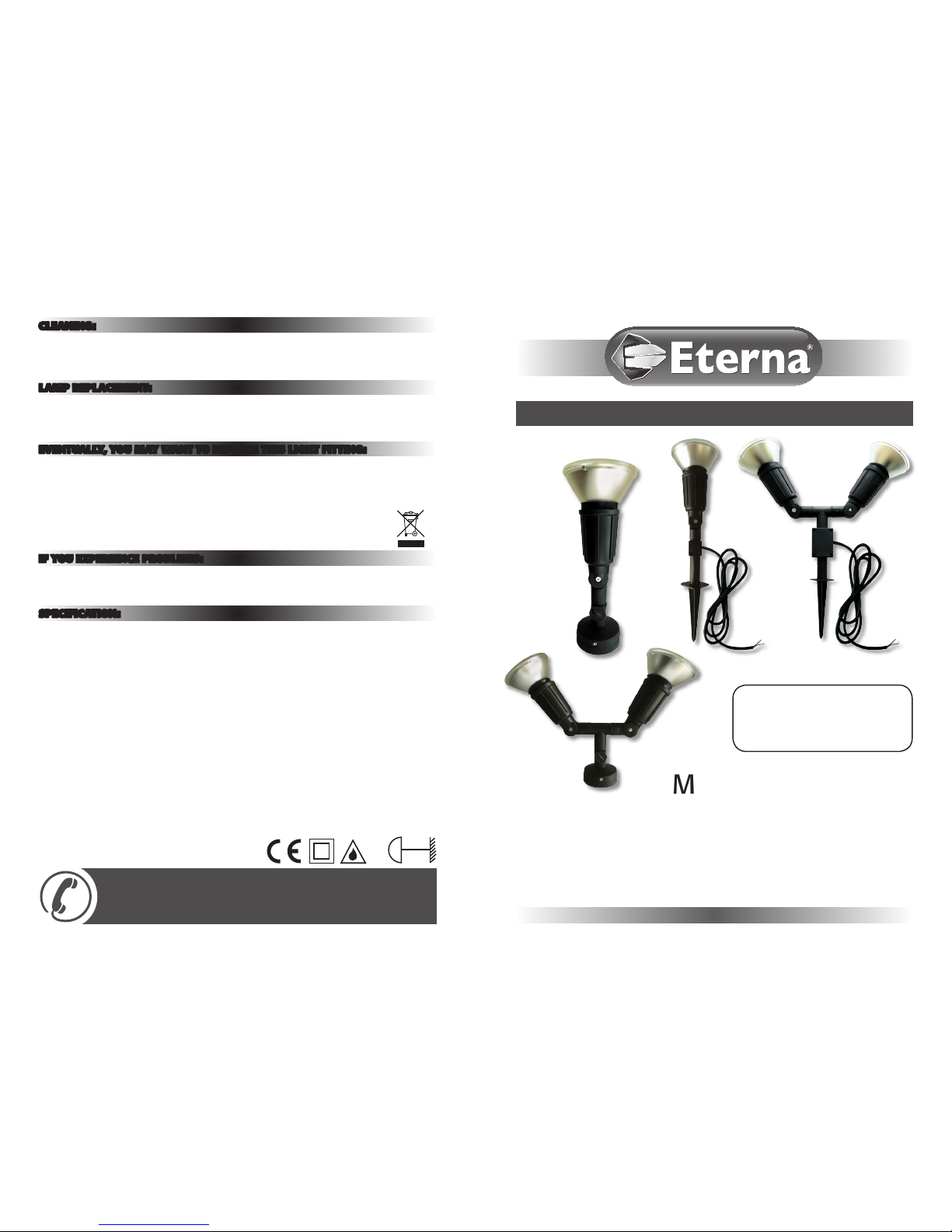
Model:
WB1, WB2, GS1, GS2
Wall/Spike Garden Spotlight
IP44
0.8m
WB1
WB2
GS1
GS2
Page 2
READ THIS FIRST:
Check th e pack and ma ke sure you ha ve all of th e
part s liste d on the fro nt of this b ookle t. If not ,
contac t the outlet wher e you bough t this pro duct .
This lig ht fitt ing mus t be inst alled by a c ompete nt
perso n in accord ance wi th the Bui lding
Regulat ions mak ing reference to th e curren t
editio n of the IE E Wirin g Regulat ions ( BS7671).
The Buil ding Regu lation s may be obt ained from
OPSI (O ffic e for Publi c Sect or Infor mation )
or the depa rtme nt of Comm unitie s and Loc al
Govern ment and v iewed a nd downl oaded fr om
ww w.commun ities .gov.uk followin g the link f or
Buildin g Regula tions .
As the bu yer, inst aller an d/or us er of this p roduc t
it is your o wn resp onsibi lity t o ensure t hat this
fitti ng is fit for t he purpo se for wh ich you hav e
intende d it. Et erna Lig hting c annot ac cept any
liabili ty for l oss, da mage or prem ature fa ilure
result ing from i napprop riate us e.
If in any d oubt, co nsult a q ualifie d elect ricia n.
This pro duct is d esigne d and con struc ted
accordi ng to the pr incipl es of the ap propria te
Briti sh Stand ard and is i ntende d for norma l
domest ic ser vice . Use of th is is fit ting in an y
other en vironm ent, for e xample w here pro longed
period s of use ma y be expe cted an d/or high er
than nor mal ambie nt tempe rature s, may res ult in
a foresho rten ed work ing life .
Swit ch off t he mains be fore com mencin g
insta llatio n and remov e the appro priate c ircui t
fuse.
When wo rking a t height s, plea se use a su itable
platf orm.
Suita ble for ou tdoor us e.
This pr oduct i s suita ble for in stalla tion on s urfac es
with no rmal flamm abilit y (indicated b y the “F ” in
a triang le) e.g. w ood, pla sterb oard, ma sonr y.
Before ma king fix ing hole (s), check tha t there are
no obstr ucti ons hidd en benea th the mou nting
surfac e such as p ipes or c ables .
Make sur e that the fi xings a re stro ng enough t o
suppor t the con sidera ble weigh t of the fit ting and
hold it ri gidly.
If the lo catio n of your ne w fitti ng requi res the
provis ion of a new e lect rical s upply, the s upply
must con form wi th the re quireme nts of t he
Buildin g Regula tions ma king ref erence t o the
curren t editi on of the IE E Wirin g Regula tions
(BS7671).
This pr oduct i s desig ned for pe rmanen t
connec tion to fi xed wir ing. Th is shoul d be a
suitab le circu it prote cted w ith an RCD 3 0ma tri p.
Make conn ectio ns to the el ectr ical su pply in
accorda nce wit h the foll owing c ode:
The core s in the mai ns lead are c oloure d in
accorda nce wit h the foll owing c ode:
Live - Bro wn or Red
Neutra l - Blue or Bla ck
When mak ing conn ectio ns, ens ure that t he
termina ls are tig htene d secure ly and tha t no
strand s of wire pr otrud e. Chec k that the te rminal s
are tigh tened on to the bare d conduc tors and not
onto any in sulat ion. Wrap l oose ter minal blocks
well wit h insula ting ta pe.
This fi ttin g is double i nsulat ed; do no t connec t
any par t to eart h.
WARNING:
• The la mp surf ace bec omes ver y hot after
prolonge d perio ds of use
• Thi s produc t is not in tended to b e used by
childre n and per sons wi th sens ory, phy sical
and/or me ntal imp airmen ts that w ould pre vent
them fro m using it s afely.
• Small c hildre n should b e super vise d to ensur e
that the y do not play w ith thi s light fi ttin g.
IMPOR TANT - Al ways sw itch off mains p ower
before c hanging t he lamp.
• If the e xter nal flex ible cab le of this l uminair e
is damage d it shall b e exclus ively r eplace d by
qualifi ed elec trici an.
• You are ad vised a t ever y stage o f your
insta llatio n to double -check any elec trical
connec tions y ou have mad e. Aft er you have
complet ed your in stall ation th ere are el ectr ical
tests t hat shou ld be car ried ou t: thes e test s are
speci fied in the W iring Re gulat ions (B S7671)
referr ed to in the B uilding R egulat ions. I f in
doubt, c onsult a q ualifi ed elec trici an.
General Information and Safety Instructions:
Installation:
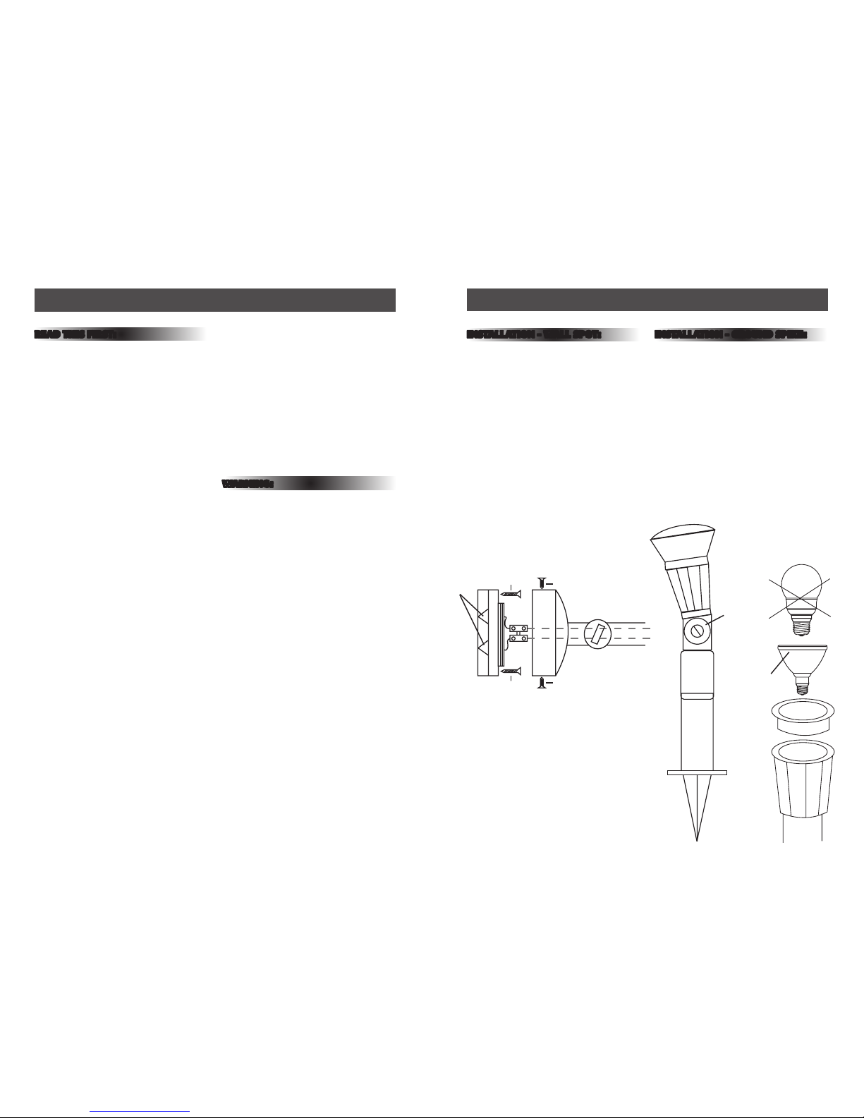
INSTALLATION - WALL SPOT:
1) Loosen t he two s crews m arked A in fig . 1
suffi cientl y to be able t o separa te the bas e
plate fro m the bot tom of th e fitti ng. Take care
not to los e the inte rnal nut s that th e screw s fit
into.
2) Using t he base pl ate as a tem plate mar k the
fixing ho les on the m ountin g surfa ce.
3) If nec essar y drill the holes o n the mount ing
surfac e and ins ert t wo suit able wall p lugs (no t
supplie d).
4) Make a ho le in the gr ommet ju st big eno ugh
for the inc oming mai ns cabl e, and fee d the
incomin g mains ca ble thro ugh the gr ommet.
5) Inse rt gro mmet int o cable en try ho le in the
base pla te and fit ba se plate to m ountin g
surfac e using t wo suitable scr ews (no t
supplie d).
6) Conn ect th e incomin g main cab le Live :
Brown or R ed to the te rminal bl ock mar ked L
obser ving th e connec tion code above.
7) Replac e the fit ting ove r the bas e plate ta king
care not t o damage the c ables and retigh ten
the two s crews m arked A in F ig. 1 belo w:
8) Fit t he appro priate la mp gaske t to the fro nt of
the fitt ing. Ens ure that t he gaske t is corre ctl y
seated t o preven t ingres s of mois ture.
9) Ins ert app ropria te PAR 20 or PAR 38 l amp to
100W maxi mum and sc rew cloc kwi se to sec ure
in fitt ing (as fig. 3).
10) The ang le of the si ngle and t win wall spots
can be adj usted b y loosen ing the ad juster
knob and s crew on th e neck of th e fitt ing, E
(see fig. 2 ) posit ioning th e lamps an d
re-ti ghteni ng.
11) Replace the circ uit fus e, res tore the po wer
supply an d swit ch on.
INSTALLATION - GROUND SPIKE:
1) This fit ting comes with a 2 m mains lea d and
should be c onnec ted to the m ains sup ply usin g
a waterp roof con necti on box (no t supplie d).
2) Use c able appro priate t o your plan ned
insta llatio n, refer t o Buildi ng / Wiri ng
Regulat ions fo r speci fic inst ruct ions for o utdoor
elect rical i nsta llatio ns.
3) Pre ss the spi ke into the s oil or ot her sof t
surfac e in your c hosen lo catio n and adju st
posit ion of the he ad as per fig : 2 E.
4) Route t he cabl e to your mai ns suppl y
connec tion en suring t hat the c able is no t
posit ioned wh ere it is li kely to be d amaged.
5) Replac e the cir cuit fu se, res tore the p ower and
switc h on.
PAR 38
Max 100W
Fig. 2
E
Fig. 1
C
A
A
B
B
L
N
Fig. 3
 Loading...