

Eterna TUS6NL, TUS16NL, TUS10NL, TUS20NL Installation Instructions Manual
Issue 2015
Model:
TUS6NL / TUS10NL / TUS16NL / TUS20NL
Ultraslim Link Triphosphor Fitting
These instructions are provided as a guideline to assist you.
PLEASE READ THESE INSTRUCTIONS BEFORE INSTALLATION
AND RETAIN FOR FUTURE REFERENCE
FOR PRODUCT ADVICE:
• T: 01933 673 144
• F: 01933 678 083
• E: sales@eterna-lighting.co.uk
Visit our website:
www.eterna-lighting.co.uk
INSTALLATION INSTRUCTIONS
A guide for qualied electricians
EVENTUALLY, YOU MAY WANT TO
REPLACE THIS PRODUCT:
Regulations require the recycling of Waste from
Electrical and Electronic Equipment (European
“WEEE Direc tive” eective August 20 05—UK
WEEE Regulation s eective 2nd January 20 07).
Environment Agenc y Registered Producer : WEE/
GA0248Q Z.
WHEN YOUR PR ODUCT COMES TO TH E END OF
ITS LIFE OR YO U CHOOSE TO REPLACE I T, PLEA SE
RECYCLE IT W HERE FACILITIES E XIST DO NOT
DISPOSE WITH HOUSEHOLD WASTE.
CLEANING:
Clean this light t ting only with a soft dr y cloth.
Do not use any chemic al or abrasive cleaners.
IF YOU EXPERIENCE PROBLEMS:
If you believe your p roduct is defective, p lease return
it to the place where yo u bought it. Our Technical
Team will gladly advise on any Eterna Lighting
product, bu t may not be able to give specic
instructions regarding individual installations.
For breakage inf ormation visit:
www.eterna-lighting.co.uk
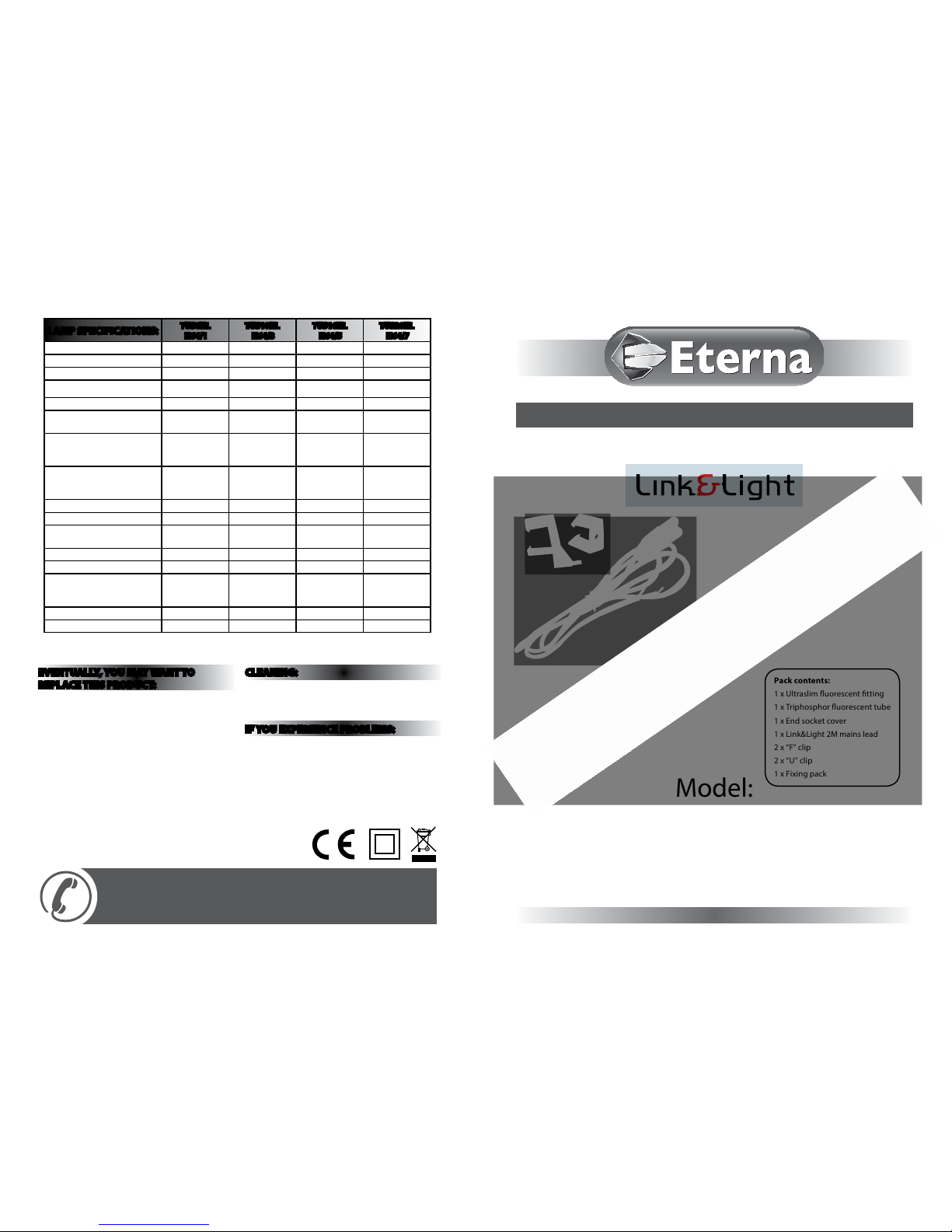
Pack contents:
1 x Ultraslim uorescent tting
1 x Triphosphor uoresce nt tube
1 x End socket cover
1 x Link&Light 2M mains l ead
2 x “F” clip
2 x “U” clip
1 x Fixing pack
LAMP SPECIFICATIONS:
TUS6NL
N64/1
TUS10NL
N64/3
TUS16NL
N64/5
TUS20NL
N64/7
Nominal Wattage 6W 10W 16W 20W
Rated Wattage 6W 10W 16W 20W
Average lifetime hours 10,000 hrs 10,000 hrs 10,000 hrs 10,000 hrs
Nominal useful luminous ux
378 lm 630 lm 1090 lm 1500 lm
Rated luminous ux 378 lm 630 lm 1090 lm 1500 lm
Luminous ecacy (Lm/W) in
50Hz operation
63 63 67 75
Rated lamp Lumen
maintenance
2000hrs: 95%
4000 hrs: 92%
8000 hrs: 90%
2000hrs: 95%
4000 hrs: 92%
8000 hrs: 90%
2000hrs: 95%
4000 hrs: 92%
8000 hrs: 90%
2000hrs: 95%
4000 hrs: 92%
8000 hrs: 90%
Rated survival factors
2000hrs: 99%
4000 hrs: 97%
8000 hrs: 90%
2000hrs: 99%
4000 hrs: 97%
8000 hrs: 90%
2000hrs: 99%
4000 hrs: 97%
8000 hrs: 90%
2000hrs: 99%
4000 hrs: 97%
8000 hrs: 90%
Lamp dimensions (mm) 220mm 341mm 468mm 567mm
Cap type T4 T4 T4 T4
Lamp Mercury content to an
accuracy of 0.1mg
<2mg <2mg <2.5mg <2.5mg
Colour rendering index Ra 83.2 82.9 81.8 82.5
Colour temperature 3400K 3400K 3400K 3400K
Ambient temperature required
to achieve maximum luminous
ux
25°C 25°C 25°C 25°C
Dimmable No No No No
Ballast EEI A2 A2 A2 A2
Made in China
READ THIS FIRST:
Check the pack an d make sure you have all of the par ts
listed on the fr ont of this booklet. I f not, contact the
outlet where you bought this product.
This produc t contains glass, care mus t be taken when
assembling, tting or handling to prevent personal
injury or dama ge to the product.
This light tt ing must be installed by a co mpetent
person in accor dance with the Building R egulations
making refe rence to the current editio n of the IEE Wiring
Regulations (B S7671). The Buildin g Regulations may be
obtained fr om HMSO or viewed and down loaded from
www.communities.gov.uk following the link for Building
Regulations.
As the buyer, insta ller and/or user of this prod uct it is
your own respons ibility to ensure that thi s tting is t
for the purpos e for which you have intended i t. Eterna
Lighting canno t accept any liability for l oss, damage or
premature failure resulting from inappropriate use.
This produc t is designed and constr ucted according to
the principles of the appropriate British Standard and
is intended for n ormal domestic ser vice. Use of this
tting in any other environment, for example where
prolonged periods of use may be expected and/or
higher than nor mal ambient temperatu res, may result in
a foreshortened working life.
The lamps (tubes) sup plied with this ttin g are
consumable par ts and therefore may b e outside of any
warranty oered.
Disconnec t the tting from the el ectrical supply b efore
ash or high volta ge testing.
Suitable for indoor use only.
This produc t is suitable for use in liv ing areas, and
Bathroom dr y (Outside) Zones only (see d iagram below
and current IEE W iring Regulations for d etails). It is
not suitable f or Bathroom Zones 0, 1, 2, or other ar eas
where contac t with moisture is likely. If b eing tted in a
bathroom a 30m A RCD must be used.
This produc t is suitable for instal lation on surfaces wi th
normal ammab ility (indicated by th e “F” in a triangle)
e.g. wood, plas terboard, masonr y. It is not suitable for
use on highly am mable surfaces (e.g. po lystyrene,
textiles).
Before maki ng xing hole(s), check that the re are no
obstructions hidden beneath the mounting surface such
as pipes or cabl es.
The chosen location of your new tting should allow
for the produc t to be securely mounte d and safely
connected to t he mains supply.
Do not attach t o surfaces which are damp, f reshly
painted or otherwise electrically conductive (e.g.
metallic surfaces).
If the locatio n of your new tting requ ires the provision
of a new elect rical supply, the supply mus t conform
with the requirements of the Building Regulations
making refe rence to the current editio n of the IEE Wiring
Regulations (BS7671).
This produc t is designed for perma nent connection to
xed wiring: thi s should be either a suita ble lighting
circuit (prote cted with a 5 or 6 Amp MCB or fus e) or a
fused spur (with a 3 A mp fuse) via a fused connec tion
unit. We recomme nd that the supply incorp orates a
switch for ease o f operation.
The cores in the ma ins lead are coloured in acco rdance
with the follow ing code:
Live - Brown or Red
Neutral - Blue o r Black
When making co nnections, ensure th at the terminals are
tightened se curely and that no strand s of wire protrude.
Check that the ter minals are tightened onto t he bared
conductors and not onto any insulation. Wrap loose
terminal blo cks well with insulating t ape.
This produc t is double insulated; do no t connect either
the Blue wire or th e Brown wire to the Earth te rminal.
IMPORTANT: Always swi tch o at the socket and
remove the plug b efore changing the lamp.
A maximum of six ttings may be linked toge ther in one
chain.
You are advised at ever y stage of your insta llation to
double-check any electrical connections you have made.
After you have comp leted your installati on there are
electric al tests that should be c arried out: these tes ts are
specied in t he Wiring Regulations ( BS7671) referred t o
in the Building Regulations.
LAMP REPLACEMENT:
01) Switch o the electrici ty at the mains.
02) Remove the dius er (diuser model) or tub e
retaining brackets (non-diused model).
03) Rotate the tube th rough 90° at both ends an d pull it
out of the gap.
04) Fit only Eter na® branded tubes of the sa me type
and size.
05) Re-t the di user or tube retainin g brackets.
REPLACEMENT LAMP TYPE:
TUS6NL requires 1 x 6W G5 T4 220mm u orescent tube
3400K (N6 4/1). Fit ting is rated at 6W max.
TUS10N L requires 1 x 10W G5 T4 341mm uorescent
tube 3400 K (N64/3). Fitting is rated at 10W ma x.
TUS16N L requires 1 x 16W G5 T4 468mm uor escent
tube 3400 K (N64/5). Fitting is rated at 16W max .
TUS20NL require s 1 x 20W G5 T4 567mm uo rescent
tube 3400 K (N64/7). Fitting is rate d at 20W max.
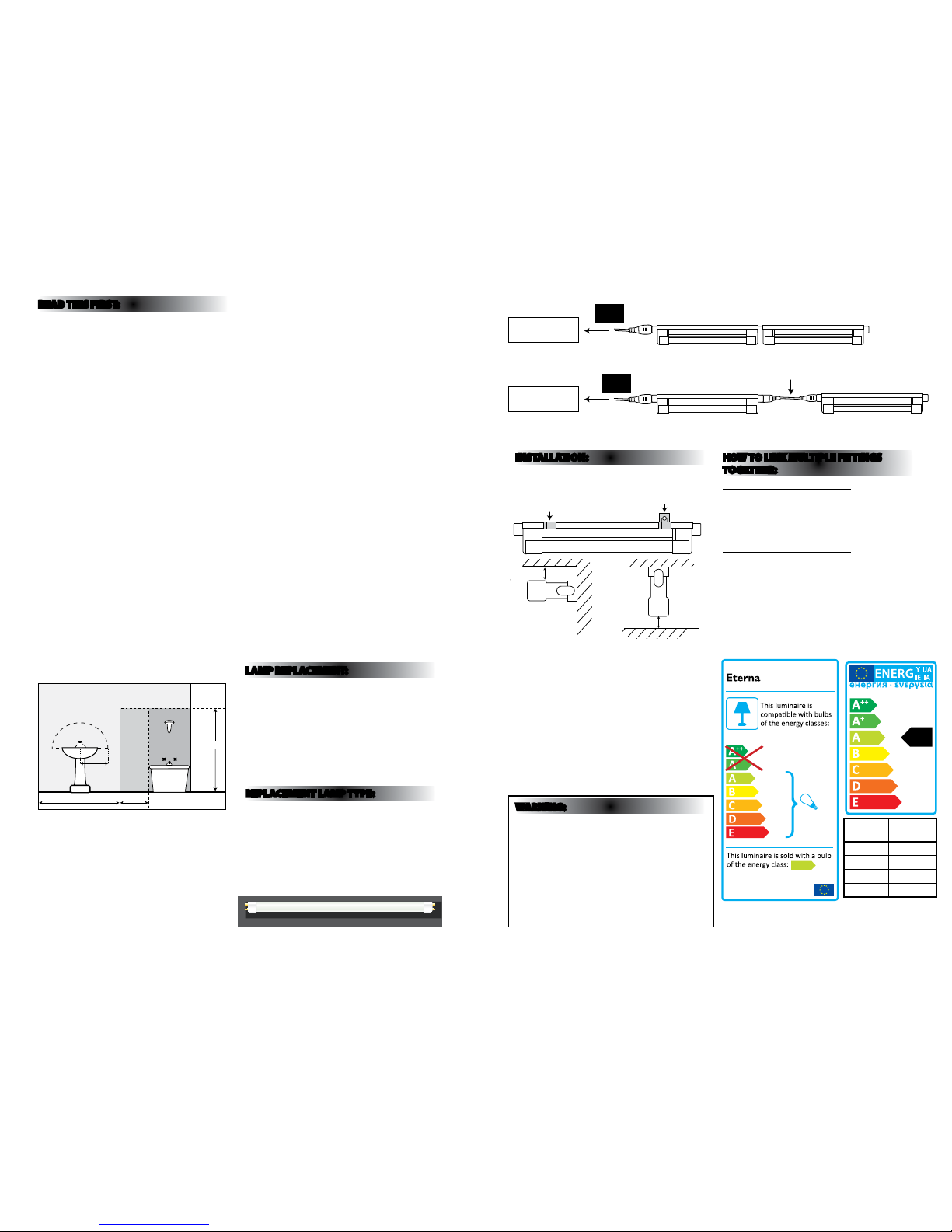
INSTALLATION:
01) When positioning the tting, make sure there is a
gap of at least 10mm be tween the lamp and any
adjacent surf ace. See below:
02) Select the t ype of brackets you ne ed to use and
mark o the xin g points. If xing to a she lf or under
a cupboard, check the screw size required and screw
into place. (See abo ve for clip positions).
03) If xing direc tly to the wall, drill hol es using a
suitable dril l bit to a depth of 30mm and inse rt wall
plugs.
04) Secure the s elected bracket s in place using the
screws supplied.
05) Attach the t ting to the clips.
06) Connect th e mains lead or link lead to th e socket on
your tting.
07) Restore the pow er supply and switch on.
WARNING:
The leads supp lied with your light tt ing and the
sockets incor porated in your ttin g are designed to give
protectio n against any possible ele ctrical hazard . The
mains lead is term inated in a socket marked NL S and
this lead shoul d be used to supply mains to you r tting
or chain of ttings. Under no circumstances should you
attempt to adap t the link lead to supply pow er to the
opposite end of y our tting as this will leave l ive pins
exposed at th e mains input end of the t ting. Altering
or adapting any of the leads, other than shortening the
mains supply le ad, will invalidate your guar antee and
could present a severe electrical shock hazard.
HOW TO LINK M ULTIPLE FITTINGS
TOGETHER:
OPTI ON 1 (REFE R TO FIG. 1 A BOVE)
The light tt ings can be butted tog ether to form a line
of up to a maximum of 6 ttings. Simply remove t he
connector c aps and push the ttings to gether. Use the
mains lead cabl e to connect the rst t ting and the
mains via a spur or ju nction box (not supplie d).
OPTI ON 2 (REFE R TO FIG. 2 A BOVE)
Connect link l eads between each t ting and once all
lights have been co nnected, connec t the mains lead to
the mains via a spur o r junction box (not suppl ied).
225cm
60cm240cm
60cm
radius
from tap
ZONE 1
ZONE 0
ZONE 2
ZONE 2
Bathroom Zones Diagram
10mm Gap
End View
End View
10mm Gap
“U Clip” “F Clip”
Mains via a spur
or junction box
Mains via a spur
or junction box
Eterna Link Leads Available:
NL1WH / NL50WH / NL25WH
Fig 2
Fig 1
874/2012
A
MODELNO.
TUS Range
Code
kwh /
1000h
N64/1 7.80
N64/3 12.67
N64/5 19.74
N64/7 24.31
A
Replace ment lamps avai lable: N64/1, N6 4/3, N64/5, N64/ 7
 Loading...