

Eterna TLS68EX Safety And Installation Instructions Manual
Safety Markings
Cleaning
Disconnect the power and clean the exterior
only of this switch with a moist (not wet) cloth.
Do not use any chemical or abrasive cleaners.
Load Specifi cation
Incandescent lighting loads - 16A maximum
Fluorescent lighting loads - 6A maximum
Compact lluorescent/low energy lighting loads
- 3A maximum
Low voltage lighting loads - 3A maximum
Note:
Note: a maximum of 6 fl uorescent light
fi ttings is recommended with total power factor
correction capacitance not exceeding 40µf.
Fans and ventilation equipment – 3A maximum
SON light fi ttings must be switched via a
contactor or other external relay. If you are
using this switch to control magnetic switch
start fl uorescent fi ttings and your light fi ttings
strike inconsistently, a power factor correction
capacitor may be required. If your light fi tting
fl ickers or fails to turn off correctly, this is most
likely to be due to incorrect or missing power
factor correction.
Check with the manufacturer of the light fi tting
and/or supplier of power factor correction
capacitors for the exact specifi cation required
for your installation. A minimum of 1µF for each
fi tting may be connected.
If you experience problems:
please return it to the place where you bought
it. You can call our Helpline for advice. The
any Eterna Lighting product but may not be able
to give specifi c instructions regarding individual
installations.
Tel: 01933 673 144
www.eterna-lighting.co.uk
TLS68EX
Time Delay Switch x 1
IP66 16(3)/240Vac
Installation
according to the conditions above.
2. Undo the large screws in each corner of the
front of the switch and lift off the lid.
3. Mark the positions of the fi xing holes at the
corners of a rectangle 62mm wide x 92mm
high.
4. Prepare the fi xing holes and insert wall
plugs if necessary.
5. Whether you are intending to use cable
glands or conduit to make your cable entry,
you will need to make hole(s) in the rear
half of the case to accept your chosen
fi tting.
6. Secure the rear half of the case to the wall
using suitable fi xings.
7. Make the electrical connections according
to the colour code on previous page.
8. Set the desired “on” time by combination
of DIP switches and the rotary control, see
9. Close the switch case and tighten the
screws. Take care not to over-tighten.
seconds for the switch to stabilise.
time.
adjustment, turn of the power at the mains
before opening the switch case. Remember
to wait 20s after restoring the power before
activating the switch again.
Note:
If you are using this switch to control
magnetic switch start fl uorescent fi ttings, a
power factor correction capacitor must be fi tted
with a minimum value of 1µF for each light
fi tting connected.
off correctly, this is most likely to be due to
incorrect or missing power factor correction.
Check with the manufacturer of the light fi tting
and/or supplier of power factor correction
capacitors for the exact specifi cation required
for your installation.
Trigger Function
The timer can be triggered by applying a live
connection to the “trigger” terminal. This can be
done using a momentary switch for example, in
lighting applications; or an unswitched link for
applications such as extractor fan over-run.
Multi-Point Switching
simply connect two or more units in parallel.
supply.
Read this fi rst
Check the pack and make sure you have all of
the parts listed on the front of this booklet. If
not, contact the outlet where you bought this
product.
This time delay switch must be installed by
a competent person in accordance with the
Building Regulations
making reference to the
current edition of the IEE Wiring Regulations
obtained from OPSI or viewed and downloaded
from www.communities.gov.uk following the
link for Building Regulations.
As the buyer, installer and/or user of this
product it is your own responsibility to ensure
that it is fi t for the purpose for which you have
intended it. Eterna Lighting cannot accept any
liability for loss, damage or premature failure
resulting from inappropriate use.
If in any doubt, consult a qualifi ed electrician.
This product is designed and constructed
according to the principles of the appropriate
service. Use of this switch in any other
environment, for example where prolonged
periods of use may be expected and/or higher
than normal ambient temperatures, may result
in a foreshortened working life.
Switch off the mains before commencing
installation and remove the appropriate circuit
fuse.
Do not overload the switch; check that the
total Wattage and start up surge current (if
any) of the connect load does not exceed the
maximum specifi ed.
Disconnect the switch from the electrical supply
before fl ash or high voltage testing.
Suitable for indoor and outdoor use.
are no obstructions hidden beneath the
mounting surface such as pipes or cables. If
your switch is part of the provision of a new
electrical supply, the supply must conform with
the requirements of the Building Regulations
making reference to the current edition of the
IEE Wiring Regulations (BS7671).
Make connections to the electrical supply in
accordance with the following code:
Live - Brown or Red
neutral connection.
When making connections, ensure that the
terminals are tightened securely and that
no strands of wire protrude. Check that
the terminals are tightened onto the bared
conductors and not onto any insulation.
This switch is double insulated; do not connect
any part to earth.
You are advised at every stage of your
installation to double-check any electrical
connections you have made. After you have
completed your installation there are electrical
tests that should be carried out: these tests are
specifi ed in the Wiring Regulations (BS7671)
referred to in the Building Regulations.
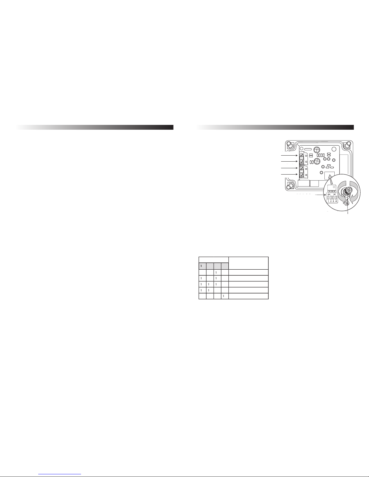
Switch Setting
Timer Function
2
3
4
000
2 seconds to 50 seconds
0050 seconds to 20 minutes
0
20 minutes to 70 minutes
0
0
70 minutes to 2 hours
Timer function disabled
DIP switch settings as follows: 1 = On, 0 = Off
DIP Switches
Rotary Control
Neutral In/Out
Live Out
Trigger
Trigger
Live In
 Loading...