

Page 1
Issue 2013
Model:
TLS1440
Electronic Time Delay Push Switch
These instructions are provided as a guideline to assist you.
PLEASE READ THESE INSTRUCTIONS BEFORE INSTALLATION
AND RETAIN FOR FUTURE REFERENCE
Pack contents:
1 x Fitting
2 x Fixing screws
2 x Blanking plug s
FOR PRODUCT ADVICE:
• T: 01933 673 144
• F: 01933 678 083
• E: sales@eterna-lighting.co.uk
Visit our website:
www.eterna-lighting.co.uk
INSTALLATION INSTRUCTIONS
A guide for qualied electricians
EVENTUALLY, YOU MAY WANT TO
REPLACE THIS PRODUCT:
Regulations require the recycling of Waste from
Electrical and Electronic Equipment (European
“WEEE Direc tive” eective August 20 05—UK
WEEE Regulation s eective 2nd January 20 07).
Environment Agenc y Registered Producer : WEE/
GA0248Q Z.
WHEN YOUR PR ODUCT COMES TO TH E END OF
ITS LIFE OR YO U CHOOSE TO REPLACE I T, PLEASE
RECYCLE IT W HERE FACILITIES E XIST DO NOT
DISPOSE WITH HOUSEHOLD WASTE.
CLEANING:
Clean this ttin g only with a soft dry clo th.
Do not use any chemic al or abrasive cleaners.
IF YOU EXPERIENCE PROBLEMS:
If you believe your p roduct is defective, p lease return
it to the place where yo u bought it. Our Technical
Team will gladly advise on any Eterna Lighting
product, bu t may not be able to give specic
instructions regarding individual installations.
For breakage inf ormation visit:
www.eterna-lighting.co.uk
Page 2
READ THIS FIRST:
Check the pack and m ake sure you have all of the
parts liste d on the front of this bookle t. If not,
contact the outlet where you bought this product.
As the buyer, install er and/or user of this product it
is your own responsi bility to ensure that this tt ing
is t for the purpo se for which you have intended
it. Eterna Lightin g cannot accept any liability fo r
loss, damage or premature failure resulting from
inappropriate use.
This product is designed and constructed according
to the principles o f the appropriate British Stan dard
and is intended fo r normal domestic ser vice.
This tting mus t be installed in accordance w ith the
Building Regulations.
Switch o the mains be fore commencing installati on
and remove the appropriate circuit fuse.
Do not overload th e switch, check that the total
wattage of th e switched load does not exce ed the
maximum liste d opposite.
Disconnect t he switch from the elect rical supply
before ash or hi gh voltage testing.
Suitable for indoor use only.
This produc t is only suitable for use in livi ng areas
(not for areas constan tly subject to moisture).
Before makin g xing hole(s), check that there are no
obstructi ons hidden beneath the mount ing surface
such as pipes or cab les.
Do not attach to su rfaces which are damp, fresh ly
painted or other wise electricall y conductive (e.g.
metallic sur faces).
If the location o f your new switch requires the
provision of a new el ectrical supply, the suppl y
must conform with the requirements of the Building
Regulations.
This switch is doub le insulated, do not connec t any
part to eart h.
You are advised at ever y stage of your installatio n to
double-check any electrical connections you have
made. After you h ave completed your installatio n
there are elec trical tests that should b e carried out:
these tests are sp ecied in the Wiring Reg ulations
(BS7671) referred to in the B uilding Regulations.
INSTALLATION:
01) Your new time lag switch can b e installed as a
direct repla cement for a normal one way wall
switch.
02) The sw itch body will t onto a standar d wall box
using the screws supplied.
03) Lever the m ounting screws out from the rea r of
the case using a smal l screwdriver
04) Conn ect the switch to the live supp ly wire at the
“LIVE IN” terminal.
05) Conne ct the live wire from your light tting or
other appliance to t he “LIVE OUT” terminal.
06) Do not connec t any neutral wires.
07) Do not connect a ny earth wires.
08) Do not connec t any ring live wires.
09) Adjus t the time delay control to minimum (12sec)
for testing.
10) Fit the swi tch to the wall box or pattress box an d
secure using the screws supplied.
11) Restore the power an d test the switch.
12) If any adjustme nts to the time delay are required ,
switch o the ele ctricity at the mains be fore
removing the sw itch to access the control.
OPERATION:
01) NORMA L OFF STATE: the red light glows inside
the switch but the p ower supply to the light
tting or appl iance is interrupted.
02) O N STATE : the red light inside the sw itch is
o and power is suppl ied to the light tting or
appliance.
Once the butto n has been pressed, the power
will be supplie d to the appliance for the time
period set on t he internal control (12 seconds
to 12 minutes approximately). The p ower will
be interrupted at t he end of the time cycle
regardless of any additional presses of the
button. Once t he time cycle has elapsed an d the
power interrupte d, the button can be press ed
again and the cyc le begun again.
03) NOTE: The time lag switch wil l switch loads of
any type up to a max imum of 6A. In a normal
incandescent li ghting or other resistive load , this
is approximately 140 0 Watts. You will need to
refer to manufac turers literature to deter mine the
start-up cur rent of inductive loads to de termine
the suitabilit y of this switch to your applicati on. If
using this switch to cont rol uorescent lighting,
the light tting s must have a high power factor, if
the power fac tor is low, a power factor correc tion
capacitor will n eed to be added.
04) Th is switch uses a transistor and no t a relay, this
enables faste r switching and prevents contac t
burnout to yield a longer and more reliable
operating life.
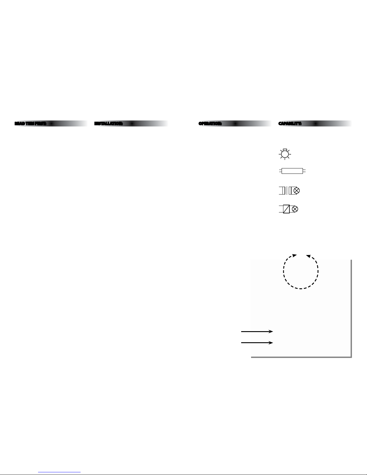
CAPABILITY:
Minimum load is 5 Wat ts.
This switch is suit able for switching the follo wing
loads:
Incandescent lighting
Fluorescent lighting
Low Voltage lighting w ith wire-wound transfo rmer
Low Voltage lighting w ith electronic transf ormer
LIVE OUT
Shorter - 12 secondsLonger - 12 minutes
LIVE IN
 Loading...