

Eterna SH3WH, AC6533 Installation Instructions Manual
Issue 2015
Model:
SH3WH / AC6533
3000W Screen Heater
These instructions are provided as a guideline to assist you.
PLEASE READ THESE INSTRUCTIONS BEFORE INSTALLATION
AND RETAIN FOR FUTURE REFERENCE
Pack contents:
1 x Fitting
1 x Adjustable mo unting bracket
1 x Fixing kit
FOR PRODUCT ADVICE:
• T: 01933 673 144
• F: 01933 678 083
• E: sales@eterna-lighting.co.uk
Visit our website:
www.eterna-lighting.co.uk
INSTALLATION INSTRUCTIONS
A guide for qualied electricians
EVENTUALLY, YOU MAY WANT TO
REPLACE THIS PRODUCT:
Regulations require the recycling of Waste from
Electrical and Electronic Equipment (European
“WEEE Direc tive” eective August 20 05—UK
WEEE Regulation s eective 2nd January 20 07).
Environment Agenc y Registered Producer : WEE/
GA0248Q Z.
WHEN YOUR PR ODUCT COMES TO TH E END OF
ITS LIFE OR YO U CHOOSE TO REPLACE I T, PLEA SE
RECYCLE IT W HERE FACILITIES E XIST DO NOT
DISPOSE WITH HOUSEHOLD WASTE.
CLEANING:
Disconnect t he power and clean the exte rior only of
this tting wit h a soft dry cloth.
Do not use any chemic al or abrasive cleaners.
IF YOU EXPERIENCE PROBLEMS:
If you believe your p roduct is defective, p lease return
it to the place where yo u bought it. Our Technical
Team will gladly advise on any Eterna Lighting
product, bu t may not be able to give specic
instructions regarding individual installations.
For breakage inf ormation visit:
www.eterna-lighting.co.uk
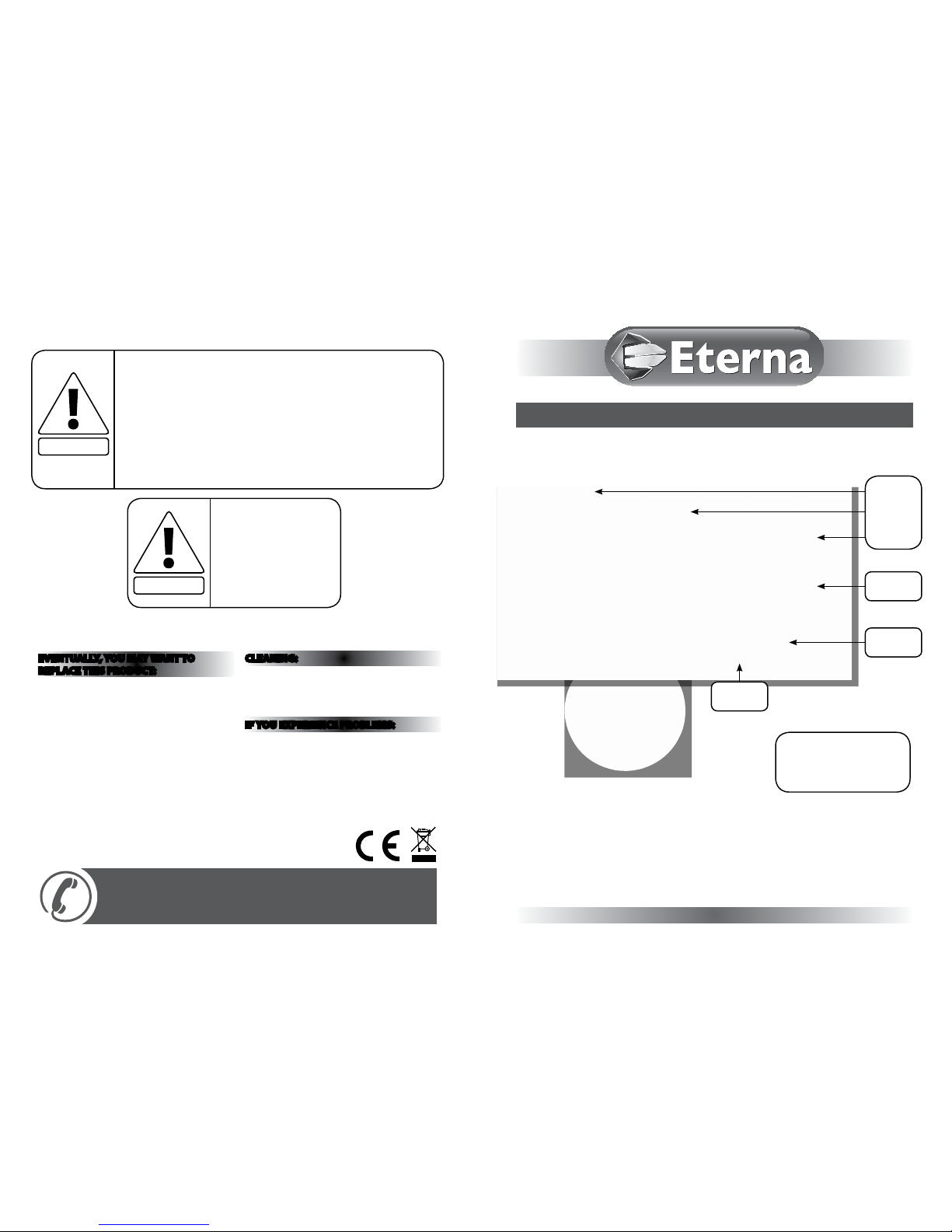
3 x screws
holding on
the front
panel
Front panel
Body
Switches
This heater is not equipped with a device to control the room temperature. Do not
use this heater in small rooms when they are occupied by persons not capable of
leaving the room on their own, unless constant supervision is provided.
Children of less than 3 years should be kept away from the heater unless
continuously supervised.
Children aged from 3 years and less than 8 years shall only switch on/o the
appliance provided that it has been placed or installed in its intended normal
operating position and they have been given supervision or instruction concerning
use of the appliance in a safe way and understand the hazards involved. Children
aged from 3 years and less than 8 years shall not plug in, regulate and clean the
appliance or perform user maintenance.
WARNING!
SOME PARTS OF THIS
PRODUCT CAN BECOME
VERY HOT AND CAUSE
BURNS. PARTICULAR
ATTENTION HAS TO BE
GIVEN WHERE CHILDREN
AND VULNERABLE
PEOPLE ARE PRESENT.
CAUTION!
READ THIS FIRST:
Check the pack and m ake sure you have all of the
parts liste d on the front of this bookle t. If not,
contact the outlet where you bought this product.
This produc t must be installed by a compet ent
person in accord ance with the current building a nd
IEE wiring regulations.
As the buyer, install er and/or user of this product it
is your own responsi bility to ensure that this tt ing
is t for the purpo se for which you have intended
it. Eterna Lightin g cannot accept any liability fo r
loss, damage or premature failure resulting from
inappropriate use.
This product is designed and constructed according
to the principles o f the appropriate British Stan dard
and is intended fo r normal domestic ser vice.
Suitable for indoor use only.
Suitable for x ing on a normally ammable sur face.
When choosing th e location for your new tt ing,
ensure that the xin gs will be anchored in a solid
surface e.g. con crete, brick or a joist—do not x
directly onto panelling, cladding, plasterboard etc.
WARNING: This product becomes hot!
This produc t is not intended to be used by childr en
and persons wi th sensory, physical and/or ment al
impairments th at would prevent them from using i t
saf ely.
Before makin g xing hole(s), check that there are no
obstructi ons hidden beneath the mount ing surface
such as pipes or cab les.
If the location o f your new tting requires th e
provision of a new el ectrical supply, the suppl y must
conform with the re quirements of the latest ed ition
of the IEE wiring re gulations.
Do not cover.
Switch o the mains be fore commencing installati on
and remove the appropriate circuit fuse.
Make connecti ons to the electrical supp ly in
accordance with the f ollowing code:
Live - Brown or Red
Neutral - Blue or B lack
Earth - Gree n and Yellow
If you are connec ting to the mains using a fused spu r,
a 13 Amp fuse should be tte d.
This produc t must be connected to Ear th.
Ensure that the heater c annot blow hot air directl y
onto any ammable sur face or any surface which
may be damaged or di scoloured by heat.
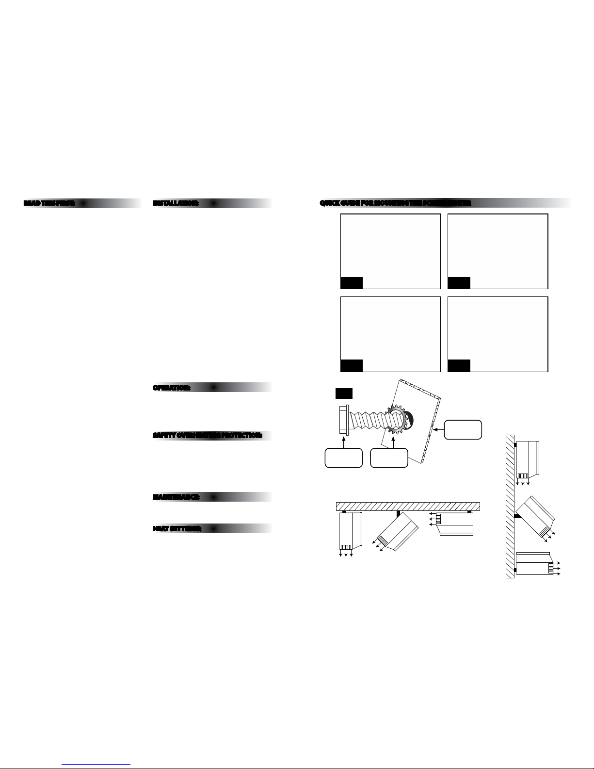
INSTALLATION:
01. Remove the three screws from t he front panel
and remove it. See f ront page.
02. Loosen, but do not r emove the retaining bolt
using a spanner and r emove the bracket. See Fig.
1 opposite.
03. Make xing holes in w all or ceiling using the wall
bracket as a template a nd secure bracket using
the xings suppl ied. If the xings supplie d are
not suitable for your installation, use appropriate
alternative xin gs. Note: the bracket must be
xed to a solid poi nt e.g. brick, concrete, stud o r
joist.
04. Hang the heate r on the bracket, ensure that the
bracket is locate d between the bolt and t he
serrated wash er and that the bolts are at the end
of the slots in the b racket.
05. Adjust the heater to th e required angle and
tighten the bolt s using a spanner. Take care not to
over-tighten.
06. Re-t th e front panel.
07. Connect mains cable (tted ) to the power supply
according to the wiri ng code above.
08. Restore th e power and switch on.
OPERATION:
The large switch i s a master switch, turning this
switch on and o will s tart and stop the fan and
heaters if sele cted.
The degree of h eat is controlled by switches I & II .
SAFETY OVERHEATING PROTECTION:
If the unit overheat s, thermal switches will cu t the
power and will res tore the power when the unit has
cooled down. H owever, if the unit overheats severely,
thermal fuses w ill isolate and then cut the power :
these fuses will n ot reset and cannot be repla ced by
the user. The unit shou ld be referred to a qualied ,
competent person for repair.
MAINTENANCE:
There are no user s erviceable part s inside. Refer
servicing o r repair to a qualied, compete nt person.
HEAT SETTINGS:
Master switch on ly: cold fan.
Master + switch I or I I: warm air (1500W).
Master + switche s I & II: hot air (3000W).
Retaining
bolt
Fig 1
Serated
washer
Mounting
point
Ceiling installation
Wall installation
QUICK GUIDE FOR MOUNTING THE SCREEN HEATER
STEP 1
STEP 3
STEP 2
STEP 4
 Loading...