

Page 1
Issue 2013
BS 14604:2005
KM539000
Model:
SDION
Mains Ionisation Smoke Detector with Battery Back-Up with “Hush” Feature
These instructions are provided as a guideline to assist you.
PLEASE READ THESE INSTRUCTIONS BEFORE INSTALLATION
AND RETAIN FOR FUTURE REFERENCE
Pack contents:
Ionisation Smo ke Detector x 1
Mounting Plate x 1
Mains Connect or x 1
9V Battery x 1
Fixing Kit x 1
FOR PRODUCT ADVICE:
• T: 01933 673 144
• F: 01933 678 083
• E: sales@eterna-lighting.co.uk
Visit our website:
www.eterna-lighting.co.uk
INSTALLATION INSTRUCTIONS
A guide for qualied electricians
SPECIFICATIONS:
Power Source: 220-240Vac~ 50-60Hz with 9V
battery back-up
Battery B ack-Up: 9Vdc Alkaline or Carbo n Zinc
battery :EVER READY PP3S
DURACELL MN1604 9V
Battery B ack-Up Life: In the event of a break in the
mains supply the b attery will
give detector operation for 1
year minimum.
Operating Cur rent: <20mA operation (in al arm),
15A in standby mode
Sensitivit y to Smoke: 0.61—1.92% per foot
obscuration
Operating Temper ature: 4°C - 38°C
Ambient Humid ity: 10% - 90%
Alarm Sound Leve l: 85 Decibels at 3 me tres
Interconnec t Facility: 40 smoke detector s.
Hush Facility: Mutes alarm for 10 minutes, i f
smoke density increases during
this time the alar m will be
re-triggered.
Approval: EN14604
Licence No: KM 539000
BATTERY REPLACEMENT:
1. Switch o the elec tricity at the mains.
2. Remove the lockin g tabs from the side of the a larm,
twist the ala rm anti clockwise and p ull away from the
base.
3. Remove the powe r connector.
4. Remove and rep lace the battery.
5. Replace the pow er connector.
6. Fit the alarm back onto t he base and twist clo ckwise,
ret the locking tabs.
7. Restore the power at the mai ns.
8. Check the alarm is fu nctioning by pushing t he test
button.
CLEANING:
Clean this smoke al arm only with a soft dr y cloth.
Periodicall y vacuum around the smoke al arm to dislodge
and remove dust p articles that may have gathe red.
Do not use any chemi cal or abrasive cleaner s.
EVENT UALLY, YOU MAY WANT TO REPLAC E
THIS PRODUCT:
Regulations require the recycling of Waste from
Electrical and Electronic Equipment (European “WEEE
Directive” eective August 2005—UK WEEE Regulations
eective 2nd January 2007). Environment Agency
Registered Producer: WEE/GA0248QZ.
WHEN YOUR PR ODUCT COMES TO T HE END OF ITS
LIFE OR YOU CH OOSE TO REPLACE IT, PLEA SE RECYCLE
IT WHERE FACI LITIES EXIS T DO NOT DISPOSE WI TH
HOUSEHOLD WASTE.
IF YOU EXPE RIENCE PROB LEMS:
If you believe you r product is defec tive, please return it
to the place wher e you bought it. Our Technical Team
will gladly adv ise on any Eterna Lighting pr oduct, but
may not be able to gi ve specic instruct ions regarding
individual installations.
PG 6 PG 1
Page 2
READ TH IS FIRST:
Check the pack an d make sure you have all of the par ts
listed on the fr ont of this booklet. I f not, contact the
outlet where you bought this product.
This tting mu st be installed in accor dance with the
Building Reg ulations. These may be ob tained from
HMSO or viewed and downloaded from www.odpm.gov.
uk following the link for Building Regulations.
Switch o the mains b efore commencing inst allation
and remove the appropriate circuit fuse.
Suitable for indoor use only.
This produc t is only suitable for use i n living areas (not
for areas const antly subject to moist ure).
The smoke alarm m ust not be exposed to dr ipping or
splashing.
Before maki ng xing hole(s), check that the re are no
obstructions hidden beneath the mounting surface such
as pipes or cabl es.
The chosen lo cation of your new alarm sh ould allow
for it to be secur ely mounted (e.g. to a ceiling jo ist) and
safely conne cted to a mains supply.
Do not attach t o surfaces which are damp, f reshly
painted or otherwise electrically conductive
(e.g. metallic surfaces).
If the locatio n of your new alarm require s the provision
of a new elect rical supply, the supply mus t conform to
the requirements of the Building Regulations.
This product is designed for permanent connection
to xed wiring: th is should be either a suit able circuit
(protecte d with a 5 or 6 Amp MCB or fuse) or a fuse d spur
(with a 3 Amp fuse) via a fu sed connection uni t.
Make connect ions to the electric al supply in accordance
with the follow ing code:
Live Brown or Red
Neutral Blue or Bla ck
Yellow Connect betwe en multiple alarms
This tting is d ouble insulated, DO NOT CON NECT ANY
PART TO EARTH.
Cable of at leas t 0.75mm
2
cross-sectional area must be
used to connec t to the supply and bet ween alarms.
You are advised at ever y stage of your insta llation to
double-check any electrical connections you have made.
After you have comp leted your installati on there are
electric al tests that should be c arried out: these tes ts are
specied in t he Wiring Regulations ( BS7671) referred to
in the Building Regulations.
LOCATING T HE SMOKE ALAR M:
This smoke alar m is a multi station ionisat ion alarm and
can be connec ted to other smoke alarms of t he same
make and typ e. This interconnect fe ature allows up
to 40 smoke detec tors to be connecte d together over
a distance of 150 metres m aximum, using the single
yellow wire thus al lowing all smoke detec tors to sound
when one is ac tivated. This smoke dete ctor cannot be
connected to a ny other device such as a re alar m panel.
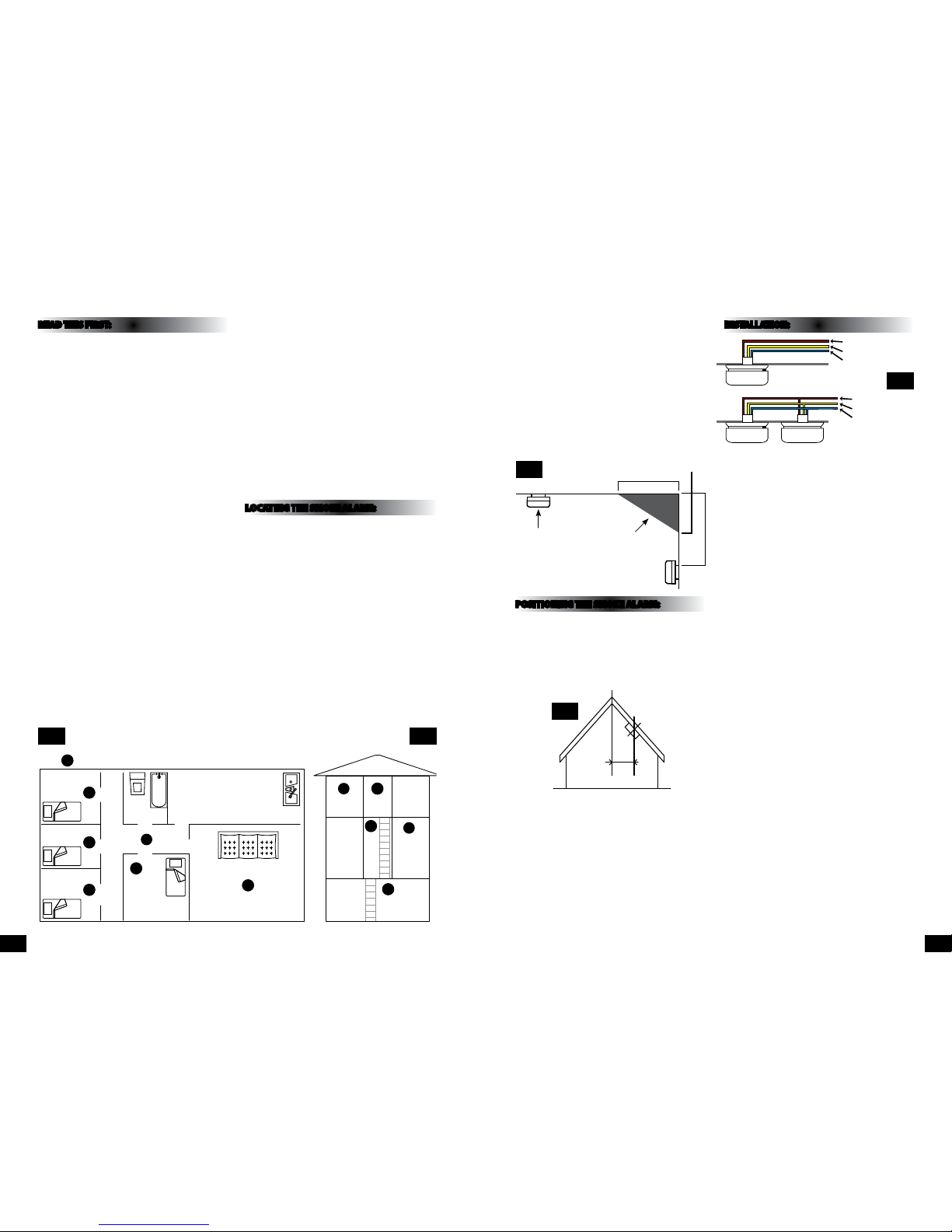
If your dwelling i s on a single storey, for minimum
protectio n you should t an alarm in the ha llway
between th e living areas (includin g kitchens) and the
sleeping are as. Place it as near to the livin g areas as
possible and e nsure that alarm is audible w hen the
bedrooms are occupied. See Fig.1 below.
If your dwelling is multi-storey, for minimum protection,
one alarm shou ld be tted at the bott om of the staircase
with furth er alarms tted on each up stairs landing.
This includes b asements but exclude s crawl spaces and
unnished at tics. See Fig. 2 below.
NOTE: For max imum protection, an al arm should be
tted in ever y room (except kitchen, b athroom and
garage).
DO NOT FIT A SMOK E ALARM IN THE KITCH EN OR
BATHROOM, as cooking fumes an d steam may trigger
the alarm.
DO NOT FIT A SMOK E ALARM IN A GARAGE as e xhaust
fumes could trigger the alarm.
The smoke alarm s hould be located at lea st 300mm
away from a light t ting. See Fig. 3 below.
POSITIONING THE SMOKE ALARM:
As smoke rises , it is advisable to mount th e alarm on a
ceiling in a centra l position. Avoid areas whe re there is
no air circulatio n e.g. corners of rooms an d keep away
from anythin g that might obstruct th e free ow of air.
If wall mountin g, do not mount tight into corne rs. On
sloping ceilin gs, mount 900mm fro m the apex measured
horizontally. See Fig. 4 below.
Areas to be avoided include the following:
• Locations where th e ambient temperature may f all
below 4°C or ris e above 40°C.
• Humid areas such as bathr ooms, kitchens, or sh ower
rooms where th e relative humidity may e xceed 90%.
• Fume lled environmen ts such as garages. Ex haust
gases may cause fa lse alarms.
• Adjacent to or directl y above hot objects su ch as
radiators or wa ll vents that can aect t he direction of
air currents.
• In very dusty or dirty environments such as workshops.
INSTALLATION:
01. Remove the base plate fr om the alarm.
02. Using the mounting plate as a temp late mark the
position of the xing holes.
03. Place base plate over xi ng holes and secure usin g
the wall plugs an d screw supplied, (if wall p lugs and
screws supplie d are not suitable for you r application
use suitable alternatives).
04. Connect the p ower connector to the inco ming mains
supply observing the wiring colour code opposite. If
multiple smoke a larms are not to be interconne cted,
isolate the yell ow wire in a separate termin al block
and wrap well wi th insulation tape.
05. When smoke alarms are t o be interconnected,
connect all of t he yellow wires togethe r.
06. If the smoke alarm s are to be locked into positi on,
remove the two t amper-proof tabs fro m the
mounting plate a nd retain for use later.
07. Insert the 9V b attery into the smoke a larm noting
the polarit y of the connections . Ensure the metal tab
is fully depres sed when the batter y has been tted.
Note: For safet y of the end user the smoke a larm
cannot be t ted without its batte ry.
08. Before assemb ly to the base plate test the co rrect
operation of the smoke detector (operating from the
battery o nly) by pressing the test but ton on the front
of the detect or. The unit should emit a loud p ulsing
alarm.
09. Conn ect the power connec tor into the socket on the
rear of the smoke de tector. Note: This is a pola rized
connector and can only be plugged in one way.
10. Asse mble the detector onto t he base plate by
aligning the t wo projections on the b ase plate with
the two keyhol e slots in the detecto r. Lock in position
by turning clockwise.
11. Insert the tw o tamper-proof tabs in th e slots
provided in th e side of the unit. Once t ted the
detector ca n only be removed from th e base plate
by rst removin g these tabs, gently pr ising them out
with a screw drive r.
12. Replace the circuit f use and restore the power.
13. Test the correc t operation of the smo ke detector by
pressing the tes t button on the front of th e detector,
the alarm shoul d emit a loud pulsating al arm.
Fig 2
Fig 4
Fig 5
Fig 1
Bedroom
Bedroom
Hall
Bedroom
Bedroom
Living Room
Kitchen
KEY: Maximum Protection
Bathroom
Bedroom
Kitchen
Basement
Landing Bathroom
Living
Room
Hall
Fig 3
Ceiling
1 metre
Best in
centre
of
room
Dead air space
- do not mount
in this area
15cm mim
30cm max
900mm
Live (Brown)
Interconnect (Yellow)
Neutral (Blue)
Live (Brown)
Interconnect (Yellow)
Neutral (Blue)
PG 2 PG 3
Page 3

OPERATION:
Once your smoke al arm has been installe d a small GREEN
indicator light ( LED) should be visible thro ugh the
detector gr ill indicating that the AC supp ly is healthy. A
RED indicator li ght (LED) should also ash appr oximately
once a minute to indi cate that the battery i s healthy.
When smoke is det ected, the unit will em it a loud
pulsating alar m and a RED indicator light (LE D) will ash
quickly until the air is clear.
The “HUSH” fea ture can mute the detec tor if it has been
inadvertently triggered by holding down the test button
for a few second s. The smoke alarm will be m uted for
10 minutes and then res et into normal mode af ter this
period.
NOTE: if the smoke density increases during this time
the smoke alarm w ill be triggered again .
TESTIN G YOUR SMOKE ALA RM:
After insta llation and after reo ccupation of the dwellin g
following a vac ation etc; check all alar ms for correct
operation.
It is recommend ed that you test your smoke al arm once
a week to ensure the d etector is working co rrectly.
Push and hold the te st button for approxi mately 3
seconds. A loud pulsating alarm should sound and a RED
ashing indic ator light (LED) can be seen to ind icate that
the unit is functioning correctly.
NOTE: For multiple inter connected smoke alar ms,
test each alarm in t urn checking also that t he alarm is
triggered on all other smoke alarms.
MAINTAINING YOUR SMOKE ALARM:
If the smoke dete ctor emits a short “ beep” once a minute
the batter y is at the end of its life and sh ould be replaced
immediately. Thi s low voltage warning wil l be given for
at least 7 days.
WARNING: The use of b atteries other than
those recomme nded on the back of the smo ke alarm
may be detrimental to its operation.
Clean your smoke al arm regularly to prevent d ust build
up. This can be do ne using a vacuum cleaner w ith the
brush attachment. Clean gently around the front grille
section and the sides.
IMPORTANT:
If there is any ques tion as to the cause of an alar m it
should be assum ed that the alarm is due to an ac tual re
and the dwelling s hould be evacuated imm ediately.
IN THE EV ENT OF FIRE:
1. Leave the bu ilding as quickly as poss ible. Check room
doors for hea t or smoke. Do not open a hot do or. Use
an alternative es cape route. Crawl along t he oor, if
possible, bre athe through a wet cloth or ho ld your
breath. Do not s top to collect anythin g.
2. Me et at a pre-arrange d meeting place outsi de the
dwelling and che ck everybody is the re.
3. Cal l the Fire Brigade immedi ately from outside
the building. The brigade should be summoned
regardless of t he size of the re and regardl ess of
whether ther e is a facility for transm ission of alarms to
a remote manned centre.
4. Do n ot go back inside a burning b uilding, wait for the
Fire Brigade to ar rive.
IMPORTANT SAFEGUARDS:
Installatio n of your smoke alarm is only on e step in your
safety pla n. Other importa nt steps should be taken to
further improve your safety:-
• Ins tall this smoke alarm prop erly, following this
instruction leaet.
• Test your smoke alarm we ekly.
• Replace the battery immediately once depleted.
• Do not smoke in be d.
• Keep matches and l ighters away from children .
• Store ammable materials in a prop er manner and
never use them ne ar naked ames or spark s.
• Maintain emergenc y equipment such as re
extinguis hers, escape ladde rs etc. and ensure all
occupants kn ow how to use them correct ly.
• Plan an e scape route(s) from your bui lding in advance
and ensure all occu pants are aware of them. Re -enforce
this awareness periodically throughout the year.
• Make su re that escape routes rem ain free of any
obstructions.
THIS PRODUCT IS SEALED AND
CANNOT BE REPAIRED. IF THE
UNIT IS TAMPERED WITH IT WILL
INVALIDATE THE GUARANTEE.
IF THE UNIT IS FAULTY, PLEASE
RETURN IT TO YOUR ORIGINAL
SUPPLIER WITH YOUR PROOF OF
PURCHASE.
COMMON C AUSES AND AVOIDIN G FALSE
ALARMS:
The Smoke Alarm m ay be triggered by steam,
condensation, normal smoke or fumes. Small insects
getting into th e smoke alarm chamber may c ause
intermitten t alarms. Keep away from the se sources to
avoid nuisance ala rms. (See “Areas to be avoided” in t he
“Positioning t he smoke alarm” sectio n on page 3.)
This Smoke Alarm h as a built-in Hush or Silence fe ature
incorporated into the Test button.
If cooking or other non-hazardous sources cause
the unwanted alar m, it can be temporaril y silenced
by depressing the test button and holding for
approximatel y 3 seconds. The alarm wi ll enter a dormant
period for 10 minut es. The red LED will ash ever y 10
seconds to indi cate the sensitivity i s reduced. At the end
of the hush peri od the alarm will give two s hort beeps,
the alarm will then reset to normal sensitivity.
NOTE: If the smoke de nsity increases duri ng this period
(i.e. from a re) the un it will go into alarm mode.
On interconnected alarms, pressing the test/hush
button on the s ensing smoke unit will mute a ll alarms.
However, pressing the h ush button on any other uni t will
NOT cancel the ala rm.
Action in the eve nt of a false alarm.
If there is a fals e alarm, simply press the te st / hush
button on the cov er to mute the unit for 10 minutes.
Check the hous e carefully in case ther e is a small re
smouldering somewhere.
Check whether there are some sources of smoke or
fumes. You should g et your family into a safe pla ce
before your investigation.
If there are fre quent nuisance/ false a larms it may be
necessar y to re-locate the dev ice. If for some reasons
the alarm continu es to give false alarm, the un its can
be silenced by di sconnecting the main s power and
removing the un it. If cleaning the alarm d oes not correct
the problem it c an be returned to the pla ce where you
bought it.
YOUR SMOK E ALARM GUARAN TEE:
This smoke dete ctor is guaranteed to be f ree from
defects in materials and workmanship under normal
use and serv ice for a period of ve year s from the date
of purchase. Th e company will not be obliga ted to
repair or repl ace parts which are fou nd to be in need
of replacemen t or repair because of mis use, damage or
alterations ma de after the date of purch ase.
In case of a claim un der the terms of the guarante e,
please retur n the detector to the pla ce where you
bought it compl ete with all parts and p roof of purchase.
The liabilit y of the company arising fro m the sale of this
smoke detec tor shall not in any case excee d the cost
of the replacem ent of this smoke detecto r and in no
case shall the com pany be liable for the conse quential
loss or damages r esulting from the failur e of the smoke
detector.
ETERNA LIGH TING LIMITED SHALL HAVE NO LIAB ILITY
FOR ANY PERSONAL IN JURY OR DAMAGE TO PROPERTY,
OR ANY SPECIAL INCIDE NTAL, CONTINGENT OR
CONSEQUENTIAL DAMAG E OF ANY KIND RESULTING
FROM A FIRE. THE E XCLUSIVE REMEDY FOR BREACH OF
THE LIMITED WARR ANTY CONTAINED HEREIN IS THE
REPAIR OR REPLACEMENT O F THE DEFECTIVE PRODU CT
AT ETERNA LIGHTIN G LIMITED. OPTION. T HE LIABILITY
OF ETERNA LIG HTING SHALL IN NO CASE E XCEED THE
PURCHASE PRICE OF T HE DETECTOR UNDER AN Y OTHER
REMEDY PRESCRIBE D BY LAW. YOUR SMOKE ALARM
IS NOT A SUBSTITU TE FOR PROPERTY, DISABILIT Y, LIFE
OR OTHER INSURA NCE OF ANY KIND. APPROPRIATE
COVERAGE IS YOUR RESPO NSIBILITY. CONSULT YOUR
INSURANCE AGENT.
This does not a ect your statutor y rights.
This alarm is onl y suitable for single occ upancy private
dwellings and not intended for multi occupancy private
dwellings or commercial or industrial premises.
PG 4 PG 5
 Loading...