

Eterna SA360PIR Safety And Installation Instructions Manual
TECHNICAL INFORMATION
• Switching Load: Maximum 8A 1600W Resistive or 500W Fluorescent
• Supply Voltage: 230V 50 Hz
• Time Control: From approx 10 seconds to approx 15 minutes ± 2
• LUX Control: Daylight & Night adjustable.
• Detection Range: 360° Up to 5 metre radius mounted at 3 metres.
• Mounting Height: 3 metre maximum.
• Protection: Class I I
CLEANING:
Clean this PIR unit only with a soft dry cloth.
Do not use any chemical or abrasive cleaners.
EVENTUALLY, YOU MAY WANT TO REPLACE THIS FITTING:
When your PIR unit comes to the end of its life or you choose to update or upgrade it by replacing it,
please do not dispose of it with your normal household waste, please recycle where facilities exist. When
you need to dispose of this fitting, check with your retailer or local authority for suitable options. New
regulations require the recycling of Waste from Electrical and Electronic Equipment (European “WEEE
Directive” effective August 2005—UK WEEE Regulations effective 2nd January 2007). Environment Agency
Registered Producer: WEE/GA0248QZ
IF YOU EXPERIENCE PROBLEMS:
If your PIR unit is defective or develops a fault, please return it to the place where you bought it. You
can call our Helpline for advice. The Helpline will gladly give advice on any aspect of any Eterna Lighting
product but may not be able to give specific instructions regarding individual installations.
If in doubt, consult a qualified electrician.
SAFETY AND INSTALLATION INSTRUCTIONS
110804-SM
T: 01933 673 144 • F: 01933 678 083 • E: sales@eterna-lighting.co.uk
For answers to frequently asked questions (FAQs)
and other information visit our website:
www.eterna-lighting.co.uk
HELPLINE:
Pack contents:
SA360PIR x 1
Screws x 2
Model:
Wall Plugs x 2
SA360PIR
Stand Alone Internal 360° PIR
Sensor
These instructions are provided as a guideline to assist you.
PLEASE READ THESE INSTRUCTIONS BEFORE INSTALLING YOUR NEW ALARM
PLEASE RETAIN FOR FUTURE REFERENCE
360
o
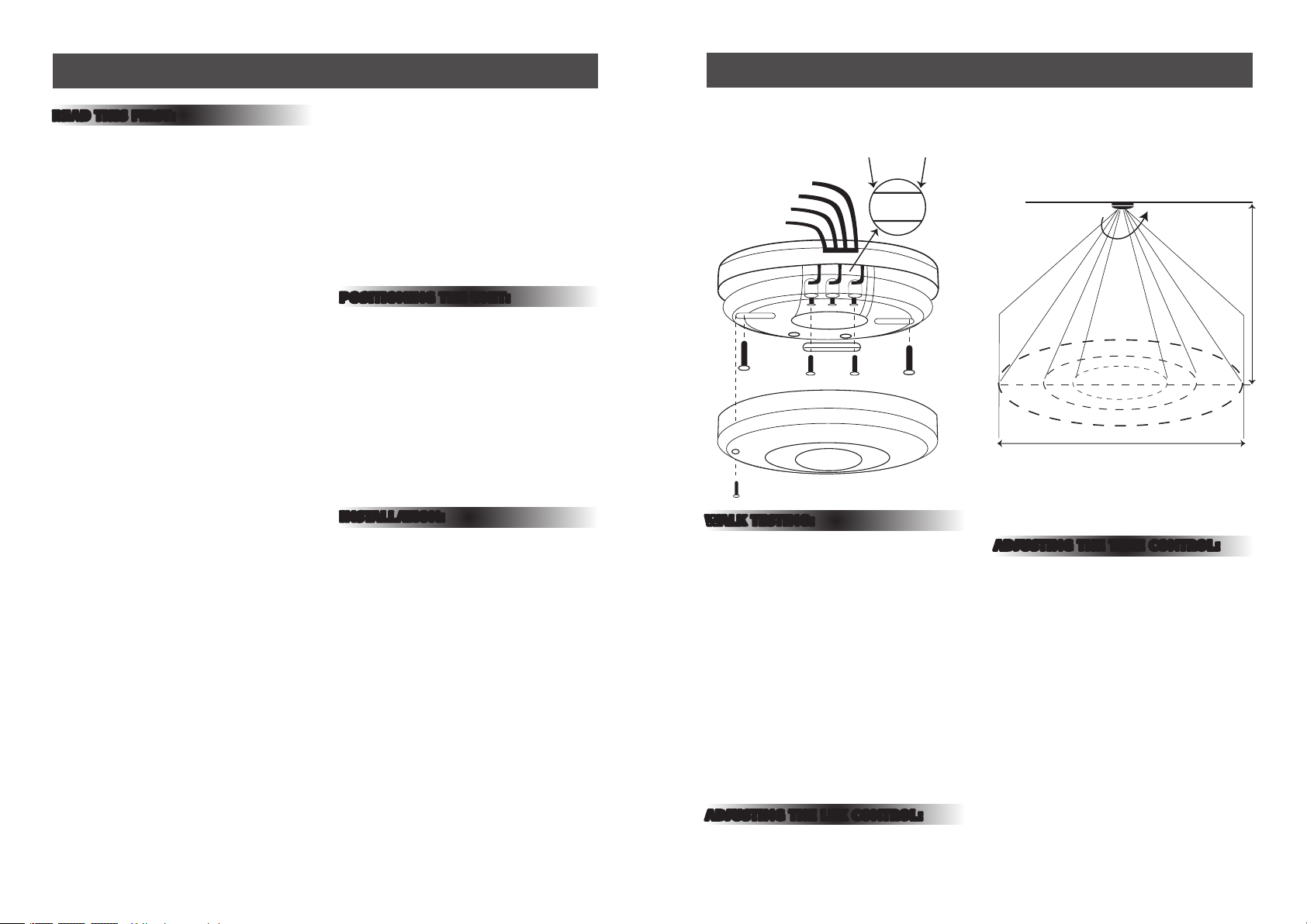
Ceiling
Brown (Load)
L in L out
Blue (Load)
Blue (Main Power)
Brown (Main Power)
3m
Max 5m Radius
L N L
General Information and Safety Instructions:
Installation:
READ THIS FIRST:
Check the pack and make sure you have all of
the parts listed on the front of this booklet. If
not, contact the outlet where you bought this
product.
This sensor must be installed by a
competent person in accordance with the
current building and IEE wiring regulations.
As the buyer, installer and/or user of this
product it is your own responsibility to ensure
that this fitting is fit for the purpose for
which you have intended it. Eterna Lighting
cannot accept any liability for loss, damage or
premature failure resulting from inappropriate
use.
If in any doubt, consult a qualified electrician.
This product is designed and constructed
according to the principles of the appropriate
British Standard and is intended for normal
domestic service. Using this fitting in any
other environments, for example where there
is prolonged periods of use or higher than
normal ambient temperatures, may result in a
shortened working life.
Switch off the mains before commencing
installation and remove the appropriate circuit
fuse or lock off MCB.
Do not connect to a circuit which also has
inductive loads connected; switching of
inductive loads will generate spikes which may
damage electronic components within your PIR.
This unit is suitable for indoor use only.
This product is suitable for use in living areas.
(Not for area constantly subjected to moisture)
This product is suitable for installation on
surfaces with normal flammability e.g. wood,
plasterboard and masonry.
Before making fixing hole(s), check that there
are no obstructions hidden beneath the
mounting surface such as pipes or cables.
Do not attach to surfaces which are damp,
freshly painted or otherwise electrically
conductive (e.g. metallic surfaces).
When making connections ensure that the
terminals are tightened securely and that
no strands of wire protrude. Check that
the terminals are tightened onto the bared
conductors and not onto any insulation.
This fitting is double insulated; do not connect
any part to earth.
IMPORTANT— you are advised at every stage of
your installation to double-check any electrical
connections you have made. After you have
completed your installation there are electrical
tests that should be carried out, these tests are
specified in the current IEE wiring and building
regulations. If in doubt, consult a qualified
electrician.
POSITIONING THE UNIT:
When selecting the mounting position, take into
account the following points:
1) The sensor is designed for optimum
performance when mounted on ceiling.
(see fig. 2)
2) Avoid pointing or positioning close to heat
sources or heat extraction units, which may
cause false triggering.
3) Avoid pointing at bright lights as unit will not
function when you set Lux control level to dark
(Ç).
INSTALLATION:
Switch off power and isolate circuit by
removing the appropriate fuse.
1) Remove the small screw located in the lens
cover.
2) Using the PIR base as a template mark the
fixing positions on the mounting surface.
3) Pierce the membrane of the grommet, pass
mains and load cable through the cable entry.
4) Connect the incoming LIVE to the terminal
marked (L in) and connect the incoming
NEUTRAL to the terminal marked N. (see fig.1)
5) Connect the load LIVE to the terminal Marked
(L out) and connect the load NEUTRAL to the
terminal marked N. (see fig.1)
6) Fix PIR to prepared mounting surface with
screws and wall plugs provided.
7) Restrain cables with cable clamp and fit cover.
8) Restore power.
9) Conduct walk test using the instruction set out
opposite:
Installation Diagram (Fig. 1) Detection Area (Fig. 2)
WALK TESTING:
Note: When power is switched on to the PIR
unit, the detector will enter into a “WARM-UP”
period for approximately 30 seconds and then
automatically change into “AUTO MODE”. While in
the AUTO MODE, you can then carry out a walktest, as per instructions below.
1) While in “AUTO MODE” you can commence the
walk test. The LUX dial should be set to the day
position (toward the Ô symbol) and the time
control to the minimum position (toward the
— symbol).
2) Walk slowly during the walk testing in order to
gain the desired detection area.
3) When the walk test is complete set the LUX
level & TIME on adjustment controls to the
desired settings.
photocell to stabilise at the desired level.
ADJUSTING THE TIME CONTROL:
The length of time that the switch remains on can
be adjusted from approximately (10±5) seconds
to approximately 15±2) Minutes. This is adjusted
by rotating the time (Time + /-) gauge. Once the
load has been triggered by the PIR detector, any
subsequent movement will start the timed period
from the beginning.
ADJUSTING THE LUX CONTROL:
The LUX control has a built in photocell which
detects daylight and darkness. Rotate the LUX
control (Lux Ô/Ç) to set to the desired level of
daylight. Allow approximately 5 seconds for the
 Loading...