

Page 1
Model:
RDT10A
Photoelectric Switch with Timer
These instructions are provided as a guideline to assist you.
PLEASE READ THESE INSTRUCTIONS BEFORE INSTALLATION
AND RETAIN FOR FUTURE REFERENCE
EVENTUALLY, YOU MAY WANT TO
REPLACE THIS PRODUCT:
Regulations requi re the recycling of Waste from
Electrical and Electronic Equipment (European
“WEEE Direc tive” eective August 2005— UK
WEEE Regulations ee ctive 2nd January 2007).
Environment Agency Registered Producer: WEE/
GA0248QZ.
WHEN YOUR PRO DUCT COMES TO THE EN D OF
ITS LIFE OR YOU C HOOSE TO REPLACE IT, PLEASE
RECYCLE IT W HERE FACILITIES EXIS T DO NOT
DISPOSE WITH HOUSEHOLD WASTE.
TECHNICAL INFORMATION:
Supply Voltage: 230V AC
Resistive load: 10A
Inductive load: 3A
Wattage: Max. 250W LED
(no more than 10 lights)
Time on adjustable: Between 1-8 hours
or dusk to dawn
Lux adjustable: Between 5-300 lux
ENERGY EFFICIENCY:
This product is suitable for use with low energy
bulbs. Please use a low energy lamp wherever
possible.
This product has adjustable settings. Adjust the
timer so that the light is only on when required.
CLEANING:
Disconnect the p ower and clean the exterior onl y
of this tting with a m oist (not wet) cloth.
Do not use any chemical o r abrasive cleaners.
IF YOU EXPERIENCE PROBLEMS:
If you believe your pro duct is defective, please
return it to the place wh ere you bought it.
Our Technical Team will gladly advise o n any
Eterna Lighting prod uct, but may not be able to
give specic instructions regarding individual
installations.
Pack contents:
1 x Fitting
1 x Fixing kit
Email: sales@eterna-lighting.co.uk / technical@eterna-lighting.co.uk
Visit our website: www.eterna-lighting.co.uk
Made in ChinaIssue 0217
INSTALLATION INSTRUCTIONS
A guide for qualied electricians
Page 2
READ THIS FIRST:
Check the pack and make sure you have all of
the parts listed on the front of this booklet. If
not, contact the outlet where you bought this
product.
This photoelectric timer must be installed by
a competent person in accordance with the
Building Regulations making reference to the
current edition of the IEE Wiring Regulations
(BS7671).
As the buyer, installer and/or user of this product
it is your own responsibility to ensure that this
photoelectric timer is t for the purpose for
which you have intended it. Eterna Lighting
cannot accept any liability for loss, damage or
premature failure resulting from inappropriate
use.
Switch o the mains before commencing
installation and remove the appropriate circuit
fuse.
When working at heights, please use a suitable
platform.
Do not overload the timer; check that the total
Wattage of all ttings does not exceed the
maximum marked on the timer.
Disconnect the timer from the electrical supply
before ash or high voltage testing.
Suitable for outdoor use.
Before making xing hole(s), check that there are
no obstructions hidden beneath the mounting
surface such as pipes or cables.
Select an open area for installation where
articial light (especially the controlled load) will
not enter the window on the front of the unit.
The chosen location of your new timer should
allow for the product to be securely and safely
connected to the mains supply (lighting circuit).
If the location of your new timer requires the
provision of a new electrical supply, the supply
must conform with the requirements of the
Building Regulations making reference to the
current edition of the IEE Wiring Regulations
(BS7671).
This product is designed for permanent
connection to xed wiring: this should be either
a suitable lighting circuit (protected with a 5
or 6 Amp MCB or fuse) or a fused spur (with a
3 Amp fuse) via a fused connection unit. We
recommend that the supply incorporates a
switch for ease of operation.
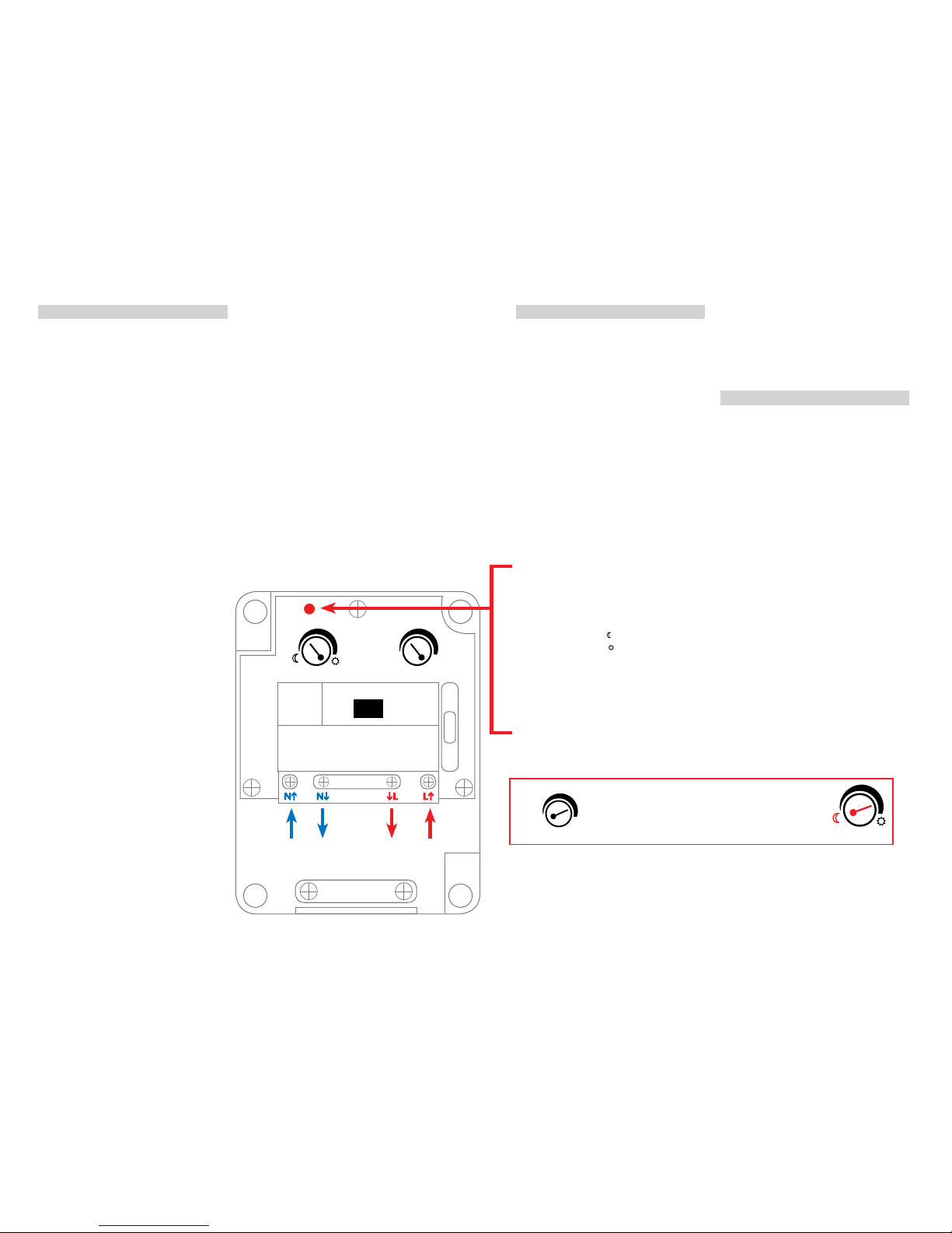
Make connections to the electrical supply
in accordance with the following code and
diagram:
Live - Brown or Red
Neutral - Blue or Black
When making connections, ensure that the
terminals are tightened securely and that
no strands of wire protrude. Check that
the terminals are tightened onto the bared
conductors and not onto any insulation.
This timer is double insulated; do not connect
any part to earth.
You are advised at every stage of your
installation to double-check any electrical
connections you have made. After you have
completed your installation there are electrical
tests that should be carried out: these tests are
specied in the Wiring Regulations (BS7671)
referred to in the Building Regulations.
INSTALLATION:
01. Choose the location for your timer according to
the conditions above.
02. Undo the screws in each corner of the front of
the timer and lift o the lid.
03. Mark the positions of the xing holes at 2 of
the corners
04. Prepare the xing holes and insert wall plugs if
necessary.
05. Secure the rear half of the case to the wall
using suitable xings.
06. Make the electrical connections to the colour
code:
Live - Brown or Red, Neutral - Blue or
Black.
Also refer to Fig. 1 oppsosite.
07. Install light ttings and make connections
according to the manufacturers instructions.
08. Restore the mains power.
09. When the timer is initially energised the
LIGHT FITTING & RED INDICATOR WILL
FLASH THREE TIMES
.+.+.
10. Adjust the lux control screw to the desired
setting.
Minimum setting ( ) approx 5 lux
Maximum setting ( ) approx 300 lux
11. Adjust the timer control screw to desired
setting between 1 and 8 hours or dusk to dawn
setting.
THE RED INDICATOR WILL FLASH ONCE IF
THE TIMER IS SET FOR 1 HOUR, TWICE FOR 2
HOURS AND SO ON.
IN THE CASE OF THE DUSK TO DAWN SETTING
THE RED INDICATOR WILL FLASH RAPIDLY TEN
TIMES.
12. Check gaskets are correctly positioned before
closing lid.
13. Replace cover and tighten screws being careful
not to over tighten.
When the set lux level has been reached the LED
indicator will illuminate indicating that the load
will be switched on in approximately 60 seconds.
The light tting will be switched on and will
remain on for the set time period or until dawn if
the “dusk to dawn” setting has been selected.
PLEASE NOTE:
When the load is switched on and the intensity
of another light source exceeds the o lux value
the load will be switched o after approximately
60 seconds and the timer will stop counting back
to the set switch o time period. If the other light
source is eliminated within approx 10 minutes the
load will be switched on again and the timer will
restart counting back to the set switch o time
period.
During the timed period the electronic timer will
be reset (i.e will return to the start of the set time
period) if power is interrupted for more than 2
seconds.
TIMER
DUSK
TO DAW N
1
2
4
6
8
LUX
LUX
TIMER
DUSK
TO DAW N
1
2
4
6
8
INDICATOR
BROWN
OR RED
LOAD
N = NEUTRAL
L = LIVE
IN LOAD
240V
BLUE OR
BLACK
IN INOUT OUT
Fig 1
NOTE:
When the dusk to dawn setting is selected on the timer
dial, the moon setting needs to selected on the lux dial.
 Loading...