

Page 1
Model:
RDL12 / RDL18
Recessed LED Downlight
These instructions are provided as a guideline to assist you.
PLEASE READ THESE INSTRUCTIONS BEFORE INSTALLATION
AND RETAIN FOR FUTURE REFERENCE
Pack contents:
1 x Fitting
1 x Driver
1 x 250mm cable
INSTALLATION INSTRUCTIONS
A guide for qualied electricians
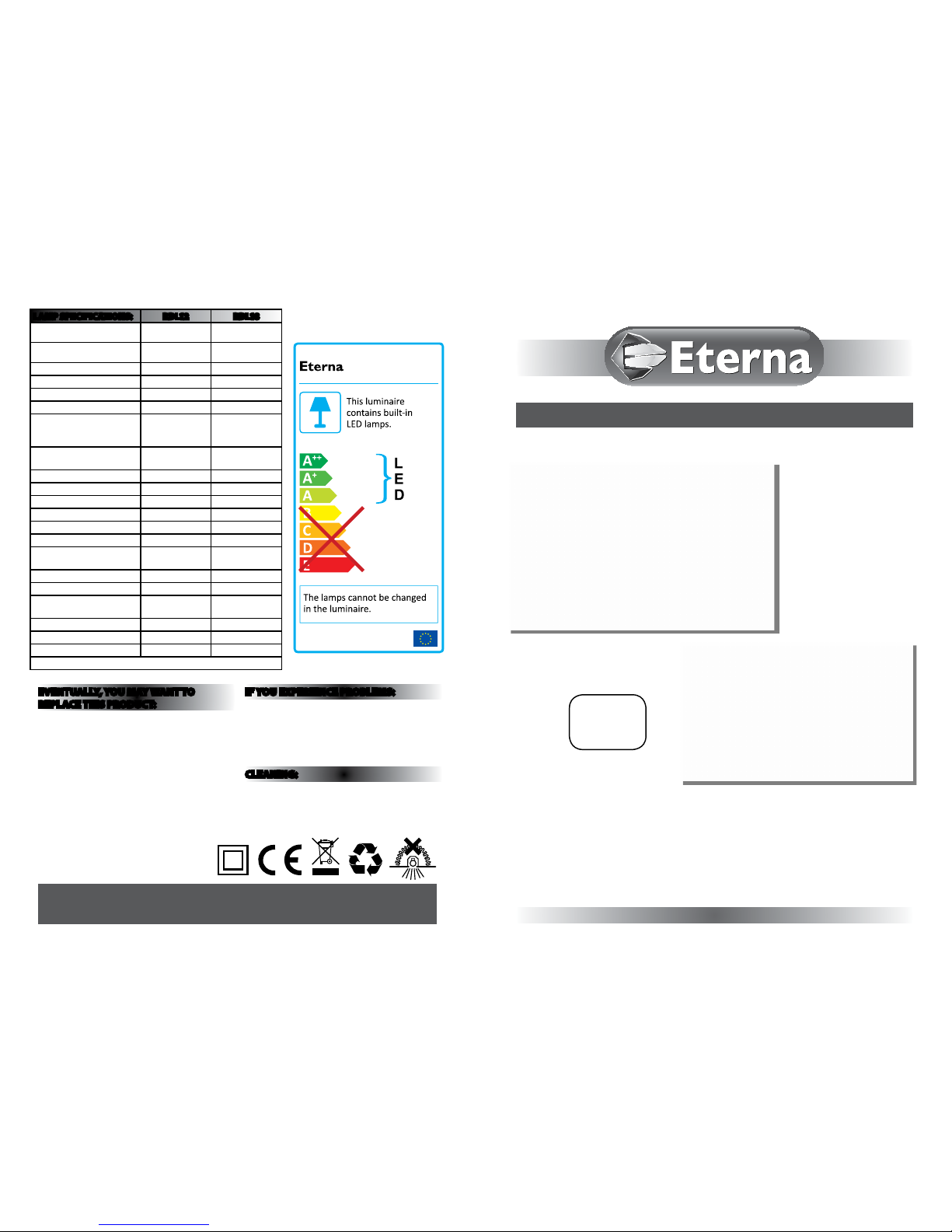
874/2012
MODELNO.
RDL Range
EVENTUALLY, YOU MAY WANT TO
REPLACE THIS PRODUCT:
Regulations require the recycling of Waste from
Electrical and Electronic Equipment (European
“WEEE Direc tive” eective August 20 05—UK
WEEE Regulation s eective 2nd January 20 07).
Environment Agenc y Registered Producer : WEE/
GA0248Q Z.
WHEN YOUR PR ODUCT COMES TO TH E END OF
ITS LIFE OR YO U CHOOSE TO REPLACE I T, PLEA SE
RECYCLE IT W HERE FACILITIES E XIST DO NOT
DISPOSE WITH HOUSEHOLD WASTE.
IF YOU EXPERIENCE PROBLEMS:
If you believe your p roduct is defective, p lease return
it to the place where yo u bought it. Our Technical
Team will gladly advise on any Eterna Lighting
product, bu t may not be able to give specic
instructions regarding individual installations.
CLEANING:
Clean this light t ting only with a soft dr y cloth.
Do not use any chemic al or abrasive cleaners.
RD L12
RD L18
Email: sales@eterna-lighting.co.uk / technical@eterna-lighting.co.uk
Visit our website: www.eterna-lighting.co.uk
Made in ChinaIssue 0716
LAMP SPECIFICATIONS: RD L12 RD L18
Lumens total ux
1010 lm 1510 lm
Lumens from chip
1200 lm 1800 lm
Rated Wattage 12.7W 18.5W
Rated luminous ux 1010 lm 1510 lm
Nominal life time of the lamp 25,000 hrs 25,000 hrs
Colour temperature 4000K 4000K
Number of switching cycles
before premature lamp
failure
15,000 15,000
Warm-up time up to 60 % of
the full light output
Instant full light Instant full light
Dimmable No No
LED array area (Ø) 145mm 205mm
Nominal beam angle >120° >120°
Rated power 12.7W 18.5W
Rated lamp lifetime 25,000 hrs 25,000 hrs
Lamp power factor >0.9 >0.9
Lumen maintenance factor at
end of nominal life
70% 70%
Starting time 0.1s 0.1s
Colour rendering >80 >80
Colour consistency
Within 6 step
Macadam ellipse
Within 6 step
Macadam ellipse
Rated peak intensity 355cd 525cd
Rated beam angle >120° >120°
Voltage 240V 240V
Not suitable for accent lighting
Page 2
READ THIS FIRST:
Check the pack and m ake sure you have all of the
parts liste d on the front of this bookle t. If not,
contact the outlet where you bought this product.
This light tting must be installed by a competent
person in accordance with the current building
and IEE wiring regulations.
As the buyer, install er and/or user of this product it
is your own responsi bility to ensure that this tt ing
is t for the purpo se for which you have intended
it. Eterna Lightin g cannot accept any liability fo r
loss, damage or premature failure resulting from
inappropriate use.
This product is designed and constructed according
to the principles o f the appropriate British Stan dard
and is intended fo r normal domestic ser vice. Using
this tting in any oth er environments may result in
a shortened w orking life, for example w here there
is prolonged p eriods of use or higher than no rmal
ambient temper atures such as lighting public or
shared spaces or in n ursing / care home facilitie s.
Switch o the mains be fore commencing installati on
and remove the appro priate circuit fuse or lock o
MCB.
This unit is suitab le for indoor use only.
This produc t is suitable for installatio n on surfaces
with normal ammability e.g. wood, plasterboard
and masonry. It is not s uitable for use on highly
ammable sur faces (e.g. polystyren e, textiles).
Before makin g xing hole(s), check that there are no
obstructi ons hidden beneath the mount ing surface
such as pipes or cab les.
The chosen loc ation of your new tting shou ld allow
for the produc t to be securely mounted and s afely
connected to th e mains supply (lighting circuit).
Do not cover the tt ing and/or transformer with any
insulating materials.
Do not attach to su rfaces which are damp, fresh ly
painted or other wise electricall y conductive (e.g.
metallic sur faces).
This produc t is designed for permanent co nnection
to xed wiring: this m ust be a suitable circuit
(protected w ith the appropriate MCB or fuse).
When making con nections ensure that the ter minals
are tightened se curely and that no strands of wi re
protrude. Chec k that the terminals are tightene d
onto the bared cond uctors and not onto any
insulation.
This product is double insultated. DO NOT
CONNECT ANY PART TO EARTH.
IMPORTANT:
You are advised at ever y stage of your installatio n to
double-check any electrical connections you have
made. After you h ave completed your installatio n
there are elec trical tests that should b e carried out,
these tests are sp ecied in the current IEE wir ing and
building regulations.
The luminaire is designed for mounting in a
ceiling, between 5-10mm thick.
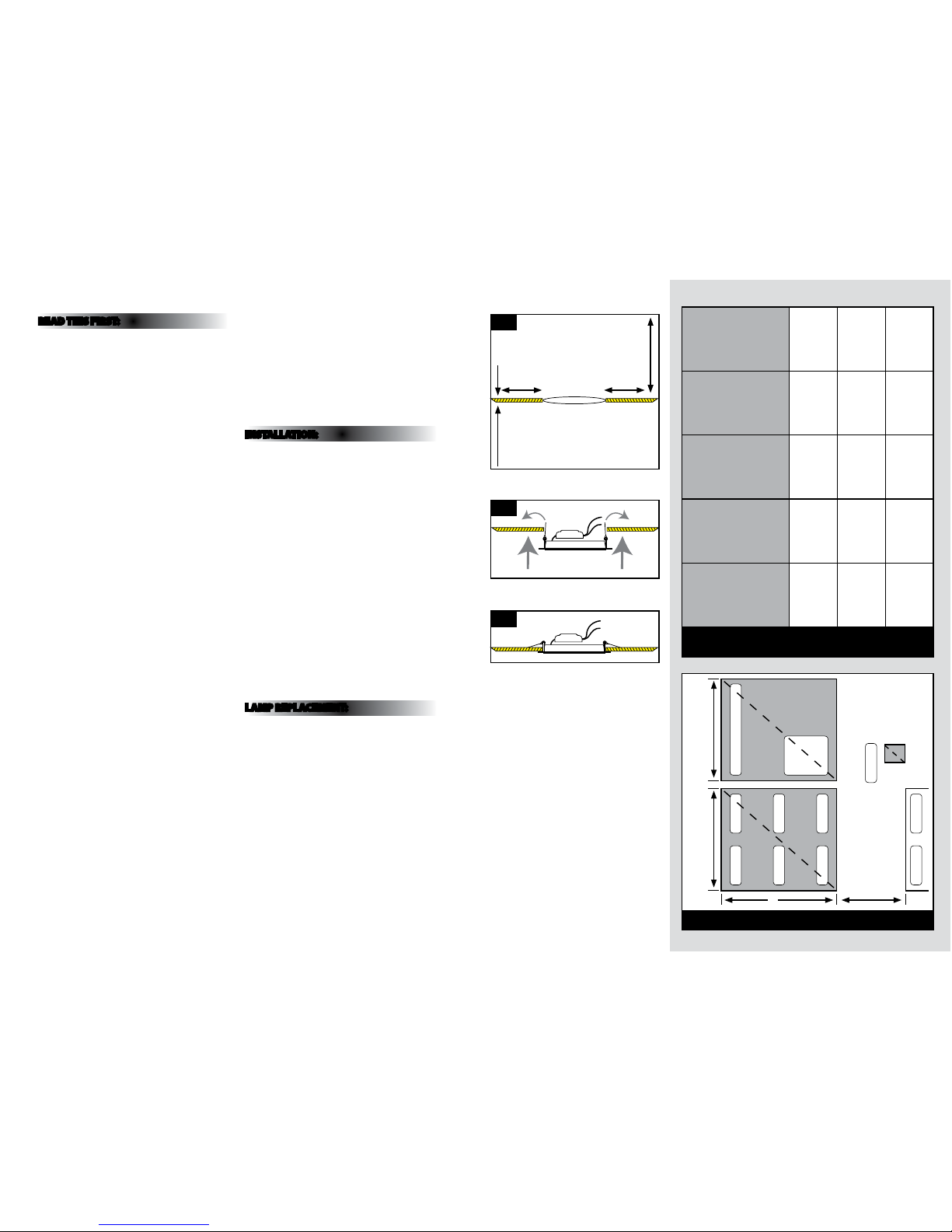
INSTALLATION:
01. Locate suitable position without obstructions
(allow minimum 75mm around the h ole for the
spring clips) and minimu m ceiling void height of
150mm. (see Fig.1 opposite).
02 . Isolate mains.
03. Make a round xing ho le in the ceiling (see sizes
below), ensuring that th e hole is cut accurately, we
recommend the us e of a circular hole cutter.
i) RDL12: 12W unit is 160mm - 164mm dia meter.
ii) RDL18: 18W unit is 220mm - 225mm diameter.
NOTE: Ensure cut-out h oles are burr free before
installations.
04. Make connec tion to driver.
05. Before feedi ng the luminaire into the hole, ensur e
the large spring cl ips point up. (See Fig. 2).
06. Feed the res t of luminaire into the hole in the
ceiling ensuring it i s ush to the mounting
surface. (See Fig . 3).
07. Switch on and test the luminaire.
LAMP REPLACEMENT:
This luminaire has a s ealed LED lamp and is
maintenance free , no lamp replacement is require d.
3m minimum dimension
between gr oups of panels
5m maximum dime nsion between
groups of pane ls 5m max
5m is maximum area
of diuser in any
one 5m x 5m
group
panel of dius er
separated groups of panels
KEY
5m
Fig 1
12W: ø 160-164mm
18W: ø 220-225mm
75mm 75mm
5-10mm
ET 150mm
Fig 2
Fig 3
Maximum
classication
of lower
surface
Use of space
below the
diusers
Maximum
area of each
diuser panel
Max total
area of
diuser
panels as
percentage
of oor area
of the space
in which the
ceiling is
located
Minimum
separation
distance
between
diuser
panels
TP (a)
Any except
protected
stairway
No limit No limit No limit
TP (b) Rooms 5.sq m 50 3M
TP (b)
Circulation
spaces except
protected
stairways
5.sq m 15 3M
LAYOUT RESTRICTIONS ON LIGHTING DIFFUSERS IN
SUSPENDED CEILINGS
LAYOUT RESTRICTIONS ON TP(b) LIGHTING DIFFUSERS
L
N
 Loading...