

Eterna PIRHL60BK, PIRHL60WH Installation Instructions Manual
These instructions are provided as a guideline to assist you.
PLEASE READ THESE INSTRUCTIONS BEFORE USING YOUR NEW FITTING
PLEASE RETAIN FOR FUTURE REFERENCE
Model:
PIRHL60BK / PIRHL60WH
Half Lantern with 120° PIR
Pack contents:
• Half lantern with 120º PIR
• Mounting xtures
LAMP REPLACEMENT:
• Switch o the elec tricity at the mains.
• Release front d iuser cover with screwdriver.
• Remove and replace l amp making sure it seats
correctly in th e lampholder.
• Replace front di user cover.
• Restore power.
REPLACEMENT LAMP TYPE:
Requires 1 x suita ble ES energy saving lamp (not
included).
Fitting is rated a t 60W max.
SPECIFICATIONS:
• Detection range: Approx. 120° (horizontal),
Max. 12 metres.
• Duration time: f rom 3 min ± 20 sec.
• Factory preset PIR - no ove rride facility.
CLEANING:
To avoid dust build-up an d ensure proper
functionin g of the half lantern light, pleas e wipe the
sensor lens light ly with a damp cloth every 3 month s.
Disconnect t he power and clean the exte rior only of
this tting wit h a moist (not wet) cloth.
Do not use any chemic al or abrasive cleaners.
EVENTUALLY, YOU MAY WANT TO
REPLACE THIS PRODUCT:
Regulations require the recycling of Waste from
Electrical and Electronic Equipment (European
“WEEE Direc tive” eective August 20 05—UK
WEEE Regulation s eective 2nd January 20 07).
Environment Agenc y Registered Producer : WEE/
GA0248Q Z.
WHEN YOUR PR ODUCT COMES TO TH E END OF
ITS LIFE OR YO U CHOOSE TO REPLACE I T, PLEASE
RECYCLE IT W HERE FACILITIES E XIST DO NOT
DISPOSE WITH HOUSEHOLD WASTE.
IF YOU EXPERIENCE PROBLEMS:
If you believe your p roduct is defective, p lease return
it to the place where yo u bought it. Our Technical
Team will gladly advise on any Eterna Lighting
product, bu t may not be able to give specic
instructions regarding individual installations.
874/2012
MODELNO.
PIRHL60 Range
INSTALLATION INSTRUCTIONS
A guide for qualied electricians
Email: sales@eterna-lighting.co.uk / technical@eterna-lighting.co.uk
Visit our website: www.eterna-lighting.co.uk
Made in ChinaIssue 0717
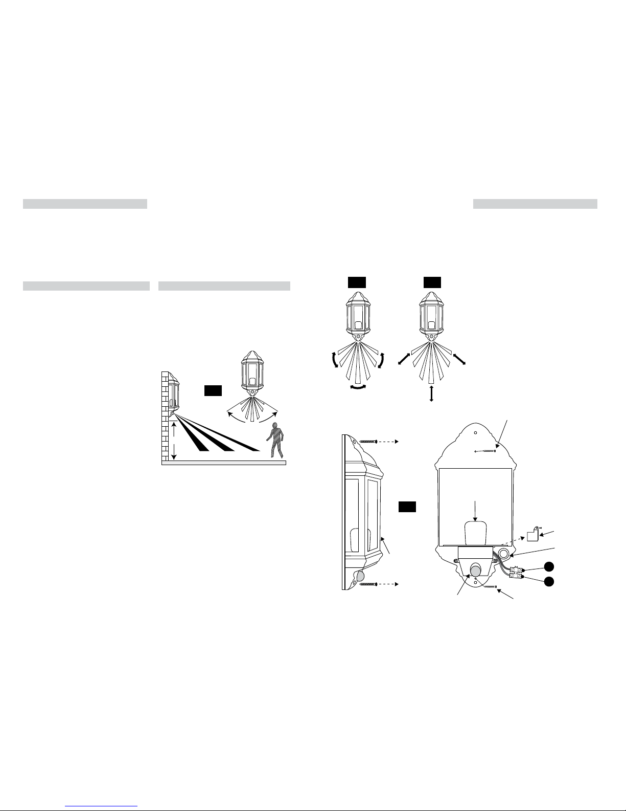
The detecti on range of the unit may also alter
with temperatu re change. Before selec ting a place
to install your PIR lant ern you should note that
movement across the s can area is more eective
than movement dire ctly towards or away from the
sensor (refer to Fig. 2 b elow).
If movement is made w alking directly towards o r
away from the senso r and not across the apparent
detection r ange will be substantially re duced (refer
to Fig. 3 below).
INSTALLATION:
Please refer to Fig. 4 b elow.
1) Remove the two screws at the top and b ottom of
the tting and li ft o the front housing.
2) Position the tting on th e surface where it is to be
installed and mark the mounting hole positions.
3) Drill and plug the wall at the m arked positions
ensuring you pass th e cable wire through rubbe r
grommet.
4) Screw and x the back housi ng to wall with
suitable mounting screws (supplied).
5) Remove PIR terminal cover and e xpose the
connector block and make connections according
to the relatives sy mbols:
(L) Brown wire
(N) Blue wire.
Make sure that terminals are tightened securely and
that no strands of w ire protrude.
6) Replace and secure the p lastic PIR cover.
7) Insert suitable ES energy saving lamp.
8) Replace the front housi ng and tighten the screws.
9) Restore the power a nd switch on.
INTRODUCTION:
The half lantern i ncorporates a PIR (passive Infr ared)
sensing device wh ich continuously scans a prese t
operating zon e and immediately switches th e light
on when it detec ts movement in that area.
This means that whe never movement is detecte d
within the range o f the sensor the light will switch
on automaticall y to illuminate the area you have
selected to l ight. While there is movement wi thin
range of the unit th e light will remain on.
READ THIS FIRST:
Check the pack and m ake sure you have all of the
parts liste d on the front of this bookle t. If not,
contact the outlet where you bought this product.
This produ ct must be install ed by a competent
person in accordance with the current building
and IEE wiring regulations.
As the buyer, install er and/or user of this product it
is your own responsi bility to ensure that this tt ing
is t for the purpo se for which you have intended
it. Eterna lightin g cannot accept any liability fo r
loss, damage or premature failure resulting from
inappropriate use.
This product is designed and constructed according
to the principles o f the appropriate British Stan dard
and is intended fo r normal domestic ser vice. Using
this tting in any oth er environments may result in a
shortened working life.
Switch o the mains be fore commencing installati on
and remove the appro priate circuit fuse or lock o
MCB.
This unit is suitab le for outdoor use.
This produc t is designed for permanent co nnection
to xed wiring: this m ust be a suitable circuit
(protected w ith the appropriate MCB or fuse).
Before makin g xing hole(s), check that there are no
obstructi ons hidden beneath the mount ing surface
such as pipes or cab les.
Make sure that the xi ngs are strong enough to
support the co nsiderable weight of the t ting and
hold it rigidly.
The lamp must be p ositioned so that there is at lea st
0.5m (500mm) bet ween the bulb and any illuminated
surface.
When making con nections ensure that the ter minals
are tightened se curely and that no strands of wi re
protrude. Chec k that the terminals are tightene d
onto the bared cond uctors and not onto any
insulation.
WARNING: This prodct becom es hot!
This produc t is not intended to be used by childr en
and persons wi th sensory, physical and/or ment al
impairments th at would prevent them from using i t
saf ely.
IMPORTANT - Always switc h o the mains power
before changing the lamp.
You are advised at ever y stage of your installatio n to
double-check any electrical connections you have
made. After you h ave completed your installatio n
there are elec trical tests that should b e carried out,
these tests are sp ecied in the current IEE wir ing and
building regulations.
This produc t is double insulated, do not conn ect any
part to eart h.
WHERE TO F IT YOUR PIR HALF LANT ERN:
To achieve best results we su ggest you take the
following points into consideration:
Do not mount on a sur face that has vibration.
Ideally the PIR hal f lantern should be mounted 1.8
to 2.5 metres (6 to 8f t) above the area to be scanne d
(refer to Fig. 1 below).
To avoid damage to the unit do not ai m sensor
towards the sun.
Avoid positioning th e sensor unit adjacent to a
bright light source w hich may prevent the unit from
operating whe n the lux control is set to operate i n
dark conditions.
Avoid nuisance false t riggering by directing s ensor
away from:
Trees and shrubs
Reective su rfaces such as smooth white w alls
Swimming pools
Heat sources such as b oiler ues
The PIR sensor sc anning specications
(approximately 12 metres at 120°) may var y slightly
depending on the mounting height and location.
1.8-2.5M
4M 8M 12M
120˚
Appr.
L
Brown
(power cable)
Rubber
Grommet
Plastic
Cover
Blue
(power cable)
N
Fixing Wall
Screw
Fig 1
Fig 4
1.8-2.5M
4M 8M 12M
120˚
Appr.
PIR
Sensor
L
Brown
(power cable)
Rubber
Grommet
Plastic
Cover
Lamp
Holder
Fixing Wall
Screw
Blue
(power cable)
N
Fixing Wall
Screw
Front
Housing
Fig 2 Fig 3
EFFECTIVE
LESS EFFECTIVE
L
Brown
(power cable)
Rubber
Grommet
Plastic
Cover
Lamp
Holder
Fixing Wall
Screw
Blue
(power cable)
N
Front
Housing
PIR
Sensor
L
Brown
(power cable)
Rubber
Grommet
Plastic
Cover
Lamp
Holder
Fixing Wall
Screw
Blue
(power cable)
N
Fixing Wall
Screw
 Loading...