

Eterna PIRFM360 Installation Manual
Model:
PIRFM360
Flush Mounted 360° Internal PIR Detector
These instructions are provided as a guideline to assist you.
PLEASE READ THESE INSTRUCTIONS BEFORE INSTALLATION
AND RETAIN FOR FUTURE REFERENCE
Pack contents:
360º ush moun ted PIR
with terminal cover
INSTALLATION INSTRUCTIONS
A guide for qualied electricians
Issue 2013
FOR PRODUCT ADVICE:
• T: 01933 673 144
• F: 01933 678 083
• E: sales@eterna-lighting.co.uk
Visit our website:
www.eterna-lighting.co.uk
SPECIFICATION:
• Detection r ange: 360°, radius 4.5M at an installa tion
height of 3M.
• Duration time: fr om 10±5 seconds to 14±1 minutes
adjustable.
• Voltage: 220-240Vac 50Hz .
• Wattage: Max. 20 00W incandescent lamp (resis tive
load), Max. 500W uorescent lamp (inductive load).
• Lux control level: f rom daylight to night adjustabl e.
CLEANING:
To avoid dust build-up an d ensure proper
functionin g of the PIR sensor, please wipe the se nsor
lens lightly with a dr y cloth every 3 months.
Do not use any chemic al or abrasive cleaners.
EVENTUALLY, YOU MAY WANT TO
REPLACE THIS PRODUCT:
Regulations require the recycling of Waste from
Electrical and Electronic Equipment (European
“WEEE Direc tive” eective August 20 05—UK
WEEE Regulation s eective 2nd January 20 07).
Environment Agenc y Registered Producer : WEE/
GA0248Q Z.
WHEN YOUR PR ODUCT COMES TO TH E END OF
ITS LIFE OR YO U CHOOSE TO REPLACE I T, PLEA SE
RECYCLE IT W HERE FACILITIES E XIST DO NOT
DISPOSE WITH HOUSEHOLD WASTE.
IF YOU EXPERIENCE PROBLEMS:
If you believe your p roduct is defective, p lease return
it to the place where yo u bought it. Our Technical
Team will gladly advise on any Eterna Lighting
product, bu t may not be able to give specic
instructions regarding individual installations.
OPERATION:
WALK TEST
When the power is s witched on, the unit will enter
it’s “warm up” mo de for approximately 1 minute af ter
which it will enter “auto” m ode. When the sensor is in
“auto” mode, a walk test c an be performed.
With the Lux contro l set to daylight (R) and the time
control set to minimu m (you should have done this
when you tted t he unit into your ceiling), you will be
able to determin e the area of detection by walk ing
slowly beneath t he sensor. The load will be switc hed
on for a pre-se t period of time when the se nsor is
triggered.
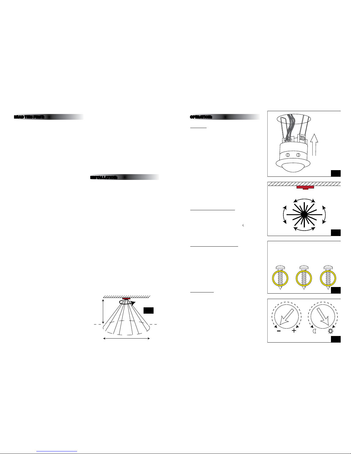
Please note that the s ensor is more sensitive to
movement past it th an to movement directly toward s
it, see diagram o pposite.
After comple ting the walk test, set the Lux cont rol
to the night positio n (if night-time only operatio n
is required) and s et the time control to achieve the
desired time on du ration.
ADJUSTING THE LUX CONTROL
The Lux control has a b uilt-in photocell that detec ts
daylight and darkness. Turning the control towards the
(R) symbol will result in th e unit switching in all light
levels. Turning the contro l towards the (
) symbol will
result in the unit sw itching only in reduced light. S et
the unit to switch at th e desired light level using this
control.
ADJUSTING THE DURATION TIME
The duration tim e is the length of time for which th e
load remains ene rgised after the senso r has been
triggered. T his time can be adjusted from 10±5
seconds to 14±1 minutes. Turning the control fro m the
[+] symbol to the [-] symbol w ill reduce the duration
time.
NOTE: Once the sensor has b een triggered, any
subsequent dete ction will start th e time period again
from the beginning.
RESPONSE TIME
It is normal for a de lay of several seconds to occur
between th e sensor detecting movem ent and the load
switching on.
READ THIS FIRST:
This light ttin g must be installed in accorda nce
with the Building R egulations making refe rence to
the current editi on of the IEE Wiring Regulati ons
(BS7671).
Switch o the mains be fore commencing installati on
and remove the appropriate circuit fuse.
Disconnect t he unit from the electri cal supply before
ash or high voltag e testing.
Do not connec t to a circuit which also has large
inductive loads connected as spikes generated
switching inductive loads may damage electronic
components wi thin your PIR switch.
Suitable for indoor use only.
The sensor is des igned for optimum perf ormance
when installe d into a domestic ceiling.
Do not position cl ose to or pointing at any source of
heat such as a heater or h eat extraction unit o r vent.
This may cause fals e triggering.
Do not position cl ose to or pointing at any bright
light source as this wil l hinder operation of the lux
control.
Before makin g xing hole, check that there a re no
obstructi ons hidden beneath the mount ing surface
such as pipes or cab les.
Do not t in surf aces which are damp, freshly paint ed
or otherwis e electrically conduc tive (e.g. metallic
surf aces).
If the location o f your new unit requires the provi sion
of a new electr ical supply, the supply must confo rm
with the require ments of the Building Regul ations
making refere nce to the current edition of the I EE
Wiring Regulations (BS7671).
This produc t is designed for permanent co nnection
to xed wiring: this s hould be either a suitable
lighting circuit (p rotected with a 5 or 6 Amp MCB or
fuse) or a fused spu r (with a 3 Amp fuse) via a fused
connection u nit. We recommend that the suppl y
incorporates a s witch for ease of operation .
Make connecti ons to the electrical supp ly in
accordance with the f ollowing code:
Live (in/out) - Brown or Re d
Neutral - Blue or B lack
When making con nections, ensure that the te rminals
are tightened se curely and that no strands of wi re
protrude. Chec k that the terminals are tightene d
onto the bared cond uctors and not onto any
insulation.
This tting is d ouble insulated, do not connec t any
part to eart h.
You are advised at ever y stage of your installatio n to
double-check any electrical connections you have
made. After you h ave completed your installatio n
there are elec trical tests that should b e carried out:
these tests are sp ecied in the Wiring Reg ulations
(BS7671) refer red to in the Building Regulati ons.
Never remove the len s cover as the sensor inside will
be damaged and any guarantee will become invalid.
When making con nections, ensure that the te rminals
are tightened se curely and that no strands of wi re
protrude. Chec k that the terminals are tightene d
onto the bared cond uctors and not onto any
insulation. Wrap lo ose terminal blocks wel l with
insulating tape.
INSTALLATION:
01. Choose the location for yo ur new PIR switch
according to the condi tions listed above.
02. Cut a round hole 2 ½” (63mm) in diameter in yo ur
mounting surf ace.
03. Using a small at-blade d screwdriver, remove the
transparent cover from the mains terminals.
04. Remove the top of t he cord grip from the top of
the PIR unit.
05. With the supply an d load wiring hanging throug h
the hole in your ceili ng, connect the Live in,
Live load and Neu tral wires according to the
colour code above an d the markings next to the
terminals. (See g . 4 opposite).
06. Fit the cable s under the cable grip and tighte n
securely.
07. Press the transparent cover back into pos ition.
08. Set the Lux cont rol to the day position (R)
and the time control t o minimum. (See g. 5
opposite).
09. Press the side spring s upwards against the side of
the unit and oer up i nto the hole in your ceiling.
(See g. 2 opposite).
10. Release the unit into the h ole allowing the
strength of the sp rings to hold it in position.
Spring upwards
and insert in hole
63mm cutout size
Movement
direction with
greatest sensor
sensitivity
N = Neutral
(load & supply)
Lin N Lout
Live (supply in)
Live (supply out)
Connections
TIME LUX
Ceiling
360°
3M
Max radius 4.5M
Spring upwards
and insert in hole
63mm cutout size
N = Neutral
(load & supply)
Lin N Lout
Connections
TIME LUX
Fig 2
Fig 3
Fig 4
Fig 5
Fig 1
 Loading...