

Page 1
Issue 2013
HELPLINE:
• T: 01933 673 144
• F: 01933 678 083
• E: sales@eterna-lighting.co.uk
Visit our website:
www.eterna-lighting.co.uk
These instructions are provided as a guideline to assist you.
PLEASE READ THESE INSTRUCTIONS BEFORE USING YOUR NEW FITTING
PLEASE RETAIN FOR FUTURE REFERENCE
Model:
PIRF120BK / PIRF120WH / PIRF400BK / PIRF400WH
120W / 400W 180º PIR Halogen Floodlights
Pack contents:
1 x Floodlight
1 x Linear Halogen Lamp
INSTALLATION INSTRUCTIONS
A guide for qualied electricians
PI RF120 WH
PIRF400 BK
1M
EVENTUALLY, YOU MAY WANT TO REPL ACE THI S PRODUCT:
Regulations re quire the recycling of Waste fr om Electrical and Elec tronic Equipment (European “ WEEE
Directive” e ective August 2005— UK WEEE Regulations eec tive 2nd January 2007). Environmen t Agency
Registered Pro ducer: WEE/GA0248QZ.
WHEN YOUR PR ODUCT COMES TO TH E END OF ITS LIFE OR YOU CH OOSE TO REPLACE IT, PLEA SE RECYCLE IT
WHERE FACILI TIES EXIST DO N OT DISPOSE WITH HO USEHOLD WASTE.
IF YOU EXPERIENCE PROBLEMS:
If you believe your p roduct is defective, p lease return it to the place whe re you bought it. Our Technical Team
will gladly adv ise on any Eterna Lighting produc t, but may not be able to give spe cic instructions rega rding
individual installations.
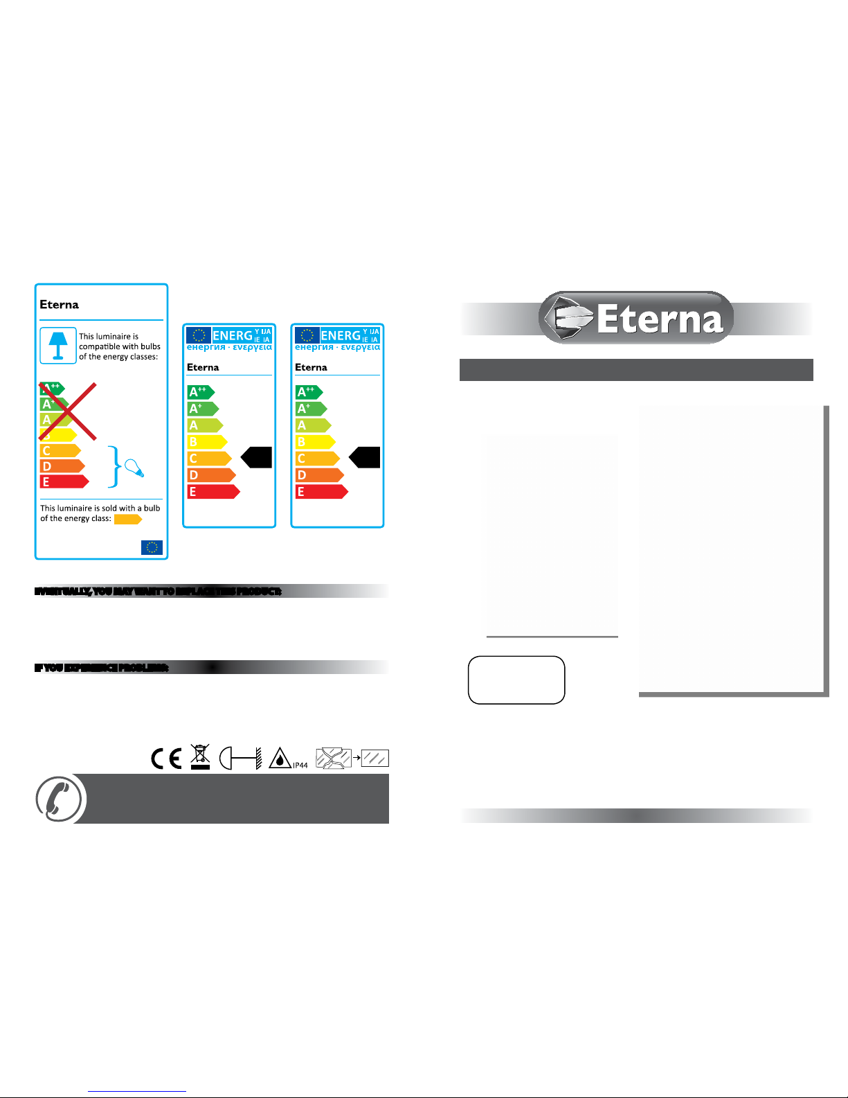
874/2012
C
MODELNO.
PIRF Range
MODELNO.
A
++
XXX kWh/1000h
120
PIRF120BK / WH
C
MODELNO.
A
++
XXX kWh/1000h
400
PIRF400BK / WH
C
Page 2
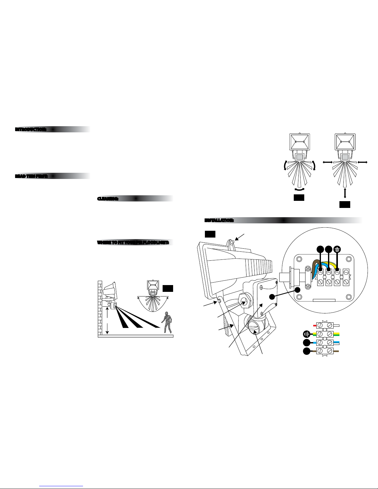
Fig 1
Avoid nuisance / false t riggering by directing s ensor
away from:
• Trees and shrubs
• Reective su rfaces such as smooth white w alls
• Swimming pools
• Heat sources such as b oiler ues
The PIR sensor sc anning specications
(approximately 12 metres at 180°) may v ary slightly
depending on the mounting height and location.
The detecti on range of the unit may also alter w ith
temperature cha nge. Before selectin g a place to
install your PIR o odlight you should note that
movement across the s can area is more eective
than movement dire ctly towards or away from the
sensor. (Refer g.2).
If movement is made w alking directly towards o r
away from the senso r and not across the sensor
the apparent dete ction range will be subs tantially
reduced (refer g . 3).
Fig 3
INTRODUCTION:
The oodlight i ncorporates a PIR (Passive Infra R ed)
sensing device wh ich continuously scans a prese t
operating zon e and immediately switches th e light
on when it detec ts movement in that area.
This means that whe never movement is detecte d
within the range o f the sensor the light will switch
on automaticall y to illuminate the area you have
selected to l ight. While there is movement wi thin
range of the unit th e light will remain on.
READ THIS FIRST:
Check the pack and m ake sure you have all of the
parts liste d on the front of this bookle t. If not,
contact the outlet where you bought this product.
This produc t contains glass, care must be take n when
assembling, t ting or handling to prevent per sonal
injury or damag e to the product.
This produc t must be installed by a compet ent
person in accord ance with the current building a nd
IEE wiring regulations.
As the buyer, install er and/or user of this product it
is your own responsi bility to ensure that this tt ing
is t for the purpo se for which you have intended
it. Eterna Lightin g cannot accept any liability fo r
loss, damage or premature failure resulting from
inappropriate use.
This product is designed and constructed according
to the principles o f the appropriate British Stan dard
and is intended fo r normal domestic ser vice. Using
this tting in any oth er environments may result in a
shortened working life.
Switch o the mains be fore commencing installati on
and remove the appro priate circuit fuse or lock o
MCB.
When replacin g the lamp, do not touch with bare
ngers, grip th e lamp with a tissue or clean sof t cloth.
This unit is suitab le for outdoor use.
This produc t is designed for permanent co nnection
to xed wiring: this m ust be a suitable circuit
(protected w ith the appropriate MCB or fuse).
Before makin g xing hole(s), check that there are no
obstructi ons hidden beneath the mount ing surface
such as pipes or cab les.
Make sure that the xi ngs are strong enough to
support the co nsiderable weight of the t ting and
hold it rigidly.
The lamp must be p ositioned so that there is at lea st
1M between the bulb an d any illuminated surface.
When making con nections ensure that the ter minals
are tightened se curely and that no
strands of wire p rotrude. Check that the termin als are
tightened onto the b ared conductors and not o nto
any insulation.
This produc t must be connected to ear th
termination.
WARNING: This product becomes hot!
This produc t is not intended to be used by childr en
and persons wi th sensory, physical and/or ment al
impairments th at would prevent them from using i t
saf ely.
IMPORTANT - Always s witch o the mains p ower
before changing the lamp.
You are advised at ever y stage of your installatio n to
double-check any electrical connections you have
made. After you h ave completed your installatio n
there are elec trical tests that should b e carried out,
these tests are sp ecied in the current IEE wir ing and
building regulations.
CLEANING:
• To avoid dust build-up and ensur e proper
functionin g of the oodlight, please w ipe the
sensor lens light ly with a damp cloth every 3
months.
• Disconnect the po wer and clean the exterior o nly of
this tting wit h a moist (not wet) cloth.
• Do not use any chemic al or abrasive cleaners.
WHERE TO F IT YOUR PIR FLOODLIGHT:
To achieve best results we su ggest you take the
following points into consideration:
Do not mount on a sur face that has vibration.
Ideally the PIR o od light should be mounted 1.8 to
2.5 metres (6 to 8f t) above the area to be scanned
(refer to g.1 below).
To avoid damage to the unit do not ai m sensor
towards sun.
Avoid positioning th e sensor unit adjacent to a
bright light source w hich may prevent the unit from
operating whe n the lux control is set to operate i n
dark conditions.
Yellow/Green
(Power Cable)
Blue / White
(Power Cable)
Brown
(Power Cable)
White
(Lamp Wire)
Yellow / Green
(power cable)
2.5M
4M 8M 12M
180˚
Appr.
Eective
Less
Eective
Fig 2
INSTALLATION:
LN
Yellow/Green
(Power Cable)
Blue / White
(Power Cable)
Brown
(Power Cable)
Yellow/Green
(Earth)
Blue
(Power Cable)
Brown
(Power Cable)
RED (PIR Switch Wire)
White
(Lamp Wire)
Terminal Block
Power
Cable
L N
Brown (power cable)
Blue
(power
cable)
Yellow / Green
(power cable)
Lamp Cover Screw
Cable Gland
Wall Mounting
Support Screws
Wall Mounting
Support Bracket
Junction Box
Locking Nut
Fig 4
Page 3

Fig 5
INSTALLATION:
When installin g the PIR ood light refer to Fig.4 o n
the previous page.
01) Switch o the mains be fore commencing
installation.
02) Remove th e wall bracket from the ttin g by
removing the scr ews and nuts from each side.
Take care not to lose any of these p arts as the
nuts are not capti ve within the tting - see g. 4.
03) Using the b racket as a template mark and then
drill the appropriate xing holes.
04) Se cure the bracket with suitab le xings (not
supplie d).
05) Unscr ew the junction box cover screws a nd
remove cover, unscrew the glan d nut and loosen
the cable restr aint clamp. Connect the power
cable (not include d) to the terminal block, s ee
g. 4. Ensure the cab le passes through the cable
gland and gasket.
06) Re -t the terminal block , tighten the cable
restraint clamp, tighten the gland nut and re-t
the c over.
07) Fix ho using back into wall mounting bra cket and
secure with screws, washers and nuts previously
removed.
08) Uns crew the lamp cover screw and inser t the
lamp making sure it i s correctly seated in the
lampholder (do no t touch the bulb with bare
hands use a sof t cloth) then re-x the cover.
09) Adjus t the direction of the oo dlight and tighten
the head xings e nsuring that you have used the
lock washers.
10) Restore mains power.
11) Ad just the PIR sensor oodligh t to the desired
settings.
IMPORTANT
Loosen the lock n uts and screws on sensor and
oodlight before making any adjustments.
UNDERSTANDING THE CONTROLS:
(Referring to Fig.5 above)
ADJUSTING TH E DURATION TIME:
The length of tim e that unit remains switched on
after acti vation can be adjusted fro m (5±1) seconds
to (8±1) minutes app roximately. Rotating the TIME
knob from (+) to (-) will reduce the dur ation time.
Note: Once the light has be en triggered by the PIR
sensor any subseq uent detection will sta rt the timed
period again from the beginning.
ADJUSTING TH E LUX CONTROL LEVEL:
The Lux control mo dule has a built-in sensing device
(photocell) that d etects daylight and dark ness. The
(R) position denotes that th e oodlights can work
at day and night, and the () p osition only work at
night. You can set to oper ate the unit at the desired
level by adjusting t he LUX knob.
ADJUSTING TH E SENSITIVITY:
The sensitivi ty means the maximum dist ance which
PIR sensor can be tr iggered by movement - turning
the SENS knob fro m (+) to (-) will decrease th e
sensitivity.
SETTING THE CONTROLS:
WALK TEST
Turn the Lux control knob to li ght (R) ensure that the
TIME control kn ob is set at minimum duration time
(-) position (rotating th e TIME knob anti-cloc kwise
to stop-po sition). The oodlight will now sw itch on
and remain on for ab out 5-15 seconds af ter each
detection.
01) Direct the se nsor toward the desired area to be
scanned by adjus ting the swivel joint on the
sensor arm.
Important: loosen the lock nuts and screws
on sensor and oodlight before making any
adjustments.
02) Have anoth er person move across the center
of the area to be scan ned and slowly adjust the
angle of the senso r arm until the unit senses
the presence of th e moving person, causing th e
oodlight to swi tch on (refer to Fig. 2).
03) Adjust time control to required setting.
04) To set the lig ht level at which the oodlight wi ll
automatically s witch “on” at night, turn the LUX
control knob fr om daylight (R) to night (). If the
oodlight is req uired to switch on earlier, e.g.
dusk, wait for th e desired light level, then slow ly
turn the LUX control kn ob towards daylight while
someone walk s across the center of the area to
be detecte d. When the oodlight switc hes on,
release the LUX contro l knob. You may need to
make further a djustments to achieve your ide al
light level set ting.
LN
TIME LUXSENS
Yellow/Green
(Power Cable)
Blue / White
(Power Cable)
Brown
(Power Cable)
Yellow/Green
(Earth)
Blue
(Power Cable)
Brown
(Power Cable)
RED (PIR Switch Wire)
White
(Lamp Wire)
Terminal Block
Power
Cable
L N
Brown (power cable)
Blue
(power
cable)
Yellow / Green
(power cable)
Lamp Cover Screw
Locking Nut
TROUBLESHOOTING AND USER HINTS:
Note: all passive infra re d detectors are more se nsitive in cold and dry weather th an warm and wet weather.
PROBLEM POSSIBLE CAUSE SUGGESTED REMEDY
Light does not switch on
when there is movement
in the detection area.
1. No mains voltage Check all connections, and MCB Fuses / switches
2. Nearby lighting is too bright Redirect sensor or relocate the unit
3. Controls set incorrectly Readjust sensor angle or control knob
4. Lamp blown Check lamp functions and replace if necessary
5. Lamp not tted correctly
Make sure the lamp is correctly seated in the
lampholder
6. Wired incorrectly
Check wiring and conrm its wired as per the
wiring diagram
7. Sensor positioned in wrong direction
Adjust angle and direction of PIR for best results
walk across beam
Light switches on for no
apparent reason (false
trigger)
1. Heat from lamp body activating sensor
Adjust PIR sensor or oodlight to allow a
minimum gap of 40mm between oodlight body
and sensor head
2. Heat sources such as air-con, vents, heaters, ues,
other outside lighting, moving cars trees or shrubs
are activating sensor
Adjust direction of sensor head away from these
sources. Reduce sensitivity (if available)
3. Animals / birds activating sensor
Redirecting sensor head may help (Reduce
sensitvity settings)
4. I nterference from on/o switching of electric
fans or lights on the same circuit as your security
oodlight.
(This problem does not always occur but a faulty
switch or noisy uorescent light may cause the
security oodlight to switch on)
Should the false triggering become, troublesome,
consider:
(a) Replacing a faulty switch
(b) Replacing noisy uorescent tubes and/or
starters
(c) Connecting the oodlight to a separate
circuit (in most cases where one or more of
the above suggestions have been carried out,
false triggering has been reduced)
5. Reec tion from swimming pool, or reective
surface such as smooth white walls
Redirect sensor
Light remains on
1. Continuously false triggered Redirecting sensor head may help
2. Time is set too long Reduce time
Light remains on at
nighttime
Possible heat source in detection zone
Cover PIR sensor lens with a thick cloth, if the
light turns o check detection area for heat or
reective source, reposition head and decrease
the sensitivity setting if this control is available
Light switches on during
daylight hours
LUX control knob is set to daylight position
Turn the LUX control knob to desired light level
setting
When setting the lux
controls in daylight
the detection distance
becomes shorter
Interference by sunlight Re-test at night
Page 4

LAMP REPLACEMENT:
For breakage information visit:
www.eterna-lighting.co.uk
• Switch o the elec tricity at the mains.
• Release front cove r.
• Remove and replace l amp making sure it sits
correctly in th e lampholder. Do not use bare ng ers.
• Replace front s afety glass ensuring gasket is tted
correctly and secure with single screw.
• Restore power.
REPLACEMENT LAMP TYPE:
Wattage: 120W / 400W
Supply Voltage: 240V
Type: R7s Linear Halogen
SPECIFICATIONS:
• Det ection range: Max. 12M at approx. 180° s can
• Dur ation time adjustment: (5-10) seconds to (8±1)
minutes
• Detection c ircuitry: Passive Infra -Red (PIR)
• Weatherproof : IP44
• Power required: 230V~ 50 Hz
• Ma ximum load: 120W R7s Linear Halogen
(PIRF120BK / PIRF120WH)
• Ma ximum load: 400W R7s Linear Halog en
(PIRF400 BK / PIRF400WH)
• Re commended power supply ca ble: H05RN-F 3G
1.0m m
2
• Protection: Cla ss I
• Tempered Glass
SPECIFICATIONS:
PIR120BK / WH PIR400BK / WH
Voltage 240V 240V
Frequency 50Hz 50Hz
Nominal lumens
2218 lm 8550 lm
Wattage 120W 400W
Nominal life time of the lamp 2,000 hrs 2,000 hrs
Number of switching cycles
before premature lamp
failure
8,000 8,000
Colour temperature 2800K 2800K
Warm-up time up to 60 % of
the full light output
Instant full light Instant full light
Dimmable Yes Yes
Lamp dimensions (mm) 78 x 10 118 x 10
Cap type R7s R7s
 Loading...