

Page 1
110913-BT
Pack contents:
Bulkhead x 1
Fixing Kit x 1
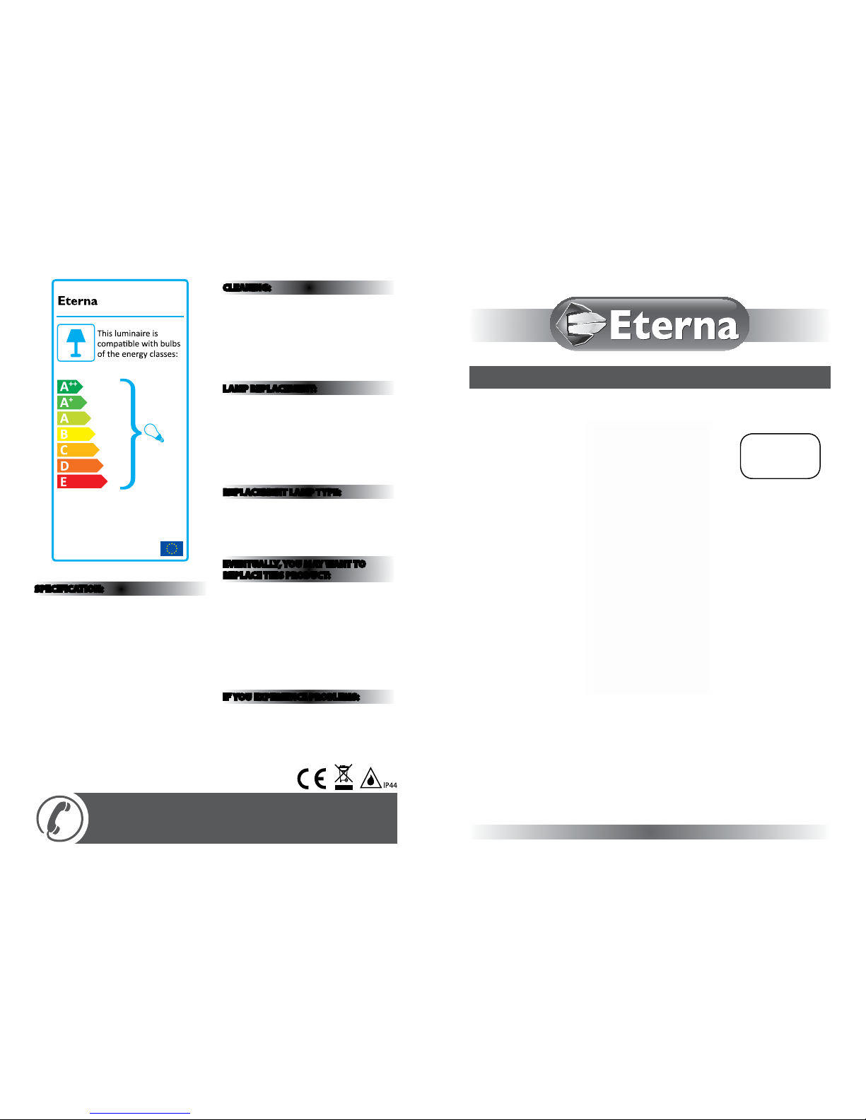
874/2012
MODELNO.
PIR80BK
FOR PRODUCT ADVICE:
• T: 01933 673 144
• F: 01933 678 083
• E: sales@eterna-lighting.co.uk
Visit our website:
www.eterna-lighting.co.uk
Model:
PIR80BK
Bulkhead with 120° PIR
These instructions are provided as a guideline to assist you.
PLEASE READ THESE INSTRUCTIONS BEFORE INSTALLATION
AND RETAIN FOR FUTURE REFERENCE
INSTALLATION INSTRUCTIONS
A guide for qualied electricians
SPECIFICATION:
• Detection range: Approx 120° (horizontal),
max. 12 metres
• Duration time f rom: (10±5) seconds to (4±1)
minutes adjustable
• Weatherproof : IP44
• Voltage: 230V ~ 50 Hz
• Wattage: The tting is rated at
60W max.
• LUX control level: From daylight to night
adjustable
• Protection: Class I
CLEANING:
• To avoid dust build-up and e nsure proper
functionin g of the bulkhead light, ple ase wipe
the sensor lens li ghtly with a damp cloth every 3
months.
• Disconnect th e power and clean the exter ior only of
this tting wit h a moist (not wet) cloth.
• Do not use any chemic al or abrasive cleaners.
LAMP REPLACEMENT:
• Switch o the elec tricity at the mains.
• Release front d iuser cover with screwdriver.
• Remove and replace la mp making sure it sits
correctly in th e lampholder.
• Replace front di user cover by hand.
• Restore power.
REPLACEMENT LAMP TYPE:
Requires 1 x suita ble BC energy saving lamp.
Wattage: Fitting is rated at 60W
Supply Voltage: 230V
Typ e: B22
EVENTUALLY, YOU MAY WANT TO
REPLACE THIS PRODUCT:
Regulations require the recycling of Waste from
Electrical and Electronic Equipment (European
“WEEE Direc tive” eective August 20 05—UK
WEEE Regulation s eective 2nd January 20 07).
Environment Agenc y Registered Producer : WEE/
GA0248Q Z.
WHEN YOUR PR ODUCT COMES TO TH E END OF
ITS LIFE OR YO U CHOOSE TO REPLACE I T, PLEA SE
RECYCLE IT W HERE FACILITIES E XIST DO NOT
DISPOSE WITH HOUSEHOLD WASTE.
IF YOU EXPERIENCE PROBLEMS:
If you believe your p roduct is defective, p lease return
it to the place where yo u bought it. Our Technical
Team will gladly advise on any Eterna Lighting
product, bu t may not be able to give specic
instructions regarding individual installations.
Page 2

The PIR sensor sc anning specications
(approximately 12 metres at 120°) may var y slightly
depending on the mounting height and location.
The detecti on range of the unit may also alter w ith
temperature cha nge. Before selectin g a place to
install your PIR bul khead you should note that
movement across the s can area is more eective
than movement dire ctly towards or away from the
sensor. (refer to Fig. 2).
If movement is made w alking directly towards o r
away from the senso r and not across the apparent
detection r ange will be substantially re duced (refer
to Fig. 3).
INTRODUCTION:
The bulkhea d light incorporates a PIR (passive I nfra
red) sensing dev ice which continuously scans a
preset opera ting zone and immediately sw itches the
light on when it det ects movement in that area.
This means that whe never movement is detecte d
within the range o f the sensor the light will switch
on automaticall y to illuminate the area you have
selected to l ight. While there is movement wi thin
range of the unit th e light will remain on.
READ THIS FIRST:
Check the pack and m ake sure you have all of the
parts liste d on the front of this bookle t. If not,
contact the outlet where you bought this product.
This produ ct must be install ed by a competent
person in accordance with the current building
and IEE wiring regulations.
As the buyer, install er and/or user of this product it
is your own responsi bility to ensure that this tt ing
is t for the purpo se for which you have intended
it. Eterna Lightin g cannot accept any liability fo r
loss, damage or premature failure resulting from
inappropriate use.
This product is designed and constructed according
to the principles o f the appropriate British Stan dard
and is intended fo r normal domestic ser vice. Using
this tting in any oth er environments may result in a
shortened working life.
Switch o the mains be fore commencing installati on
and remove the appro priate circuit fuse or lock o
MCB.
This unit is suitab le for outdoor use.
This produc t is designed for permanent co nnection
to xed wiring: this m ust be a suitable circuit
(protected w ith the appropriate MCB or fuse).
Before makin g xing hole(s), check that there are no
obstructi ons hidden beneath the mount ing surface
such as pipes or cab les.
Make sure that the xi ngs are strong enough to
support the co nsiderable weight of the t ting and
hold it rigidly.
The lamp must be p ositioned so that there is at lea st
0.5m (500mm) bet ween the bulb and any illuminated
surface.
When making con nections ensure that the ter minals
are tightened se curely and that no strands of wi re
protrude. Chec k that the terminals are tightene d
onto the bared cond uctors and not onto any
insulation.
This produc t must be connected to ear th
termination.
WARNING: This product becomes hot!
This produc t is not intended to be used by childr en
and persons wi th sensory, physical and/or ment al
impairments th at would prevent them from using i t
saf ely.
IMPORTANT: Always switch o the mains power
before changing the lamp.
You are advised at ever y stage of your installatio n to
double-check any electrical connections you have
made. After you h ave completed your installatio n
there are elec trical tests that should b e carried out,
these tests are sp ecied in the current IEE wir ing and
building regulations.
WHERE TO F IT YOUR PIR BULKH EAD:
To achieve best results we su ggest you take the
following points into consideration:
Do not mount on a sur face that has vibration.
Ideally the PIR bul khead light should be mounte d 1.8
to 2.5 metres (6 to 8f t) above the area to be scanne d
(refer to Fig. 1 below).
To avoid damage to the unit do not ai m sensor
towards the sun.
Avoid positioning th e sensor unit adjacent to a
bright light source w hich may prevent the unit from
operating whe n the lux control is set to operate i n
dark conditions.
Avoid nuisance false t riggering by directing s ensor
away from:
Trees and shrubs
Reective su rfaces such as smooth white w alls
Swimming pools
Heat sources such as b oiler ues
Blue
(power cable)
Yellow / Green
(power cable)
L N
Terminal Block
Diffuser
Lamp Holder
Mounting Screws (2Pcs) Screwdriver
Brown
(power cable)
Screw (A)
Transparent
Plate
Good Less Eective
INSTALLATION:
Blue
(power cable)
Yellow / Green
(power cable)
L N
Terminal Block
Diffuser
Lamp Holder
Mounting Screws (2Pcs) Screwdriver
Brown
(power cable)
Screw (A)
Transparent
Plate
Fig 4
When installin g the PIR bulkhead light, plea se refer
to Fig. 4 above.
01) Switch o the mains power before comm encing
installation.
02) Remove the diuser usin g a screwdriver, see Fig.
4 above.
03) Unscrew the screw (A) and rem ove the
transparent terminal cover plate.
04) Position the tt ing on the surface where it s to be
installed and m ark the mounting hole positi ons.
Drill and plug the w all at the marked positions
and pass cable wi re through rubber grommet .
Screw and x the lamp b ody to wall with suitable
mounting screws (supplied).
05) Connect the main p ower wires to the terminal
block (see the rel ative symbols - Fig. 4 above).
06) Insert the lam p into the (B22) lampholder.
07) Re-screw transparent plate.
08) Ret the diuse r.
09) Restore power, wait 30 se conds for circuit to
stabilise.
10) Set controls.
Blue
(power cable)
Yellow / Green
(power cable)
L N
2.5M
4M 8M 12M
120˚
Appr.
TIME LUX
Terminal Block
Diffuser
Lamp Holder
Mounting Screws (2Pcs) Screwdriver
Brown
(power cable)
Screw (A)
Transparent
Plate
Fig 1
Fig 2
Fig 3
Page 3

UNDERSTANDING THE CONTROLS:
(Referring to Fig . 5 below)
ADJUSTING TH E DURATION TIME:
The length of tim e that the light remains switche d on after activation ca n be adjusted from (10±5) seconds to
(4±1) minutes . Rotating the TIME control fro m (+) to (-) (clockwis e) will reduce the time duration.
Note: Once the light has be en triggered by the PIR senso r any subsequent detectio n will start the timed pe riod
again from the beginning.
ADJUSTING TH E LUX CONTROL LEVEL:
The lux control mo dule has a built-in sensing devi ce (photocell) that detect s daylight and darkness. Th e (R)
position deno tes that the bulkhead light can wo rk at day and night, and the () position w ill only work at night.
You can set to operate the li ght at the desired level by adjusti ng the LUX dial.
SETTING THE CONTROLS:
01) Turn the LUX contro l to light (R) position, at this stage ensure t hat the time control is set at minimum
duration time (-) posit ion. The bulkhead light wi ll now switch on and remain on for ab out 30+ seconds.
02) Direct the senso r toward the desired area to be scan ned by adjusting the PIR sensor, have anot her person
move across the centre of t he area to be scanned and slowl y adjust the PIR sensor until the un it senses the
presence of the mov ing person, causing the lam p to switch on. (Refer to Fig. 6 above).
03) Adjust time control to required setting.
04) To set the lux level at which th e lamp will automatically swi tch “on” at night, turn the LUX control from
daylight to night (). If the lam p is required to switch on earlie r, e. g. dusk, wait for the desired envi ronment
light level, then sl owly turn the LUX control towards daylig ht (R) while s omeone walks across the ce ntre of
the area to be detec ted. When the lamp switch es on, release the lux control. You may ne ed to make further
adjustments to a chieve your ideal light level set ting.
Blue
(power cable)
Yellow / Green
(power cable)
L N
TIME LUX
Terminal Block
Lamp Holder
Brown
(power cable)
TROUBLESHOOTING AND USER HINTS:
Note: all passive infra re d detectors are more se nsitive in cold and dry weather th an warm and wet weather.
PROBLEM POSSIBLE CAUSE SUGGESTED REMEDY
Light does not switch on
when there is movement
in the detection area.
1. No mains voltage Check all connections, and MCB Fuses / switches
2. Nearby lighting is too bright Redirect sensor or relocate the unit
3. Controls set incorrectly Readjust sensor angle or control
4. Lamp blown Check lamp functions and replace if necessary
5. Lamp not tted correctly
Make sure the lamp is correctly seated in the
lampholder
6. Wired incorrectly
Check wiring and conrm its wired as per the
wiring diagram
7. Sensor positioned in wrong direction
Adjust angle and direction of PIR for best results
walk across beam
Light switches on for no
apparent reason (false
trigger)
1. Heat sources such as air-con, vents, heaters, ues,
other outside lighting, moving cars trees or shrubs
are activating sensor
Adjust direction of sensor head away from these
sources
2. Animals / birds activating sensor Redirecting sensor head may help
3. Interference from on/o switching of electric fans
or lights on the same circuit as your tting.
(This problem does not always occur but a faulty
switch or noisy uorescent light may cause the
tting to switch on)
Should the false triggering become, troublesome,
consider:
(a) Replacing a faulty switch
(b) Replacing noisy uorescent tubes and/or
starters
(c) Connecting the tting to a separate circuit (in
most cases where one or more of the above
suggestions have been carried out, false
triggering has been reduced)
4. Reection from swimming pool, or reective
surface such as smooth white walls
Redirect sensor
Light remains on
1. Continuously false triggered Redirecting sensor head may help
2. Time is set too long Reduce time
Light remains on at
nighttime
Possible heat source in detection zone
Cover PIR sensor lens with a thick cloth, if the
light turns o check detection area for heat or
reective source, reposition head
Light switches on during
daylight hours
LUX control dial is set to daylight position
Turn the LUX control dial to desired light level
setting
When setting the lux
controls in daylight
the detection distance
becomes shorter
Interference by sunlight Re-test at night
Fig 5
Blue
(power cable)
Yellow / Green
(power cable)
L N
Terminal Block
Diffuser
Lamp Holder
Mounting Screws (2Pcs) Screwdriver
Brown
(power cable)
Screw (A)
Transparent
Plate
Good
Less
Eective
Fig 6
 Loading...