

Eterna PIR110BK, PIR110WH Installation Instructions Manual
Model:
PIR110BK / PIR110WH
External 110° PIR Detector
These instructions are provided as a guideline to assist you.
PLEASE READ THESE INSTRUCTIONS BEFORE INSTALLATION
AND RETAIN FOR FUTURE REFERENCE
Pack contents:
1 x Fitting
1 x Screw pack
TECHNICAL INFORMATION:
• Voltage: 230VAC 50Hz.
• Fuse rating: Type 50F, 6.3A/250VAC, 5 x 20mm.
• Wattage: Max.1000W for incandescent load.
• Wattage: Max . 300W for uorescent load.
• Wattage: Max. 200W LED (no more than 8 lights).
• Detection angle: approx. 110°.
• Detection d istance: Max. 12 metres.
• Duration time: fr om (10±5) seco nds up to (4±1)
minutes adjustable.
• Lux control level: f rom daylight to night adjustabl e.
• IP44 rating.
CLEANING:
Clean this ttin g only with a soft dry clo th.
Do not use any chemic al or abrasive cleaners.
IF YOU EXPERIENCE PROBLEMS:
If you believe your p roduct is defective, p lease return
it to the place where yo u bought it. Our Technical
Team will gladly advise on any Eterna Lighting
product, bu t may not be able to give specic
instructions regarding individual installations.
EVENTUALLY, YOU MAY WANT TO
REPLACE THIS PRODUCT:
Regulations require the recycling of Waste from
Electrical and Electronic Equipment (European
“WEEE Direc tive” eective August 20 05—UK
WEEE Regulation s eective 2nd January 20 07).
Environment Agenc y Registered Producer : WEE/
GA0248Q Z.
WHEN YOUR PR ODUCT COMES TO TH E END OF
ITS LIFE OR YO U CHOOSE TO REPLACE I T, PLEA SE
RECYCLE IT W HERE FACILITIES E XIST DO NOT
DISPOSE WITH HOUSEHOLD WASTE.
Email: sales@eterna-lighting.co.uk / technical@eterna-lighting.co.uk
Visit our website: www.eterna-lighting.co.uk
Made in ChinaIssue 1117
INSTALLATION INSTRUCTIONS
A guide for qualied electricians
EFFECTIVE:
Movement across
scan area
LESS EFFECTIVE:
Movement
directly in front
of scan area
READ THIS FIRST:
Check the pack and make sure you have all of
the parts listed on the front of this booklet. If
not, contact the outlet where you bought this
product.
This product must be installed by a
competent person in accordance with the
current building and IEE wiring regulations.
As the buyer, installer and/or user of this
product it is your own responsibility to ensure
that this sensor unit is t for the purpose for
which you have intended it. Eterna Lighting
cannot accept any liability for loss, damage or
premature failure resulting from inappropriate
use.
Switch o the mains before commencing
installation and remove the appropriate circuit
fuse or lock o MCB.
This unit is suitable for outdoor use.
This product is designed for permanent
connection to xed wiring: this must be a
suitable circuit (protected with the appropriate
MCB or fuse).
Before making xing hole(s), check that there
are no obstructions hidden beneath the
mounting surface such as pipes or cables.
When making connections ensure that the
terminals are tightened securely and that
no strands of wire protrude. Check that
the terminals are tightened onto the bared
conductors and not onto any insulation.
This tting is double insulated and does not
require an earth (however there is an earth post
for earth continuity).
This product is not intended to be used by
children and persons with sensory, physical and/
or mental impairments that would prevent them
from using it safely.
You are advised at every stage of your
installation to double-check any electrical
connections you have made. After you have
completed your installation there are electrical
tests that should be carried out, these tests are
specied in the current IEE wiring and building
regulations.
INTRODUCTION:
The PIR (passive infra red) sensing device
continuously scans a preset operating zone and
immediately switches the load-light on when it
detects movement in that area.
This means that whenever movement is detected
within the range of the sensor the load-light will
switch on automatically to illuminate whatever
area you have selected to light. While there is
movement within range of the unit the load light
will remain on.
WHERE TO F IT YOUR PIR SENSOR:
To achieve best results we suggest you take the
following points into consideration:
Do not mount on a surface that has vibration.
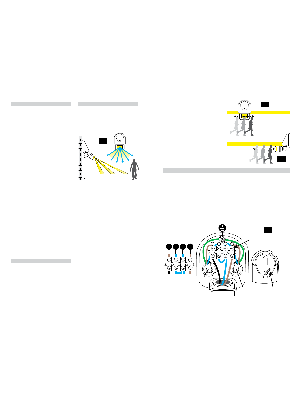
Ideally the PIR sensor should be mounted 1.8 to
2.5 metres (6 to 8ft) above the area to be scanned
(refer to Fig.1 below).
To avoid damage to the unit do not aim sensor
towards sun.
Avoid positioning the sensor unit adjacent to a
bright light source which may prevent the unit
from operating when the lux control is set to
operate in dark conditions.
Avoid nuisance false triggering by directing
sensor away from:
Trees and shrubs
Reective surfaces such as smooth white walls
Swimming pools
Heat sources such as boiler ues
The PIR sensor scanning specications
(approximately 12 metres at 110°) may vary
slightly depending on the mounting height and
location. The detection range of the unit may also
alter with temperature change.
INSTALLATION:
When installing the PIR sensor please refer to Fig. 4 below.
1. Switch o the mains before commencing installation.
2. Unscrew and remove the junction box cover.
3. Fix the unit to the mounting surface with the screw supplied, we recommend the unit should be
xed a minimum distance of 2.5 metres above the ground, noting the mounting direction on the
plastic cover. (See Fig. 1 opposite).
4. Connect the power cable and load cable to the terminal block as show in Fig. 4 below. NOTE: 3 core
6A/230VAC cable, not less than 1.5mm
2
diameter not included. The cable must pass through the
rubber grommet.
5. Close the cover and tighten the screw.
6. Restore mains power adjusting the PIR Sensor to desired working requirements.
Fig 2
Fig 3
2.5M
4M 8M 12M
110˚
Approx
Before selecting a place to install your PIR
sensor you should note that movement across
the scan area is more eective than movement
directly towards or away from the sensor
(refer to Fig.2 opposite). If movement is made
walking directly towards or away from the
sensor and not across the sensor apparent
detection range will be substantially reduced
(refer to Fig. 3 opposite).
Yellow/Green
(Power / Load)
Load
Cable
Power
Cable
Terminal
Block
L N
Brown (LOAD)
Blue (LOAD)
N
Blue (Power)
Brown (Power)
L
Black (PIR Wire)
Blue (PIR Wire)
Blue
Brown (PIR Wire)
L N N L
Front of Fitting
Screw
UP
Fig 4
Fig 1
 Loading...