

Page 1
Issue 2013
Model:
NPCH / NPCHKIT
Nema Socket Electronic Photocell & Kit Version
These instructions are provided as a guideline to assist you.
PLEASE READ THESE INSTRUCTIONS BEFORE INSTALLATION
AND RETAIN FOR FUTURE REFERENCE
FOR PRODUCT ADVICE:
• T: 01933 673 144
• F: 01933 678 083
• E: sales@eterna-lighting.co.uk
Visit our website:
www.eterna-lighting.co.uk
INSTALLATION INSTRUCTIONS
A guide for qualied electricians
EVENTUALLY, YOU MAY WANT TO
REPLACE THIS PRODUCT:
Regulations require the recycling of Waste from
Electrical and Electronic Equipment (European
“WEEE Direc tive” eective August 20 05—UK
WEEE Regulation s eective 2nd January 20 07).
Environment Agenc y Registered Producer : WEE/
GA0248Q Z.
WHEN YOUR PR ODUCT COMES TO TH E END OF
ITS LIFE OR YO U CHOOSE TO REPLACE I T, PLEASE
RECYCLE IT W HERE FACILITIES E XIST DO NOT
DISPOSE WITH HOUSEHOLD WASTE.
CLEANING:
Disconnect t he power and clean the exte rior only of
this tting wit h a moist (not wet) cloth.
Do not use any chemic al or abrasive cleaners.
IF YOU EXPERIENCE PROBLEMS:
If you believe your p roduct is defective, p lease return
it to the place where yo u bought it. Our Technical
Team will gladly advise on any Eterna Lighting
product, bu t may not be able to give specic
instructions regarding individual installations.
For breakage inf ormation visit:
www.eterna-lighting.co.uk
Pack contents:
1 x Fitting
1 x Fixing kit
(NPCHKIT only)
Page 2
READ THIS FIRST:
Check the pack and m ake sure you have all of the
parts liste d on the front of this bookle t. If not,
contact the outlet where you bought this product.
This produc t must be installed by a compet ent
person in accord ance with the current building a nd
IEE wiring regulations.
As the buyer, install er and/or user of this product it
is your own responsi bility to ensure that this tt ing
is t for the purpo se for which you have intended
it. Eterna Lightin g cannot accept any liability fo r
loss, damage or premature failure resulting from
inappropriate use.
This product is designed and constructed according
to the principles o f the appropriate British Stan dard
and is intended fo r normal domestic ser vice. Using
this tting in any oth er environments may result in
a shortened w orking life, for example w here there
is prolonged p eriods of use or higher than no rmal
ambient temper atures such as lighting public or
shared spaces or in n ursing / care home facilitie s.
This tting mus t be installed in accordance w ith the
Building Regul ations. These may be obtain ed from
HMSO or viewed and downloaded from www.odpm.
gov.uk following the lin k for Building Regulations .
Switch o the mains be fore commencing installati on
and remove the appropriate circuit fuse.
Suitable for outdoor use.
Avoid installing this u nit in direct sunlight or othe r
light sources and wh ere it will be out of reach.
This produc t is suitable for installatio n on surfaces
with normal ammability e.g. wood, plasterboard,
masonry. It is not sui table for use on highly
ammable sur faces (e.g. polystyren e, textiles).
Before makin g xing hole(s), check that there are no
obstructi ons hidden beneath the mount ing surface
such as pipes or cab les.
Do not attach to su rfaces which are damp, fresh ly
painted or other wise electricall y conductive (e.g.
metallic sur faces).
If the location o f your new tting requires th e
provision of a new el ectrical supply, the suppl y
must conform with the requirements of the Building
Regulations.
This produc t is designed for permanent co nnection
to xed wiring: this s hould be either a suitable
lighting circuit (p rotected with a 5 or 6 Amp MCB or
fuse) or a fused spu r (with a 3 Amp fuse) via a fused
connection u nit. We recommend that the suppl y
incorporates a s witch for ease of operation .
Make connecti ons to the electrical supp ly in
accordance with the f ollowing code:
(L) Live: Brown or Re d
Connect to the incoming supply live
(N) Neutral: B lue or Black
Connect to the in coming supply neutral and to th e
light/load neutral terminal.
(LO) Load Live: Brow n or Red
Connect to the li ve terminal on the light/lo ad
This tting is d ouble insulated, do not connec t any
part to eart h.
You are advised at ever y stage of your installatio n to
double-check any electrical connections you have
made. After you h ave completed your installatio n
there are elec trical tests that should b e carried out:
these tests are sp ecied in the Wiring Reg ulations
(BS7671) referre d to in the Building Regulation s.
SPECIFICATION:
Power rating: 1500VA or 5 Amp inducti ve load at
60F
Supply voltag e: 240V
Switch on/o at 30/80 lux
NPCHKIT INSTALLATION:
01) Separate the contr ol unit from the NEMA base by
twisting anti-clock wise and pulling gently.
02) Using the wa ll xing bracket as a template, mar k
and make the xing h oles.
03) Secur e the bracket in place using the 3 wall
plugs and screws su pplied. If these xings ar e
not suitable fo r your installation use suitab le
alternatives.
04) T he wall xing bracket will accept 20 m m conduit
and ttings or a p lain cable entry.
05) Ensure th at the correct rated outdo or cable is
used.
06) Ma ke connections to the NEMA so cket as detailed
above.
07) Ensure th at all connections are secu re and that
no “whiskers” or b are wires are left free f rom the
terminals.
08) Ensur e that the cork gasket is located on t he lugs
inside the wall bra cket and secure the NEMA
base socket to the b racket with the two screws
provided.
09) Re t the photocell by insertin g in the base and
twisting clo ckwise to lock. The so cket is polarised
and will only t on e way.
10) Check that yo ur light tting or other loa d has
been installed and connected correctly.
11) R estore the power and test the in stallation by
covering the control u nit (the product box is
suitable), waiting ap proximately 1 minute for the
unit to switch on and th en removing the box and
checking that th e unit switches o.
NPCH INSTALLATION:
01) The photocell may b e installed in a wall xing
bracket as detai led above.
02) It may also b e installed with a light tti ng of your
choice provide d the NEMA base is securely t ted
with suitable xings and the connections a re
made in accordance wi th the instructions above.
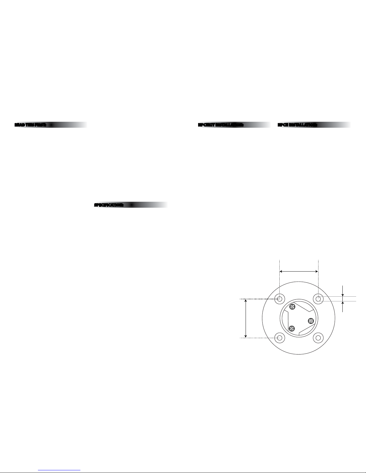
03) When xing the NEMA socket, use counte rsunk
screws to ensure ee ctive sealing of the foam
gasket on the photo cell unit.
04) Ensu re that the socket is located in a p osition
where it will not b e exposed to excessive heat
e.g. not direct ly above or in close proximity t o a
lamp or ballast.
05) Make e lectrical connect ions according to the
instructions opposite.
06) Af ter installation, conduc t tests as for installatio n
of the complete k it. In the event of damage to the
photo control unit cove r, isolate the installation
from the mains supply before unplugging.
34.5mm
36mm
4.25mm
 Loading...