

Eterna MODERNOBK, MODPIRBK, MODERNOWH, MODPIRWH Installation Instructions And Operators Manual
Page 1
Model:
MODERNOBK / MODERNOWH
MODPIRBK / MODPIRWH
6W LED Lantern / 6W LED Lantern With PIR
These instructions are provided as a guideline to assist you.
PLEASE READ THESE INSTRUCTIONS BEFORE INSTALLATION
AND RETAIN FOR FUTURE REFERENCE
INSTALLATION INSTRUCTIONS
A guide for qualied electricians
874/2012
MODELNO.
MODERNO RANGE
EVENTUALLY, YOU MAY WANT TO
REPLACE THIS PRODUCT:
Regulations require the recycling of Waste from
Electrical and Electronic Equipment (European
“WEEE Direc tive” eective August 20 05—UK
WEEE Regulation s eective 2nd January 20 07).
Environment Agenc y Registered Producer : WEE/
GA0248Q Z.
WHEN YOUR PR ODUCT COMES TO TH E END OF
ITS LIFE OR YO U CHOOSE TO REPLACE I T, PLEASE
RECYCLE IT W HERE FACILITIES E XIST DO NOT
DISPOSE WITH HOUSEHOLD WASTE.
CLEANING:
Disconnect t he power and clean the exte rior only of
this tting wit h a moist (not wet) cloth.
Do not use any chemic al or abrasive cleaners.
IF YOU EXPERIENCE PROBLEMS:
If you believe your p roduct is defective, p lease return
it to the place where yo u bought it. Our Technical
Team will gladly advise on any Eterna Lighting
product, bu t may not be able to give specic
instructions regarding individual installations.
Email: sales@eterna-lighting.co.uk / technical@eterna-lighting.co.uk
Visit our website: www.eterna-lighting.co.uk
Made in ChinaIssue 1116
PG 6 PG 1
Pack contents:
1 x LED lantern
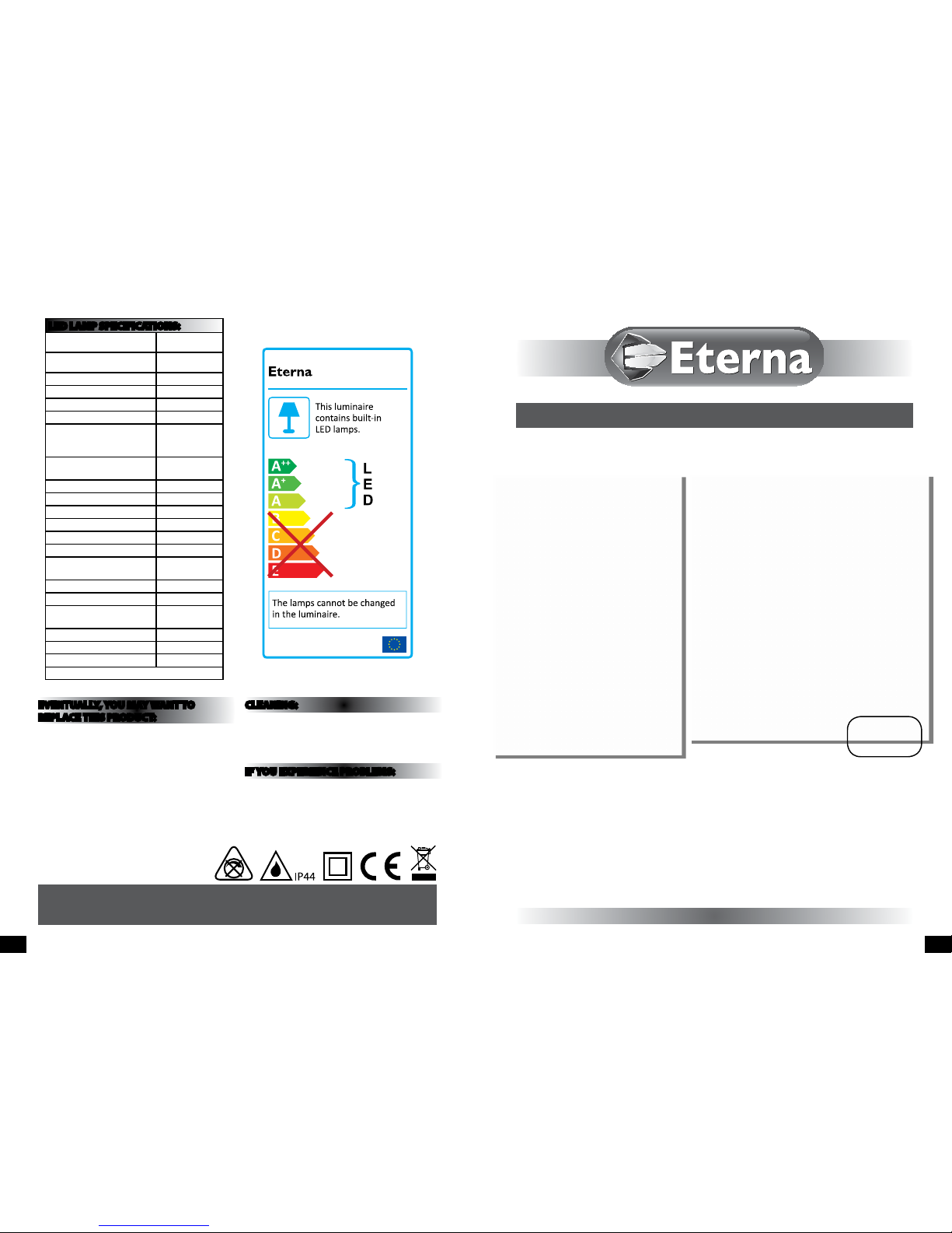
LED LAM P SPECIFICATIONS:
Lumens total ux
330 lm
Lumens 120° ux
300 lm
Rated Wattage 6W
Rated luminous ux 300 lm
Nominal life time of the lamp 35,000 hrs
Colour temperature 3100K
Number of switching cycles
before premature lamp
failure
≥15,000
Warm-up time up to 60 % of
the full light output
Instant full light
Dimmable No
LED array dimensions (Ø) 65mm
Nominal beam angle 120°
Rated power 6W
Rated lamp lifetime 35,000 hrs
Lamp power factor >0.5
Lumen maintenance factor at
end of nominal life
≥0.70
Starting time <0.1s
Colour rendering ≥80
Colour consistency
Within 6 step
Macadam ellipse
Rated peak intensity 120cd
Rated beam angle 120°
Voltage 240V
Not suitable for accent lighting
Page 2
PG 2 PG 3
READ THIS FIRST:
Check the pack and m ake sure you have all of the
parts liste d on the front of this bookle t. If not,
contact the outlet where you bought this product.
This produc t must be installed by a compet ent
person in accord ance with the current building a nd
IEE wiring regulations.
As the buyer, install er and/or user of this product it
is your own responsi bility to ensure that this tt ing
is t for the purpo se for which you have intended
it. Eterna Lightin g cannot accept any liability fo r
loss, damage or premature failure resulting from
inappropriate use.
This product is designed and constructed according
to the principles o f the appropriate British Stan dard
and is intended fo r normal domestic ser vice. Using
this tting in any oth er environments may result in
a shortened w orking life, for example w here there
is prolonged p eriods of use or higher than no rmal
ambient temper atures such as lighting public or
shared spaces.
Switch o the mains be fore commencing installati on
and remove the appro priate circuit fuse or lock o
MCB.
This unit is suitab le for outdoor use.
This produc t is suitable for installatio n on surfaces
with normal ammability e.g. wood, plasterboard
and masonry. It is not s uitable for use on highly
ammable surfaces
Before makin g xing hole(s), check that there are no
obstructi ons hidden beneath the mount ing surface
such as pipes or cab les.
Make sure that the xi ngs are strong enough to
support the co nsiderable weight of the t ting and
hold it rigidly.
The chosen loc ation of your new tting shou ld allow
for the produc t to be securely mounted. An d safely
connected to th e mains supply (lighting circuit).
When choosing th e location for your new tt ing,
ensure that the xin gs will be anchored in a solid
surface e.g. con crete, brick or a joist—do not x
directly onto panelling, cladding, plasterboard etc.
When making con nections ensure that the ter minals
are tightened se curely and that no strands of wi re
protrude. Chec k that the terminals are tightene d
onto the bared cond uctors and not onto any
insulation.
This tting is d ouble insulated; do not connec t any
part to eart h.
This produc t is not intended to be used by childr en
and persons wi th sensory, physical and/or ment al
impairments th at would prevent them from using i t
saf ely.
You are advised at ever y stage of your installatio n to
double-check any electrical connections you have
made. After you h ave completed your installatio n
there are elec trical tests that should b e carried out,
these tests are sp ecied in the current IEE wir ing and
building regulations.
INSTALLATION:
ISOLATE MAINS BEFORE
CARRYING OUT INSTALLATION
01) Undo the nuts each s ide at the front of the tting
and lift o the f ront section of the lanter n
02) Using the b ack cover of the tting as a template,
mark the locati on of the xing holes.
03) Pierce the r ubber grommet in the back of th e
tting. Make th e hole as small as possible so that
a good watert ight seal is maintained when th e
cable has been threaded through.
04) Th read the cable through the gro mmet.
05) Sec ure the tting to the wall using xings (not
supplie d).
06) Make t he connections to the termi nal block
according to the colo ur code and symbols:
LIVE - Brown or Red • NEUTRAL - Bl ue or Black
07) Conne ct the two wires from the f ront half of the
lantern to the push ter minal block in line with the
colour code and s ymbols (see g. 4 opposite).
08) Re place the front part of lanter n and secure by
tightening the t wo nuts making sure you have a
rubber sealin g washer under both nuts.
09) Res tore power.
10) Switch on and product should function.
SPECIFICATIONS:
• Det ection range: Approx. 120° (hor izontal), Max. 8
metres.
• Duration time: f rom 5 sec - 5 mins. (adjustable).
• No over ride facility.
• LUX - adjustable.
LAMP REPLACEMENT:
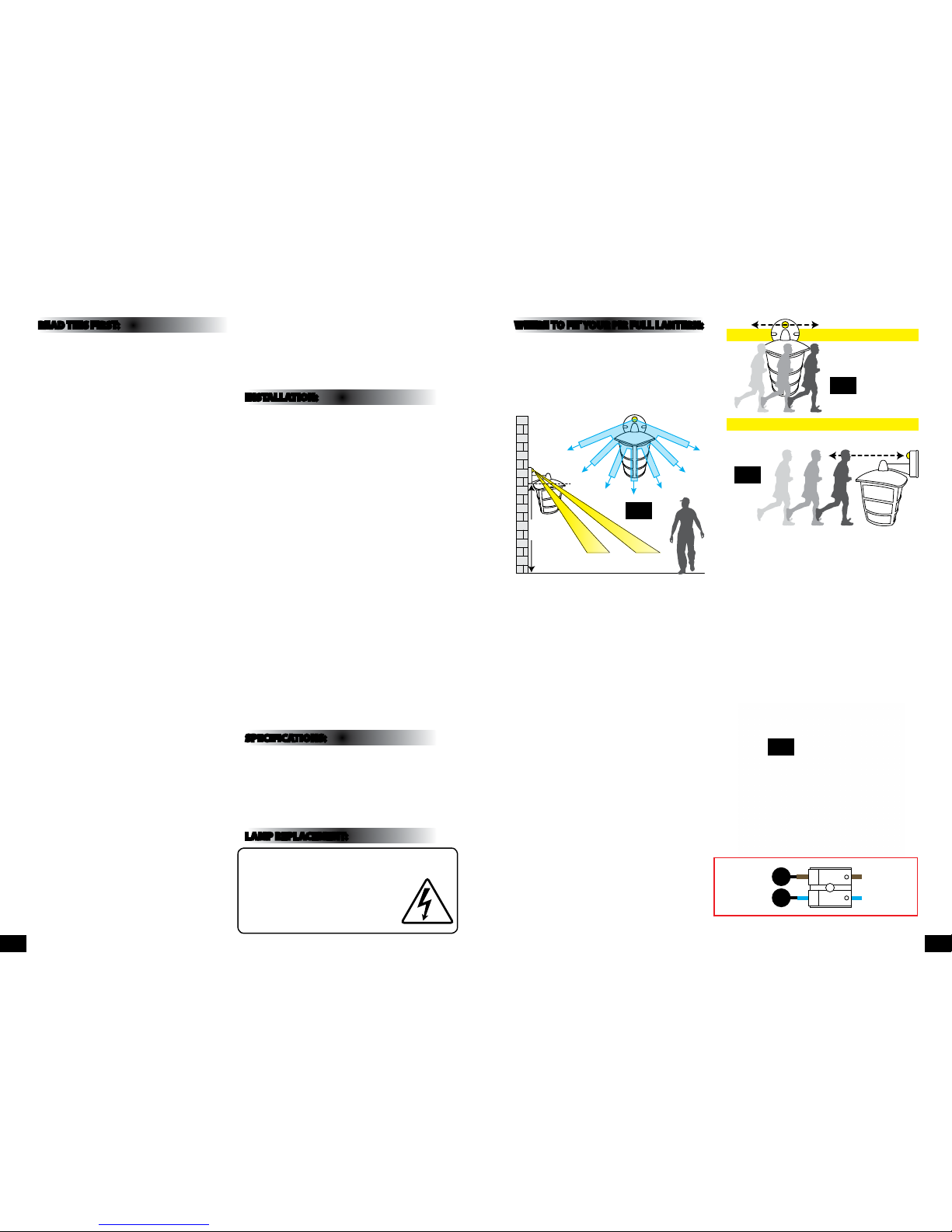
WHERE TO F IT YOUR PIR FU LL LANTERN:
To achieve best results we su ggest you take the
following points into consideration:
Do not mount on a sur face that has vibration.
Ideally the PIR lante rn should be mounted 1.8 to 2.5
metres (6 to 8ft) ab ove the area to be scanned (refer
to Fig. 1 below).
To avoid damage to the unit do not ai m sensor
towards the sun.
Avoid positioning th e sensor unit adjacent to a
bright light source w hich may prevent the unit from
operating whe n the lux control is set to operate i n
dark conditions.
Avoid nuisance false t riggering by directing s ensor
away from:
Trees and shrubs
Reective su rfaces such as smooth white w alls
Swimming pools
Heat sources such as b oiler ues
The PIR sensor sc anning specications
(approximately 8 met res at 120°) may vary slightly
depending on the mounting height and location.
The detecti on range of the unit may also alter
with temperatu re change. Before selec ting a place
to install your PIR lant ern you should note that
movement across the s can area is more eective
than movement dire ctly towards or away from the
sensor (refer to Fig. 2 a bove).
If movement is made w alking directly towards o r
away from the senso r and not across the apparent
detection r ange will be substantially re duced (refer
to Fig. 3 above).
1.8-
2.5M
4M 8M
120˚
Approx
Fig 1
EFFECTIVE:
Movement
across scan area
LESS EFFECTIVE:
Movement directly in front of
scan area
Fig 2
Fig 3
L N
Blue
(Power Cable)
Brown
(Power Cable)
Blue
(Power Cable)
Brown
(Power Cable)
Fig 4
The light source cont ained in this luminaire
shall only be rep laced by the manufacturer,
service age nt or a similar qualied pers on.
CAUTION, RISK OF ELECTRIC SHOCK.
The light source is designed to last the lifetime of the
luminaire.
Page 3

UNDERSTANDING THE CONTROLS FOR PIR MODEL:
ADJUSTING THE DURATION TIME:
The length of tim e that the light remains switche d on after activation ca n be adjusted from 5 seconds to
5minutes. Rotatin g the TIME screw (+) to (-) will reduce the time duratio n.
NOTE: once the light has bee n triggered by the PIR sensor any su bsequent detection wi ll start the timed
period again from the beginning.
ADJUSTING THE LUX CONTROL LEVEL:
The lux control mo dule has a built-in sensing devi ce (photocell) that detect s daylight and darkness. Th e ()
position deno tes that the bulkhead light can wo rk at day and night, and the () position w ill only work at night.
You can set to operate the li ght at the desired level by adjusti ng the LUX screw.
SETTING THE CONTROLS:
Turn the LUX control knob to light () positi on, at this stage ensure that the tim e control screw is set at
minimum duration t ime (-) position. The bulkhea d light will now switch on and remain o n for about 5 seconds.
Direct the se nsor toward the desired area to be s canned. Adjust time control to r equired setting.
To set the LUX level at which the lamp w ill automatically switch “on” at night , turn the LUX control screw from
daylight to night (). If the la mp is required to switch on earlie r, e. g. dusk, wait for the desired env ironment
light level, then sl owly turn the LUX control screw towards t he daylight () while someone walk s across the
centre of the area to be d etected. When the lamp s witches on, stop adjusting.
TROUBLESHOOTING AND USER HINTS:
Note: all passive infra re d detectors are more se nsitive in cold and dry weather th an warm and wet weather.
PROBLEM POSSIBLE CAUSE SUGGESTED REMEDY
Light does not switch on
when there is movement
in the detection area.
1. No mains voltage Check all connections, and MCB Fuses / switches
2. Nearby lighting is too bright Relocate the unit
3. Wired incorrectly
Check wiring and conrm its wired as per the
wiring diagram
Light switches on for no
apparent reason (false
trigger)
1. Heat sources such as air-con, vents, heaters, ues,
other outside lighting, moving cars trees or shrubs
are activating sensor
Relocate tting
2. Animals / birds activating sensor Relocate tting
3. I nterference from on/o switching of electric fans
or lights on the same circuit as your tting.
(This problem does not always occur but a faulty
switch may cause the tting to switch on)
Should the false triggering become, troublesome,
consider:
(a) Replacing a faulty switch
(b) Connecting the tting to a separate circuit (in
most cases where one or more of the above
suggestions have been carried out, false
triggering has been reduced)
4. Reec tion from swimming pool, or reective
surface such as smooth white walls
Relocate tting
Light remains on Continuously false triggered Relocate tting
Light remains on at
nighttime
Possible heat source in detection zone
Cover PIR sensor lens with a thick cloth, if the
light turns o check detection area for heat or
reective source
When setting the lux
controls in daylight
the detection distance
becomes shorter
Interference by sunlight Re-test at night
PG 4 PG 5
TIME LUX
 Loading...