

Page 1
Issue 2014
Model:
ML5040
Mirror Light With Dual Voltage Shaver Socket
These instructions are provided as a guideline to assist you.
PLEASE READ THESE INSTRUCTIONS BEFORE INSTALLATION
AND RETAIN FOR FUTURE REFERENCE
Pack contents:
1 x Mirror light
2 x 15W G13 T8 450mm tubes
1 x Fixing kit
FOR PRODUCT ADVICE:
• T: 01933 673 144
• F: 01933 678 083
• E: sales@eterna-lighting.co.uk
Visit our website:
www.eterna-lighting.co.uk
INSTALLATION INSTRUCTIONS
A guide for qualied electricians
874/2012
A
MODELNO.
ML5040
MODELNO.
A
++
XXX kWh/1000h
18.57
ML5040
A
EVENTUALLY, YOU MAY WANT TO
REPLACE THIS PRODUCT:
Regulations require the recycling of Waste from
Electrical and Electronic Equipment (European
“WEEE Direc tive” eective August 20 05—UK
WEEE Regulation s eective 2nd January 20 07).
Environment Agenc y Registered Producer : WEE/
GA0248Q Z.
WHEN YOUR PR ODUCT COMES TO TH E END OF
ITS LIFE OR YO U CHOOSE TO REPLACE I T, PLEASE
RECYCLE IT W HERE FACILITIES E XIST DO NOT
DISPOSE WITH HOUSEHOLD WASTE.
CLEANING:
Clean this light t ting only with a soft dr y cloth.
Do not use any chemic al or abrasive cleaners.
IF YOU EXPERIENCE PROBLEMS:
If you believe your p roduct is defective, p lease return
it to the place where yo u bought it. Our Technical
Team will gladly advise on any Eterna Lighting
product, bu t may not be able to give specic
instructions regarding individual installations.
For breakage inf ormation visit:
www.eterna-lighting.co.uk
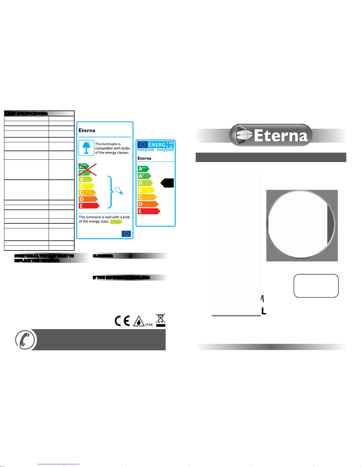
LAMP SPECIFICATIONS:
Nominal Wattage 15W
Rated Wattage 15W
Average lifetime hours 15,000 hrs
Nominal useful luminous ux
1010 lm
Rated luminous ux 1010 lm
Luminous ecacy (Lm/W) in
50Hz operation
67
Luminous ecacy (Lm/W) in
HF operation
67
Rated lamp Lumen
maintenance
2000hrs: 95%
4000 hrs: 92%
6000 hrs: 91%
8000 hrs: 91%
12000 hrs: 85%
Rated survival factors
2000hrs: 99%
4000 hrs: 97%
6000 hrs: 95%
8000 hrs: 91%
12000 hrs: 85%
Lamp dimensions (mm) 450mm
Cap type G13
Lamp Mercury content to an
accuracy of 0.1mg
≤2.5mg
Colour rendering index Ra ≥80
Colour temperature 3000K
Ambient temperature required
to achieve maximum luminous
ux
25°C
Dimmable No
Ballast EEI A2
Page 2
READ THIS FIRST:
Check the pack and m ake sure you have all of the
parts liste d on the front of this bookle t. If not,
contact the outlet where you bought this product.
This produc t contains glass, care must be take n when
assembling, t ting or handling to prevent per sonal
injury or damag e to the product.
This light ttin g must be installed in accorda nce
with the Building R egulations making refe rence to
the current editi on of the IEE Wiring Regulati ons
(BS7671). The Building Re gulations may be obtained
from OPSI (Oce of Pub lic Sector Information) or
viewed and downloaded from www.communities.
gov.uk following the lin k for Building Regulations .
Switch o the mains be fore commencing installati on
and remove the appropriate circuit fuse.
This tting cont ains an isolating transfor mer rated
at 20W maximum and is on ly intended for use with
electric sh avers. It is possible to connec t other
devices to the socke t outlet such as chargers for
electric to othbrushes provided they a re tted
with the correc t plug. Use of the socket to power
equipment requiring greater than 20W will cause
the transform er to overheat and/or stop workin g
altogether. Please re fer to the manufacturer s
instructio ns supplied with your applian ce to
determine whe ther it is suitable for use in the
location whe re you have installed your shaver light
and that the power con sumption is less than 20W.
The switch in your tting turns the light on and o.
The sockets are permanently live.
When using the shave r socket, ensure that the
correct soc ket is used according to the workin g
voltage of your ap pliance. Connecting your
appliance to the wro ng socket could cause
permanent dam age to your appliance, your ttin g
or both.
Suitable for indoor use only.
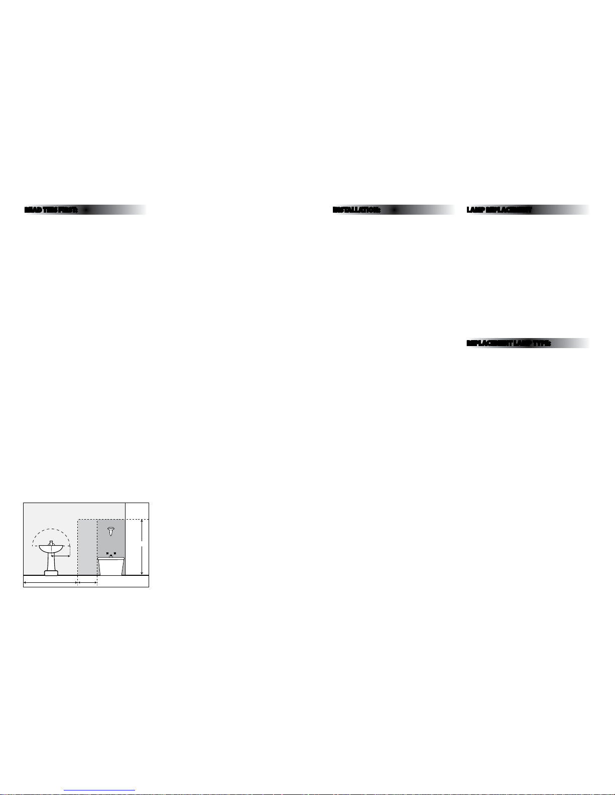
This tting is su itable for use in bathrooms in Zo ne 2
or outside. Thi s tting must not be install ed in zones
0, 1 see diagram be low:
This produc t is suitable for installatio n on surfaces
with normal amm ability (indicated by the “ F” in a
triangle) e.g. wood , plasterboard, masonr y. It is not
suitable for us e on highly ammable surfa ces
(e.g. polysty rene, textiles).
Before makin g xing hole(s), check that there are no
obstructi ons hidden beneath the mount ing surface
such as pipes or cab les.
The chosen loc ation of your new tting shou ld allow
for the produc t to be securely mounted and s afely
connected to th e mains supply (lighting circuit).
The tting, e specially the shaver socket, s hould be
placed where it c annot be splashed.
This produc t is designed for permanent co nnection
to xed wiring: this s hould be either a suitable
lighting circuit (p rotected with a 5 or 6 Amp MCB or
fuse) or a fused spu r (with a 3 Amp fuse) via a fused
connection u nit. We recommend that the suppl y
incorporates a s witch for ease of operation .
Make connecti ons to the electrical supp ly in
accordance with the f ollowing code:
Live - Brown or Red
Neutral - Blue or B lack
Earth - Gree n and Yellow
This produc t must be connected to Ear th.
When making con nections, ensure that the te rminals
are tightened se curely and that no strands of wi re
protrude. Chec k that the terminals are tightene d
onto the bared cond uctors and not onto any
insulation. Wrap lo ose terminal blocks wel l with
insulating tape.
Disconnect t he tting from the elec trical supply
before ash or hi gh voltage testing.
Suitable for indoor use only.
If the location o f your new tting requires th e
provision of a new el ectrical supply, the suppl y
must conform with the requirements of the Building
Regulations mak ing reference to the current e dition
of the IEE Wiring Re gulations (BS7671).
You are advised at ever y stage of your installatio n to
double-check any electrical connections you have
made. After you h ave completed your installatio n
there are elec trical tests that should b e carried out:
these tests are sp ecied in the Wiring Reg ulations
(BS7671) referred to in th e Building Regulations.
INSTALLATION:
01. Choose the loc ation for your mirror light
complying with the conditions listed opposite.
02. Lay the t ting at and remove the four scr ews
that retain the mir ror (two each side).
03. Lift the mirr or o of the tting and store sa fely.
04. Usin g the metal case as a template, mark t he
position of the xing holes. Laying a spirit l evel
across the top of the m etal case will help ensure
that your mirror is ins talled level.
05. Prepare t he xing holes as appropri ate to your
mounting surf ace.
06. Pie rce the rubber grommet in the ca ble entry
hole that you intend to u se. Do not make the
hole too large, th e rubber grommet must make a
watertight seal around the supply cable.
07. Thread the supply ca ble through the pierced
grommet.
08. Se cure the metal case to the wall us ing the
xings supplie d. If the xings supplied ar e not
appropriate to your installation, use suitable
alternatives.
09. Remove th e plastic box covering the mains
terminals and shaver socket transformer.
10. Make the ele ctrical connectio ns according to the
colour code opposite.
11. Re-t the plastic cove r over the terminals and
transformer.
12. Fit the uoresce nt tubes by slotting into the
lampholders and turning through approx 90° or
until they click softly into position.
13. Check that the so ft gasket is correctly p ositioned
around the facin g edge of the metal case.
14. Replace the mi rror and secure in position u sing
the four screws removed previously. Press rmly
on the mirror to ensur e a tight t against the
gasket before tightening screws.
15. Restore the power and sw itch on.
LAMP REPLACEMENT
1. Switch o the electr icity at the mains.
2. Remo ve the four retaining screws (tw o each side)
and lift o the m irror.
3. Remove an d replace tube(s). Fit the uorescent
tubes by slotti ng into the lampholders and tu rning
through approx 90 ° or until they click softly i nto
position maki ng sure that the tube is of the same
type and wat tage as stated on the relam ping label.
4. Check t hat the soft gasket is correc tly positioned
around the facin g edge of the metal case.
5. Repla ce the mirror and secure in posit ion using the
four screws remove d previously. Press rmly on the
mirror to ensure a tigh t t against the gasket and
tighten the screws.
6. Restore the p ower and switch on.
REPLACEMENT LAMP TYPE:
Requires 2 x 15W G13 T8 450mm uorescent tubes
3000K (included).
Fitting is rated a t 15W max (per lamp holder).
225cm
60cm240cm
60cm
radius
from tap
ZONE 1
ZONE 0
ZONE 2
ZONE 2
Bathroom Zones Diagram
 Loading...