

Page 1

PAGE 6 PAGE 1
Pack Contents
Heat Detecto r x 1
Mounting Plate x 1
Mains Connect or x 1
9V Battery x 1
Fixing Kit x 1
INSTALLATION INSTRUCTIONS
A guide for qualied electricians
Model:
MHDB
Mains Heat Detector With Battery Back-Up
These instructions are provided as a guideline to assist you.
PLEASE READ THESE INSTRUCTIONS BEFORE INSTALLATION
AND RETAIN FOR FUTURE REFERENCE
SPECIFICATIONS:
Power Source: 220-240Vac~ 50-60Hz with 9V
battery back-up.
Battery B ack-Up: 9Vdc Alkaline or Carbo n Zinc
battery :EVER READY PP3S
DURACELL MN1604 9V.
Battery B ack-Up Life: In the event of a break in the
mains supply the b attery will
give detector operation for 1
year minimum.
Operating Cur rent: <20mA operation (in a larm),
15A in standby mode .
Alarm Sound Leve l: 85 Decibels at 3 me tres.
Hush Facility: Mutes alarm for 10 minutes, i f
heat increases during this time
the alarm will be
re-triggered.
Sensitivity: 58°C xed temperature only.
Maximum ambi ent: 45°C
Interconnec t Facility: 40 x smoke / heat detector s -
over 150 metre maximum.
Recommended coverage: 200m
2
Recommended spacing: 13.5M
Maximum dist ance from wall: 7.5M
BATTERY REPLACEMENT:
1. Switch o the elec tricity at the mains.
2. Remove the locki ng tabs from the side of the a larm,
twist the ala rm anti clockwise and p ull away from the
base.
3. Remove the powe r connector.
4. Remove and rep lace the battery.
5. Replace the pow er connector.
6. Fit the alarm back onto t he base and twist clo ckwise,
ret the locking tabs.
7. Restore the power at the mai ns.
8. Check the alarm is fu nctioning by pushing t he test
button.
CLEANING:
Clean this alarm o nly with a soft dry cl oth.
Periodicall y vacuum around the alarm to d islodge and
remove dust par ticles that may have gathere d.
Do not use any chemi cal or abrasive cleaner s
EVENTUALLY, YOU MAY WANT TO
REPLACE THIS PRODUCT:
Regulations require the recycling of Waste from
Electrical and Electronic Equipment (European “WEEE
Directive” eective August 2005—UK WEEE Regulations
eective 2nd January 2007). Environment Agency
Registered Producer: WEE/GA0248QZ.
WHEN YOUR PR ODUCT COMES TO T HE END OF ITS
LIFE OR YOU CH OOSE TO REPLACE IT, PLEA SE RECYCLE
IT WHERE FACI LITIES EXIS T DO NOT DISPOSE WI TH
HOUSEHOLD WASTE.
IF YOU EXPERIENCE PROBLEMS:
If you believe you r product is defec tive, please return it
to the place wher e you bought it. Our Technical Team
will gladly adv ise on any Eterna Lighting pr oduct, but
may not be able to gi ve specic instruct ions regarding
individual installations.
Email: sales@eterna-lighting.co.uk / technical@eterna-lighting.co.uk
Visit our website: www.eterna-lighting.co.uk
Made in ChinaIssue 0616
Page 2
READ THIS FIRST:
Check the pack and make sure you have all of the parts listed
on the front of this booklet. If not, contact the outlet where
you bought this product.
This Heat Alarm must be installed by a competent person
in accordance with the building regulations and IEE wiring
regulations.
Switch o the mains before commencing installation and
remove the appropriate circuit fuse.
This heat alarm is suitable for indoor use only.
This product is suitable for use in living areas (not for areas
constantly subject to moisture).
This product is suitable for installation on surfaces with normal
ammability e.g. wood, plasterboard, and masonry.
Before making xing hole(s), check that there are no
obstructions hidden beneath the mounting surface such as
pipes or cables.
The chosen location of your new heat alarm should allow for
it to be securely mounted (e.g. to a ceiling joist) and safely
connected to the mains supply.
Do not attach to surfaces which are damp, freshly painted or
otherwise electrically conductive (e.g. metallic surfaces).
This product is designed for permanent connection to xed
wiring: this should be a suitable circuit (protected with the
appropriate MCB or fuse)
This alarm is double insulated; do not connect any part to
earth.
Cable of at least 0.75mm
2
cross-sectional area must be used to
connect to the supply and between alarms.
You are advised at every stage of your installation to doublecheck any electrical connections you have made. After you
have completed your installation there are electrical tests that
should be carried out: these tests are specied in the Wiring
Regulations (BS7671) referred to in the Building Regulations
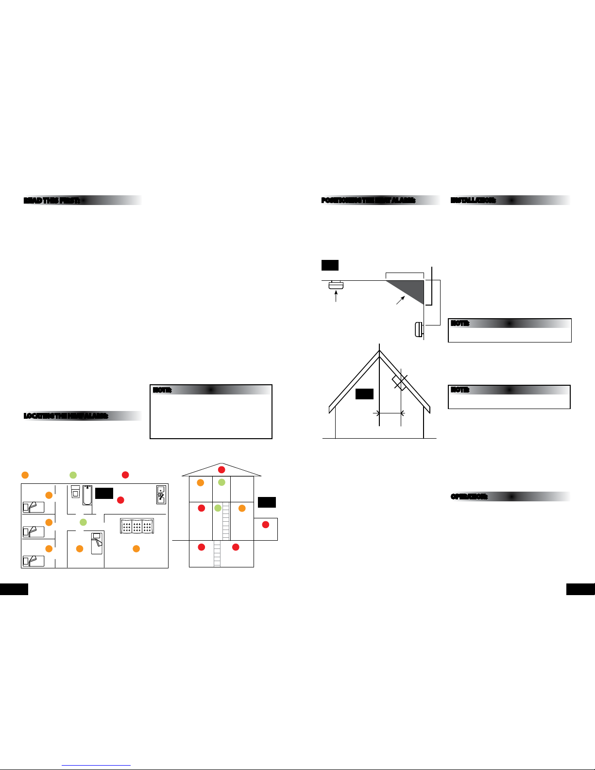
LOCATING THE HEAT ALARM:
Heat alarms are only intended to be supplementary to smoke
alarms and should only be placed in areas where smoke
alarms cannot be used.
This heat alarm is a multiple station heat alarm and can be
connected to other alarms of the same make and type.
This interconnect feature allows up to 40 heat alarms and/
or smoke alarms to be connected together using the single
yellow wire and thus allowing all alarms to sound when only
one is activated.
This heat alarm cannot be connected to any other device such
as re alarm panel.
This heat alarm gives a re warning when the temperature at
the unit reaches 58°C. It is ideal for: kitchens, garages, cellars,
boiler rooms, attics, and other areas where there are normally
high levels of fumes, smoke or dust which preclude the use of
smoke alarms due to the risk of false alarms.
All heat alarms and smoke alarms should be interconnected
to ensure the early warning will be heard particularly by
somebody sleeping. A properly designed early warning re
system ensures the alarm is given before the escape route
becomes blocked with smoke. Therefore there must be smoke
alarms along the escape routes as heat alarms would not
give sucient warning, however a re in a closed room (e.g.
kitchen) adjoining the escape route can eventually cause the
corridor to become smoked-logged due to smoke leaking out
from around the door before adequate warning can be given
by detectors in the corridor. A heat alarm in the closed room
may give early warning of re in that room.
If your dwelling is on a single storey, for minimum protection
you should t a smoke alarm in a corridor or hallway between
the sleeping and living areas. Place it as near to living areas as
possible and ensure the audible alarm can be heard when the
bedrooms are occupied. See g. 1 below for examples.
If your dwelling is multi-storey, for minimum protection one
smoke alarm should be tted at the bottom of the staircase
with further alarms tted on each upstairs landing. This
includes basements but excludes crawl spaces and unnished
attics. See g 2. below for examples.
NOTE:
For maximum protection, smoke alarms should be tted in
every room (except kitchen, bathroom and garage).
Fit heat alarms in kitchens, garages, boiler rooms etc. within
5.3m (17ft) of potential re sources.
Do not t a heat alarm in a bathroom, shower room or
other room where the unit may be triggered by steam or
condensation.
POSITIONING THE HEAT ALARM:
As heat rises its advisable to mount the alarm on a ceiling in a
central position. Avoid areas where there is no air circulation
e.g. corners of rooms and keep away from anything that might
obstruct the free ow of air. If wall mounting, do not mount
tight into corners, on sloping ceilings, mount the detector at
least 900mm from the apex measured horizontally see g 3
and 4 below:
Areas to be avoided include the following:
Locations where the ambient temperature may fall below 4°C
or rise above 40°C.
Humid areas e.g. bathrooms, shower rooms where the relative
humidity may exceed 90%.
Adjacent to or directly above hot objects such as radiators or
wall vents that can aect the direction of air currents
In very dusty or dirty environments such as workshops.
Near a decorative object, door, light tting, window moulding
etc that may prevent heat from entering the alarm
Locate the unit at least 1.5cm and route wiring at least 1m
away from uorescent light ttings as electrical noises and/or
ickering may aect the unit. Do not wire the detector into the
same circuit as a dimmer or uorescent light tting.
Do not locate in insect infested areas, insects and
contamination on the heat alarm sensor can increase its
response time.
INSTALLATION:
01) Remove the mounting plate from the alarm by turning it
anti clockwise.
02) Use the mounting plate as a template and mark the
position of the xing holes.
03) Place the base plate over the xing holes and secure by
using the wall plugs and screws supplied.
04) Connect the power connector to the incoming mains
supply: blue wire neutral, brown wire live and yellow wire
for interconnecting. If multiple heat alarms are not to
be interconnected, isolate the yellow wire in a separate
terminal block.
05) When the heat alarms are to be interconnected, connect
all of the yellow wires together.
06) If the heat alarms are to be locked into position remove
one of the tamper-proof tabs from the mounting plate and
retain for use later.
07) Insert the 9v battery into the heat alarm noting the
polarity of the connections.
NOTE:
For safety of end user the heat alarm cannot be tted without
a battery.
08) Before assembly to the base plate, test the correct
operation of the heat detector (operating from the battery
only) by pressing the test button on the front of the
detector. The unit should emit a loud pulsating alarm.
09) Connect the power connector into the socket on the rear
of the heat detector.
NOTE:
This is a polarized connector and can only be plugged in one
way.
10) Assemble the detector onto the base plate by aligning
the two projections on to the base plate with two
corresponding sockets in the detector. Lock in to position
by turning clockwise.
11) Insert the tamper-proof tab into the position provided
between the base plate and the detector unit. Once tted
the detector can only be removed from the base plate by
rst removing the tab by gently prising it out with a screw
driver. See pg 4 for diagram guide.
12) Replace circuit fuse and restore the power.
13) Test the correct operation of the heat detector by pressing
the test button on the front of the detector. The alarm
should emit a loud pulsating alarm.
OPERATION:
Once your heat alarm has been installed, a small green
indicator light (LED) should be visible through the detector
grill indicating that the AC supply is healthy. A red indicator
light (LED) should ash once a minute to indicate battery is
healthy.
When the heat alarm senses a temperature above 58°C (plus or
minus a few degrees) the unit will emit a loud (85db) pulsating
alarm until the temperature drops below 58°C. During the
alarm activation the red indicator light will ash quickly.
PAGE 3PAGE 2
900mm
Bedroom
Smoke detector
optional place
Prefered place for
a smoke detector
Prefered place
for a heat detector
Placement Key:
Bedroom
Bedroom
Bedroom
Hall
Living Room
Kitchen
Bathroom
Bedroom
Attic
Kitchen
Boiler RoomBasement
Landing Bathroom
Living
Room
Garage
Hall
O
O
O
O
O
O O O
S
P
S
S
H
H
H
H
HH
H
Fig. 1
Fig. 2
Fig 3
Ceiling
1 metre
Best in
centre
of
room
Dead air space
- do not mount
in this area
15cm mim
30cm max
Fig. 4
Page 3

TESTING YOUR HEAT ALARM:
After installation and after reoccupation of the dwelling after a
vacation etc; check all alarms for correct operation.
It is recommended that you test your heat alarm once a week
to ensure the detector is working correctly.
Push and hold the test button for approximately 3 seconds. A
loud pulsating alarm should sound and a red ashing indicator
light (LED) can be seen to indicate that the unit is functioning
correctly.
NOTE:
For multiple interconnected heat alarms; test each alarm in
turn checking also that the alarm is triggered on all other heat
alarms.
MAINTAING YOUR HEAT ALARM:
If the heat detector emits a short “beep” once a minute then
the battery is at the end of its life and should be replaced
immediately. This low voltage warning will continue to sound
for at least 7 days.
WARNING:
The use of batteries other than those recommended on the
back of the heat alarm may be detrimental to its operation.
Clean your heat alarm regularly to prevent dust build up
this can be done using a vacuum cleaner with the brush
attachment. Clean gently around the front grille sections and
sides.
IMPORTANT:
If there is any question as to the cause of an alarm it
should be assumed that the alarm is due to an actual re
and the dwelling should be evacuated immediately.
IN THE EVENT OF A FIRE:
• Leave the building as quickly as possible.
• Check room doors for smoke or heat do not open a hot
door. Use an alternative escape route, crawl along the oor if
possible breathe through a wet cloth or hold your breath. Do
not stop to collect anything.
• Meet at a pre-arranged meeting place outside the dwelling
and check everybody is there.
• Call the Fire Brigade immediately from outside the building.
The brigade should be summoned regardless of the size
of the re and regardless of whether there is a facility for
transmission of alarms to a remote manned centre.
• Do not go back inside a burning building wait for the Fire
Brigade to arrive.
IMPORTANT SAFE GUARDS:
Installation of your heat alarm is only one step in your safety
plan. Other important steps should be taken to further
improve your safety:
• Install this heat alarm properly by following this instruction
leaet.
• Test your heat alarm weekly.
• Replace the battery immediately once depleted.
• Do not smoke in bed.
• Keep matches and lighters away from children.
• Store ammable materials in a proper manner and never use
them near naked ames or sparks.
• Maintain emergency equipment such as re extinguishers,
escape ladders etc and ensure all occupants know how to
use them correctly.
• Plan an escape route(s) from your building in advance and
ensure all occupants are aware of them. Re-enforce this
awareness periodically throughout the year.
• Make sure that the escape routes remain free of any
obstructions.
THIS PRODUCT IS SEALED AND CANNOT
BE REPAIRED.
COMMON CAUSES AND AVOIDING FALSE
ALARMS:
The heart alarm may be triggered by steam, condensation or
heat. Keep away from these sources to avoid nuisance alarms.
(See areas to be avoided in the positioning the heat alarm
section on page 2 and 3).
ACTION IN THE EVENT OF A FALSE
ALARM:
Check the house carefully in case there is a small re
smouldering somewhere.
Check whether the alarm was triggered by a source of heat.
You should get your family into a safe place before your
investigation
If there are frequent nuisance false alarms it may be necessary
to re- locate the device. If for some reason the unit continues
to give false alarm it can be silenced by disconnecting the
mains power and removing the unit. If cleaning the alarm
does not correct the problem it can be returned to the place
where you bought it.
PAGE 5PAGE 4
FITTING TAMPERPROOF TABS:
To use the locking tab, remove one of them from the mounting plate and insert into the assembled housing as shown below:
WIRING AND INTERCONNECT FACILITY:
Interconnection facility for up to 40 alarms, using only 3 wires, including AC power. When one alarm sounds, all properly
inter-connected alarms will sound.
See below diagram for wiring instructions:
Step 1 Unclip tab from
base unit
Note: If needed,
use a screwdriver to
remove the locking
tab from the tting
Fig. 5
Fig. 6
Step 2 Insert tab in to
the gap on the side of
the base unit
Live (Brown) 220-240V ac
Interconnect (Yellow) (Isolate when not req)
Neutral (Blue)
Live (Brown) 220-240V ac
Interconnect (Yellow)
Neutral (Blue)
 Loading...