

Eterna LEDTWNSPOT Installation Instructions Manual
EVENTUALLY, YOU MAY WANT TO
REPLACE THIS PRODUCT:
Regulations require the recycling of Waste from
Electrical and Electronic Equipment (European “WEEE
Directive” eective August 2005—UK WEEE Regulations
eective 2nd January 2007). Environment Agency
Registered Producer: WEE/GA0248QZ.
WHEN YOUR PR ODUCT COMES TO T HE END OF ITS
LIFE OR YOU CH OOSE TO REPLACE IT, PLEA SE RECYCLE
IT WHERE FACI LITIES EXIS T DO NOT DISPOSE WI TH
HOUSEHOLD WASTE.
CLEANING:
Clean this tti ng only with a soft dr y cloth.
Do not use any chemi cal or abrasive cleaner s.
IF YOU EXPERIENCE PROBLEMS:
If you believe you r product is defec tive, please return it
to the place wher e you bought it. Our Technical Team
will gladly adv ise on any Eterna Lighting pr oduct, but
may not be able to gi ve specic instruct ions regarding
individual installations.
For breakage in formation visit:
www.eterna-lighting.co.uk
Model:
LEDTWNSPOT
IP65 LED Emergency Twinspot Fitting
These instructions are provided as a guideline to assist you.
PLEASE READ THESE INSTRUCTIONS BEFORE INSTALLATION
AND RETAIN FOR FUTURE REFERENCE
INSTALLATION INSTRUCTIONS
A guide for qualied electricians
3 HOURS DURATION IN EMERGENCY MODE
Pack contents:
1 x LED tting
1 x Maintenance chec k record
Email: sales@eterna-lighting.co.uk / technical@eterna-lighting.co.uk
Visit our website: www.eterna-lighting.co.uk
Made in ChinaIssue 1015
READ THIS FIRST:
This produ ct must be install ed by a competent
person in accordance with the current building
and IEE wiring regulations.
As the buyer, install er and/or user of this product it
is your own responsi bility to ensure that this tt ing
is t for the purpo se for which you have intended
it. Eterna Lightin g cannot accept any liability fo r
loss, damage or premature failure resulting from
inappropriate use.
Switch o the mains be fore commencing installati on
and remove the appro priate circuit fuse or lock o
MCB.
The batteri es supplied with this ttin g are
consumable par ts and therefore may be out side of
any warranty oered.
This unit is suitable for indoor and outdoor use only.
Before makin g xing hole(s), check that there are no
obstructi ons hidden beneath the mount ing surface
such as pipes or cab les.
Ensure that the tt ing will be accessible after
installation fo r maintenance and self testing .
When making con nections ensure that the ter minals
are tightened se curely and that no strands of wi re
protrude. Chec k that the terminals are tightene d
onto the bared cond uctors and not onto any
insulation.
This produc t must be connected to ear th
termination.
You are advised at ever y stage of your installatio n to
double-check any electrical connections you have
made. After you h ave completed your installatio n
there are elec trical tests that should b e carried out,
these tests are sp ecied in the current IEE wir ing and
building regulations.
LAMP REPLACEMENT:
This luminaire has sealed LED lamps and is
maintenance free , no lamp replacement is require d.
BATTERY REPLACEMENT:
If after routi ne operation check, th e lamp does not
remain lit for the th ree hour period, a new bat tery
pack may be require d.
01) Switch o the elec tricity at the mains and allow
batteries to f ully discharge then reconne ct to
supply and allow charging for 24 hours.
02) Test again for 3 ho urs, if light does not remain li t,
then change the ba ttery pack as follows:
03) Remove fo ur screws and lift o front cove r plate.
04) Unp lug the battery lead.
05) Rem ove the two screws from the clamp ing
bracket that secu re the battery pack in pl ace and
lift the bat tery pack out of the tti ng.
06) Write c urrent date on the new batter y pack and
t new batter y pack securing in place with t he
screws, nuts and washers previously removed.
07) Reconnect b attery.
08) Re place and x front cover plate.
09) Res tore power and allow charging fo r 24 hours.
10) Perfo rm full operation check an d update test
record.
REPLACEMENT BATTERY TYPE:
3.6V 6Ah NI-CD b atteries.
INDUSTRIAL BATTERIES:
Within cert ain products Eterna L ighting Ltd places lead
acid, lithium io n, nickel cadmium & nickel m etal hydride
batteries on the market. Industrial batteries are subject
to waste regulat ion under the Waste Batte ries and
Accumulators Regulations 2009 and should be disposed
of responsibl y. Purchasers may be able to disp ose of
their waste industrial batteries locally via legitimate
licensed trade waste contractors. Eterna is obliged
to take back, f ree of charge and within a rea sonable
time, waste indu strial batteries of t he same chemistry
supplied to a Purch aser, for treatment and rec ycling
and is required t o do this in any calendar year ne w
industrial ba tteries are placed on th e market. In certain
circumstances, this may include batteries not originally
supplied by Eterna. If any Purchaser requires Eterna
to take back Indus trial batteries, th ey should write to
the Operatio ns Director, Eterna Lighti ng Ltd, Huxley
Close, NN8 6AB, wh o will then advise on the n ecessary
arrangements for the receipt, proper treatment and
recycling of, the waste industrial batteries.
INSTALLATION:
Choose the loc ation of your new tting givin g
consideration to a ll of the points listed above.
01) Remove four screw s and lift o front cover.
02) Make cab le entry hole using an appro priate
hole cutter an d drill out xing points in ba ck of
housing.
03) Using the b ack of the tting as a template, mar k
and drill out xing holes on your mounting
surface.
04) Pre pare xing points to mountin g surface as
appropriate.
05) Fit ting a cable gland will also be n ecessary if
moisture or weather-proong is required.
06) Th read the supply cable throug h the gland and
into the tting.
07) Sec ure the back of the tting to the m ounting
surface using su itable xings and apply
silicon sealant to the xings if IP rating is to be
maintained.
08) Conn ect the un-switched s upply cable to
terminals marked L E N .
09) Mar k the current date on the batter y pack.
10) Connec t the battery lead.
11) Ret t he front cover and tighten screws.
12) Restore the p ower and check tting is work ing
correctly. Two green LED light s should always be
present indicat ing the tting is charging and t he
lamp is healthy.
OPERATION CHECKS:
Periodic testin g should be carried out to ensu re
emergency lighting is operating correctly.
Interruption of t he supply, causing the tting to be
energised fro m the battery, should be car ried out by
the operation o f a local keyswitch or other iso lation
device. During th is period all ttings shou ld be
examined visu ally to ensure that they are funct ioning
correctly. At the end o f the test period the supply
shall be restore d and all indicator lamps or devi ces
checked to ensure th at the normal supply has been
restored.
DA ILY:
Visual inspec tion of the battery cha rge LED.
EACH MONTH:
Isolate the power su pply for a period sucien t to
ensure that each lamp is i lluminated. Endorse the
test record form supplied.
ONCE EACH YEAR:
Isolate the power su pply and check that the light is
still illuminate d after 3 hours. Endorse t he test record
form.
Because of the p ossibility of a failure of the n ormal
lighting supply o ccurring shortly af ter a period of
testing of the eme rgency lighting system o r during
the subsequent re charge period, all full du ration
tests shall whe rever possible be undert aken
preceding time o f low risk to allow for batter y
recharge.
NOTE: please keep this instruction booklet and
the test re cord in a safe place. A re ocer or
other authorised person may want to see your
record of inspection and testing.
IMPORTANT NOTES:
The ballast and co ntrol gear must be operate d only
within the enclos ure supplied. The gear must n ot be
operated outside of the enclosure.
The battery charging circuit and DC ballast are
separated fro m the mains by at least basic (single
layer) insulation.
When energise d by a constant mains supply, the
battery w ill be constantly charged wh ether or not
the lamp is illuminate d. On failure of the constant
mains supply, the tt ing will switch automatically
using transistor ised switching from bat tery charging
to battery d ischarge powering the lamp wh ether
or not the lamp was illu minated before the power
failure. Both the m ains and battery suppli es
incorporate fuse protection, see tting for location
and rating.
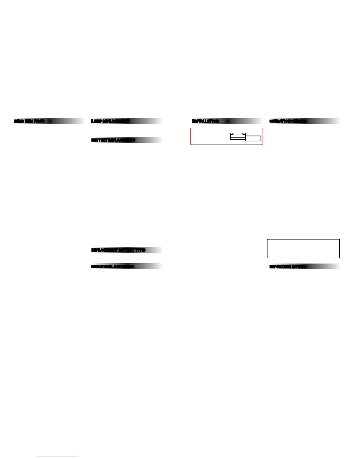
NOTE: Wires should b e
stripped 13-14.5mm
for best t with th e
push-t terminal block.
13-14 .5m m
Wire
 Loading...