

Page 1
Model:
LEDREM3 / LEDMDDEM3
LED Maintained Recessed Emergency Fittings
These instructions are provided as a guideline to assist you.
PLEASE READ THESE INSTRUCTIONS BEFORE INSTALLATION
AND RETAIN FOR FUTURE REFERENCE
Pack contents:
1 x LED tting
1 x Down legend (LED MDDEM3 only)
1 x Maintenance chec k record
INSTALLATION INSTRUCTIONS
A guide for qualied electricians
3 HOURS DURATION IN EMERGENCY MODE
REPLACEMENT BATTERY TYPE:
LEDREM3: 3.6V 1500mAh 3 x C Cells .
LEDMDDEM3: 4.8V 6 00mAh Ni-Cd batte ries.
BATTERY REPLACEMENT:
If after routi ne operation check, th e lamp does not
remain lit for the th ree hour period, a new bat tery
pack may be required.
01. Switch o the electricit y at the mains.
02. Allow batterie s to fully discharge then reconn ect
to supply and allow to ch arge for 24 hours.
03. Test again for 3 hours, if li ght does not remain lit
change the bat tery pack as follows:
04. Remove the di user.
05. Remove the two scr ews indicated on the gear tray
and open the t ting.
LEDREM3:
06. Unplug the ba ttery lead from the circ uit board.
07. Remove the two screws in the top of the g ear tray
that secure the bat tery pack in place and lif t the
battery p ack out of the tting.
08. Write current da te on the new battery pack .
09. Fit new batter y pack securing in place using th e
screws removed fr om the old pack.
10. Plug battery pa ck into circuit board.
LEDMDDEM3:
06. Disconne ct the battery from th e circuit board.
07. Cut the cable tie that secures the bat tery pack in
place and lift t he battery pack out of th e tting.
08. Write current da te on the new battery pack .
09. Fit new batter y pack securing in place using
cable tie.
10. Connect the bat tery to the circuit board.
11. Close and secure gear tray.
12. Replace diuser.
13. Restore power and allow to ch arge for 24 hours.
14. Perform full oper ation check and update test
record.
EVENTUALLY, YOU MAY WANT TO
REPLACE THIS PRODUCT:
Regulations require the recycling of Waste from
Electrical and Electronic Equipment (European “WEEE
Directive” eective August 2005—UK WEEE Regulations
eective 2nd January 2007). Environment Agency
Registered Producer: WEE/GA0248QZ.
WHEN YOUR PR ODUCT COMES TO T HE END OF ITS
LIFE OR YOU CH OOSE TO REPLACE IT, PLEA SE RECYCLE
IT WHERE FACI LITIES EXIS T DO NOT DISPOSE WI TH
HOUSEHOLD WASTE.
INDUSTRIAL BATTERIES:
Within cert ain products Eterna L ighting Ltd places lead
acid, lithium io n, nickel cadmium & nickel m etal hydride
batteries on the market. Industrial batteries are subject
to waste regulat ion under the Waste Batte ries and
Accumulators Regulations 2009 and should be disposed
of responsibl y. Purchasers may be able to disp ose of
their waste industrial batteries locally via legitimate
licensed trade waste contractors. Eterna is obliged
to take back, f ree of charge and within a rea sonable
time, waste indu strial batteries of t he same chemistry
supplied to a Purch aser, for treatment and rec ycling
and is required t o do this in any calendar year ne w
industrial ba tteries are placed on th e market. In certain
circumstances, this may include batteries not originally
supplied by Eterna. If any Purchaser requires Eterna
to take back Indus trial batteries, th ey should write to
the Operatio ns Director, Eterna Lighti ng Ltd, Huxley
Close, NN8 6AB, wh o will then advise on the n ecessary
arrangements for the receipt, proper treatment and
recycling of, the waste industrial batteries.
SPECIFICATIONS:
Volta ge: 240V
BLF / EBLF: 0.92 / 0.67
LEDREM3:
Nominal lumens: 162.3 lm
Rated wattag e: 5.20W
LEDMDDEM3:
Rated wattag e: 3.5W
Viewing dist ance: 32m
IF YOU EXPERIENCE PROBLEMS:
If you believe you r product is defec tive, please return it
to the place wher e you bought it. Our Technical Team
will gladly adv ise on any Eterna Lighting pr oduct, but
may not be able to gi ve specic instruct ions regarding
individual installations.
LEDMDDEM3
LEDREM3
Email: sales@eterna-lighting.co.uk / technical@eterna-lighting.co.uk
Visit our website: www.eterna-lighting.co.uk
Made in ChinaIssue 0418
The light source cont ained in this luminaire
shall only be rep laced by the manufacturer,
service age nt or a similar qualied pers on.
CAUTION, RISK OF ELECTRIC SHOCK.
The light source is designed to last the lifetime of the
luminaire.
Page 2
READ THIS FIRST:
Check the pack and m ake sure you have all of the
parts liste d on the front of this bookle t. If not,
contact the outlet where you bought this product.
This light ttin g must be installed by a compe tent
person in accord ance with the Building Regulat ions
making refere nce to the current edition of the I EE
Wiring Regula tions (BS7671).
As the buyer, install er and/or user of this product it
is your own responsi bility to ensure that this tt ing
is t for the purpo se for which you have intended
it. Eterna Lightin g cannot accept any liability fo r
loss, damage or premature failure resulting from
inappropriate use.
This product is designed and constructed according
to the principles o f the appropriate British Stan dard
and is intended fo r normal service. Use of this tting
in any other environm ent, for example in higher
than normal ambi ent temperatures, may result in a
foreshortened working life.
The batteri es supplied with this ttin g are
consumable par ts and therefore may be out side of
any warranty oered.
Switch o the mains be fore commencing installati on
and remove the appropriate circuit fuse.
When working at h eights, please use a suita ble
platform.
Suitable for indoor use only.
This produc t is suitable for installatio n on surfaces
with normal ammability e.g. wood, plasterboard,
masonry. It is not sui table for use on highly
ammable sur faces (e.g. polystyren e, textiles).
This produc t is suitable for mounting in pla sterboard
ceilings, suspen ded ceilings* and similar boa rd
surfaces. *C heck specication of ceili ng for
suitability.
Before makin g xing hole(s), check that there are no
obstructi ons hidden beneath the mount ing surface
such as pipes or cab les.
The chosen loc ation of your new tting shou ld allow
for the produc t to be securely mounted and s afely
connected to th e mains supply (lighting circuit).
Do not attach to su rfaces which are damp or fre shly
painted.
This produc t is designed for permanent co nnection
to xed wiring: this s hould be either a suitable
lighting circuit (p rotected with a 5 or 6 Amp MCB or
fuse) or a fused spu r (with a 3 Amp fuse) via a fused
connection u nit.
Make connecti ons to the electrical supp ly in
accordance with the f ollowing code:
Live - Brown or Red, N eutral - Blue or Black
Earth - Gree n and Yellow
When making con nections, ensure that the te rminals
are tightened se curely and that no strands of wi re
protrude. Chec k that the terminals are tightene d
onto the bared cond uctors and not onto any
insulation. Wrap lo ose terminal blocks wel l with
insulating tape.
This produc t must be connected to Ear th.
You are advised at ever y stage of your installatio n to
double-check any electrical connections you have
made. After you h ave completed your installatio n
there are elec trical tests that should b e carried out:
these tests are sp ecied in the Wiring Reg ulations
(BS7671) refer red to in the Building Regulati ons.
OPERATION CHECKS:
Periodic testin g should be carried out to ensu re
emergency lighting is operating correctly.
Interruption of t he supply, causing the tting to be
energised fro m the battery, should be car ried out by
the operation o f a local keyswitch or other iso lation
device. During th is period all ttings shou ld be
examined visu ally to ensure that they are funct ioning
correctly. At the end o f the test period the supply
shall be restore d and all indicator lamps or devi ces
checked to ensure th at the normal supply has been
restored.
DA ILY:
Visual inspec tion of the battery cha rge LED.
EACH MONTH:
Isolate the power su pply for a period sucien t to
ensure that each lamp is i lluminated. Endorse the
test record form supplied.
ONCE EACH YEAR :
Isolate the power su pply and check that the light is
still illuminate d after 3 hours. Endorse t he test record
form.
Because of the p ossibility of a failure of the n ormal
lighting supply o ccurring shortly af ter a period of
testing of the eme rgency lighting system o r during
the subsequent re charge period, all full du ration
tests shall whe rever possible be undert aken
preceding time o f low risk to allow for batter y
recharge.
NOTE: please keep th is instruction book let and
the test record in a s afe place. A re ocer or other
authorised pe rson may want to see your record of
inspection and testing.
IMPORTANT NOTES:
The ballast and control gear must be operated only within
the enclosure supplied. The gear must not be operated
outside of the enclosure.
The battery charging circuit and DC ballast are separated
from the mains by at least basic (single layer) insulation.
When energised by a constant mains supply, the battery
will be constantly charged whether or not the lamp is
illuminated. On failure of the constant mains supply,
the tting will switch automatically using transistorised
switching from battery charging to battery discharge
powering the lamp whether or not the lamp was
illuminated before the power failure. Both the mains and
battery supplies incorporate fuse protection: see tting
for location and rating.
CLEANING:
Clean this tti ng only with a soft dr y cloth.
Do not use any chemi cal or abrasive cleaner s.
INSTALLATION:
01. Undo the screws at each end of the diuser
or front plate and lift o.
02. Decide which of the cable entries you need to use
and remove one of the knock-outs if necessary.
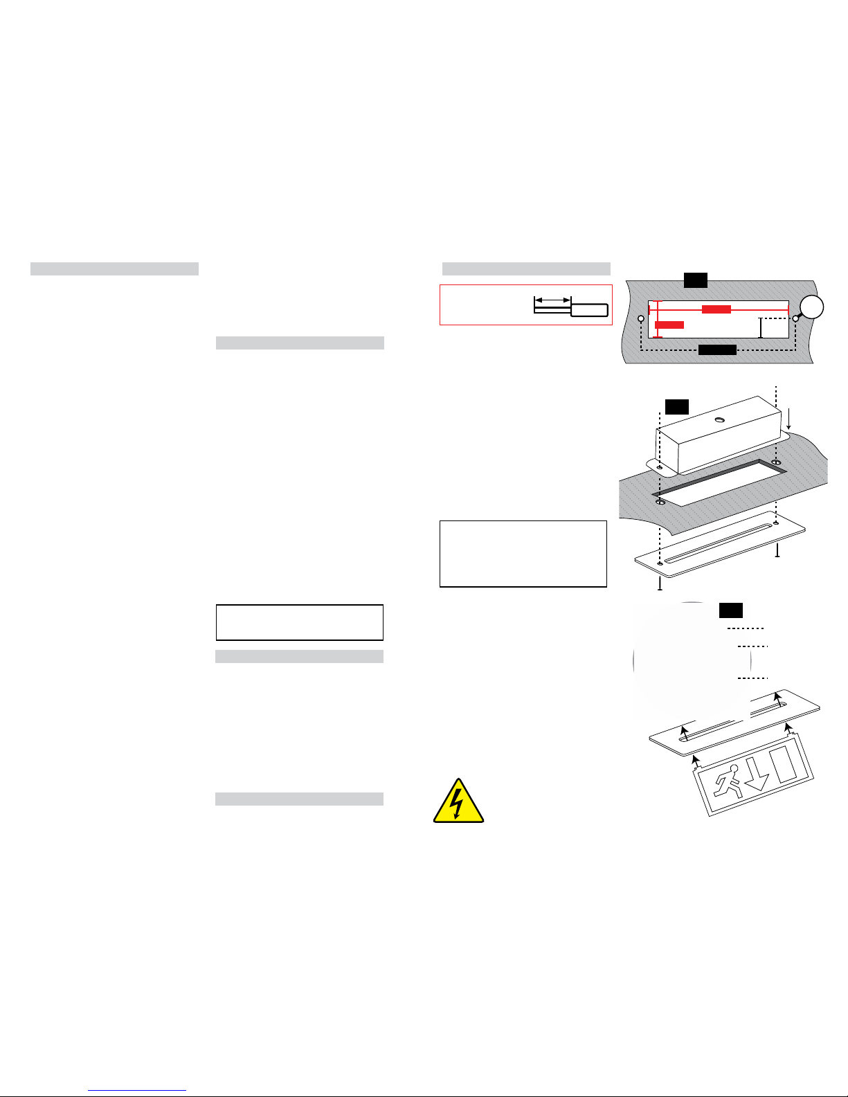
03. Cut the hole in your mounting surface using the
dimensions, see Fig 1.
04. Oer the tting up through the hole in the ceiling and
allow to rest with the two large ears on the top side of
your ceiling, see Fig 2.
05. Undo the screws at each end of the gear tray and
allow to drop open.
06. Thread the mains supply cable in through the hole in
the back of the tting.
07. Make the electrical connections according to the
colour code opposite. Take care not to leave any
strands protruding from the terminals and to tighten
all terminals securely. Ensure also that the terminals
clamp onto the bare wire and not onto the insulation.
LEDREM3 ONLY
08. To operate the tting in non-maintained mode,
remove the link from the terminals “L” & “Lsw”.
09. If the lamp is to be switched, remove the link from
between the terminals marked “L” & “Lsw” and
connect cables to and from your switch.
10. Mark the current date on the battery pack.
11. Connect the battery pack to the circuit board.
12. Close the gear tray and secure using the screws
removed earlier, see Fig 3.
13. If you have chosen one of the drop-sign models, you
need to t the sign panel into the diuser or slotted
front plate:
A) Oer the top of the sign panel into the slot in the
diuser from beneath and press down on the top of
the diuser until it rests on the shoulders at the top
of the panel.
B) Fit the small split-pins into the holes at each end
of the top edge of the sign panel and bend the ends
over to stop them from coming out again, see Fig 3.
14. Replace the diuser or front plate and tighten
securely making sure that the tting is properly
located around the hole in your ceiling.
55mm
CEILING
CEILING
115mm
320mm
375mm
ø
15mm
Screw
Legend
Folded Pin Ends
Cover
Screw
Cover
Fitting
Fig 1
Fig 2
Fig 3
NOTE: Wires should b e
stripped 13-14.5mm
for best t with th e
push-t terminal block.
13-14 .5m m
Wire
DANGER!
NOTE: this unit has a permanent live mains supply,
please ensure you isolate before removing cover.
There may also be a seperate switched supply that
controls the emergency light tting - this also needs
to be isolated.
Page 3

Month
Test
Year: Year: Year: Year: Year:
Sign Date Sign Date Sign Date Sign Date Sign Date
01 Short
02 Short
03 Short
04 Short
05 Short
06 Short
07 Short
08 Short
09 Short
10 Short
11 Short
12
3 Hour
Endurance
INSTALLATION, MAINTENANCE
AND OPERATION CHECK RECORD
Product
Code:
Product
Description:
Product
Location:
Installation
Date:
Installation
Test Duration:
Installed
By:
 Loading...