

Page 1
Model:
LEDMIRROR
LED Mirror Light With Dual Voltage Shaver Socket
These instructions are provided as a guideline to assist you.
PLEASE READ THESE INSTRUCTIONS BEFORE INSTALLATION
AND RETAIN FOR FUTURE REFERENCE
Pack contents:
1 x LED mirror light
1 x Fixing kit
INSTALLATION INSTRUCTIONS
A guide for qualied electricians
EVENTUALLY, YOU MAY WANT TO
REPLACE THIS PRODUCT:
Regulations require the recycling of Waste from
Electrical and Electronic Equipment (European
“WEEE Direc tive” eective August 20 05—UK
WEEE Regulation s eective 2nd January 20 07).
Environment Agenc y Registered Producer : WEE/
GA0248Q Z.
WHEN YOUR PR ODUCT COMES TO TH E END OF
ITS LIFE OR YO U CHOOSE TO REPLACE I T, PLEASE
RECYCLE IT W HERE FACILITIES E XIST DO NOT
DISPOSE WITH HOUSEHOLD WASTE.
CLEANING:
Clean this light t ting only with a soft dr y cloth.
Do not use any chemic al or abrasive cleaners.
IF YOU EXPERIENCE PROBLEMS:
If you believe your p roduct is defective, p lease return
it to the place where yo u bought it. Our Technical
Team will gladly advise on any Eterna Lighting
product, bu t may not be able to give specic
instructions regarding individual installations.
Email: sales@eterna-lighting.co.uk / technical@eterna-lighting.co.uk
Visit our website: www.eterna-lighting.co.uk
Made in ChinaIssue 1018
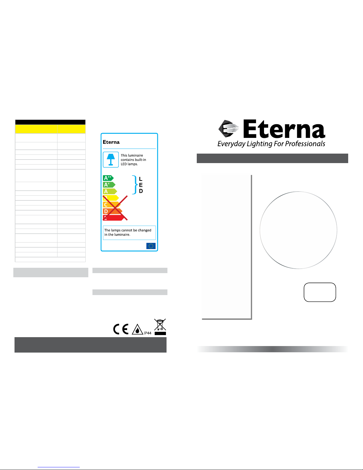
874/2012
MODELNO.
LEDMIRROR
LED LAM P SPECIFICATIO NS:
Luminaire lumens (with
diuser)
130 lm
Lumens from chip (no
diuser)
820 lm
Useful lumens
762 lm
Rated Wattage 10.3W
Rated luminous ux 762 lm
Nominal life time of the lamp 30,000 hrs
Colour temperature 3000K
Number of switching cycles
before premature lamp
failure
15,000
Warm-up time up to 60% of
the full light output
Instant full light
Dimmable No
Nominal beam angle 120°
Rated power 10.3W
Rated lamp lifetime 30,000 hrs
Lamp power factor >0.5
Lumen maintenance factor at
end of nominal life
70%
Starting time <0.5s
Colour rendering >80
Colour consistency
Within a six step
Macadam ellipse
Rated peak intensity 246cd
Rated beam angle 120°
Voltage / Frequency 240V~50Hz
Not suitable for accent lighting
Page 2
READ THIS FIRST:
Check the pack and m ake sure you have all of the
parts liste d on the front of this bookle t. If not,
contact the outlet where you bought this product.
This produc t contains glass, care must be take n when
assembling, t ting or handling to prevent per sonal
injury or damag e to the product.
This light ttin g must be installed in accorda nce
with the Building R egulations making refe rence to
the current editi on of the IEE Wiring Regulati ons
(BS7671).
Switch o the mains be fore commencing installati on
and remove the appropriate circuit fuse.
This tting cont ains an isolating transfor mer rated
at 20W maximum and is on ly intended for use with
electric sh avers. It is possible to connec t other
devices to the socke t outlet such as chargers for
electric to othbrushes provided they a re tted
with the correc t plug. Use of the socket to power
equipment requiring greater than 20W will cause
the transform er to overheat and/or stop workin g
altogether. Please re fer to the manufacturer s
instructio ns supplied with your applian ce to
determine whe ther it is suitable for use in the
location whe re you have installed your shaver light
and that the power con sumption is less than 20W.
The switch in your tting turns the light on and o.
The sockets are permanently live.
When using the shave r socket, ensure that the
correct soc ket is used according to the workin g
voltage of your ap pliance. Connecting your
appliance to the wro ng socket could cause
permanent dam age to your appliance, your ttin g
or both.
Suitable for indoor use only.
This tting is su itable for use in bathrooms in Zo ne 2
or outside of zon es. This tting must not b e installed
in zones 0, 1 see diag ram below:
This produc t is suitable for installatio n on surfaces
with normal ammability e.g. wood, plasterboard,
masonry. It is not sui table for use on highly
ammable sur faces (e.g. polystyren e, textiles).
Before makin g xing hole(s), check that there are no
obstructi ons hidden beneath the mount ing surface
such as pipes or cab les.
The chosen loc ation of your new tting shou ld allow
for the produc t to be securely mounted and s afely
connected to th e mains supply (lighting circuit).
The tting, e specially the shaver socket, s hould be
placed where it c annot be splashed.
This produc t is designed for permanent co nnection
to xed wiring: this s hould be either a suitable
lighting circuit (p rotected with a 5 or 6 Amp MCB or
fuse) or a fused spu r (with a 3 Amp fuse) via a fused
connection u nit. We recommend that the suppl y
incorporates a s witch for ease of operation .
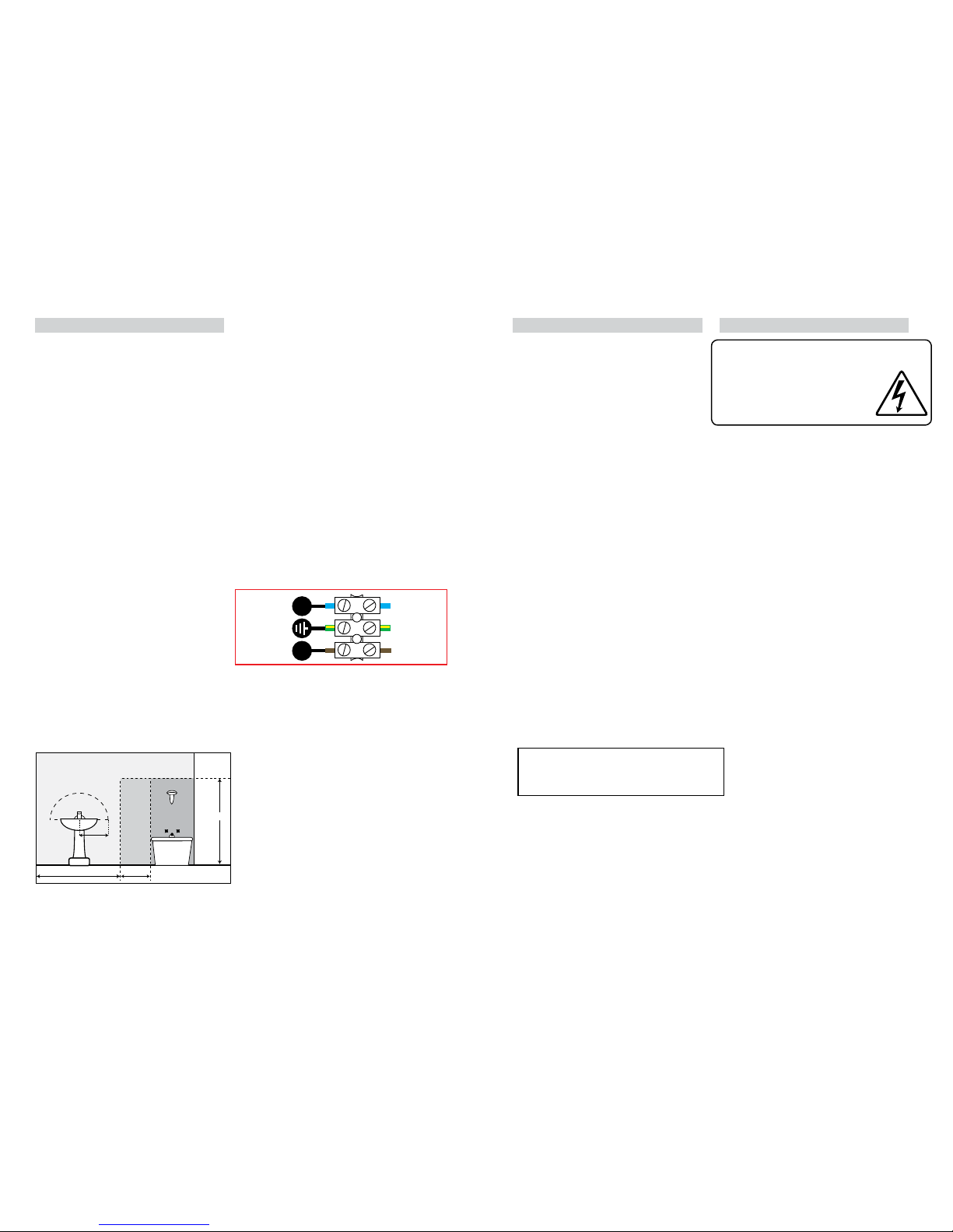
Make connecti ons to the electrical supp ly in
accordance with the f ollowing code:
Live - Brown or Red
Neutral - Blue or B lack
Earth - Gree n and Yellow
This produ ct must be connec ted to Earth.
When making con nections, ensure that the te rminals
are tightened se curely and that no strands of wi re
protrude. Chec k that the terminals are tightene d
onto the bared cond uctors and not onto any
insulation. Wrap lo ose terminal blocks wel l with
insulating tape.
Disconnect t he tting from the elec trical supply
before ash or hi gh voltage testing.
Suitable for indoor use only.
If the location o f your new tting requires th e
provision of a new el ectrical supply, the suppl y
must conform with the requirements of the Building
Regulations mak ing reference to the current e dition
of the IEE Wiring Re gulations (BS7671).
You are advised at ever y stage of your installatio n to
double-check any electrical connections you have
made. After you h ave completed your installatio n
there are elec trical tests that should b e carried out:
these tests are sp ecied in the Wiring Reg ulations
(BS7671) referred to in th e Building Regulations.
INSTALLATION:
01. Choose the loc ation for your mirror light
complying with the conditions listed opposite.
02. Lay the t ting at and remove the four scr ews
that retain the mir ror (two each side).
03. Lift the mirr or o of the tting and store sa fely.
04. Usin g the metal case as a template, mark t he
position of the xing holes. Laying a spirit l evel
across the top of the m etal case will help ensure
that your mirror is ins talled level.
05. Prepare t he xing holes as appropri ate to your
mounting surf ace.
06. Pie rce the rubber grommet in the ca ble entry
hole that you intend to u se. Do not make the
hole too large, th e rubber grommet must make a
watertight seal around the supply cable.
07. Thread the supply ca ble through the pierced
grommet.
08. Se cure the metal case to the wall us ing the
xings supplie d. If the xings supplied ar e not
appropriate to your installation, use suitable
alternatives.
09. Remove th e plastic box covering the mains
terminals.
10. Make the ele ctrical connectio ns according to the
colour code opposite.
11. Re-t the plastic cove r over the terminals.
12. Check that the so ft gasket is correctly p ositioned
around the facin g edge of the metal case.
13. Replace the mir ror and secure in position usi ng
the four screws removed previously. Press rmly
on the mirror to ensur e a tight t against the
gasket before tightening screws.
14. Restore the power and s witch on.
REPLACEMENT LAMP TYPE:
225cm
60cm240cm
60cm
radius
from tap
ZONE 1
ZONE 0
ZONE 2
ZONE 2
Bathroom Zones Diagram
The light source cont ained in this luminaire
shall only be rep laced by the manufacturer,
service age nt or a similar qualied pers on.
CAUTION, RISK OF ELECTRIC SHOCK.
The light source is designed to last the lifetime of the
luminaire.
NEUTRAL
(Power Cable)
EARTH
(Power Cable)
LIVE
(Power Cable)
N L
Yellow/Green
Blue
Brown
NOTE:
The shaver socket supplied with this unit is
designed for standard shaver plugs and may not be
suitable for other devices i.e. electric toothbrushes
 Loading...