

Page 1
These instructions are provided as a guideline to assist you.
PLEASE READ THESE INSTRUCTIONS BEFORE USING YOUR NEW FITTING
PLEASE RETAIN FOR FUTURE REFERENCE
Model:
HALFPIRBK
LED Half Lantern with 120° PIR
INSTALLATION INSTRUCTIONS
A guide for qualied electricians
Pack contents:
• Half lantern
• Mounting xtures
EVENTUALLY, YOU MAY WANT TO
REPLACE THIS PRODUCT:
Regulations require the recycling of Waste from
Electrical and Electronic Equipment (European
“WEEE Direc tive” eective August 20 05—UK
WEEE Regulation s eective 2nd January 20 07).
Environment Agenc y Registered Producer : WEE/
GA0248Q Z.
WHEN YOUR PR ODUCT COMES TO TH E END OF
ITS LIFE OR YO U CHOOSE TO REPLACE I T, PLEASE
RECYCLE IT W HERE FACILITIES E XIST DO NOT
DISPOSE WITH HOUSEHOLD WASTE.
IF YOU EXPERIENCE PROBLEMS:
If you believe your p roduct is defective, p lease return
it to the place where yo u bought it. Our Technical
Team will gladly advise on any Eterna Lighting
product, bu t may not be able to give specic
instructions regarding individual installations.
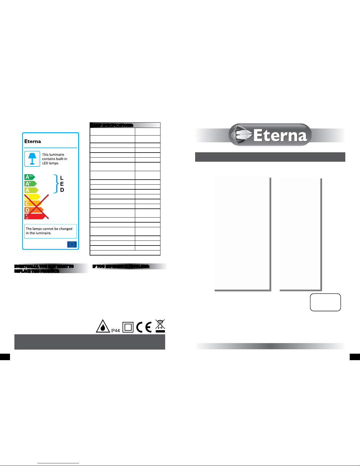
LAMP SPECIFICATIONS:
Lumens total ux
420 lm
Lumens 120° ux
380 lm
Rated Wattage 7W
Rated luminous ux 380 lm
Nominal life time of the lamp 35,000 hrs
Colour temperature 3100K
Number of switching cycles
before premature lamp failure
≥15,000
Warm-up time up to 60 % of the
full light output
Instant full light
Dimmable No
LED array dimensions (L/W) 130x35mm
Nominal beam angle 120°
Rated power 7W
Rated lamp lifetime 35,000 hrs
Lamp power factor >0.5s
Lumen maintenance factor at
end of nominal life
≥0.70
Starting time <0.1s
Colour rendering ≥80
Colour consistency
Within 6 step
Macadam ellipse
Rated peak intensity 110cd
Rated beam angle 120°
Voltage 240V
Not suitable for accent lighting
874/2012
MODELNO.
HALFPIRBK
PG 6 PG 1
Email: sales@eterna-lighting.co.uk / technical@eterna-lighting.co.uk
Visit our website: www.eterna-lighting.co.uk
Made in ChinaIssue 1216
Page 2
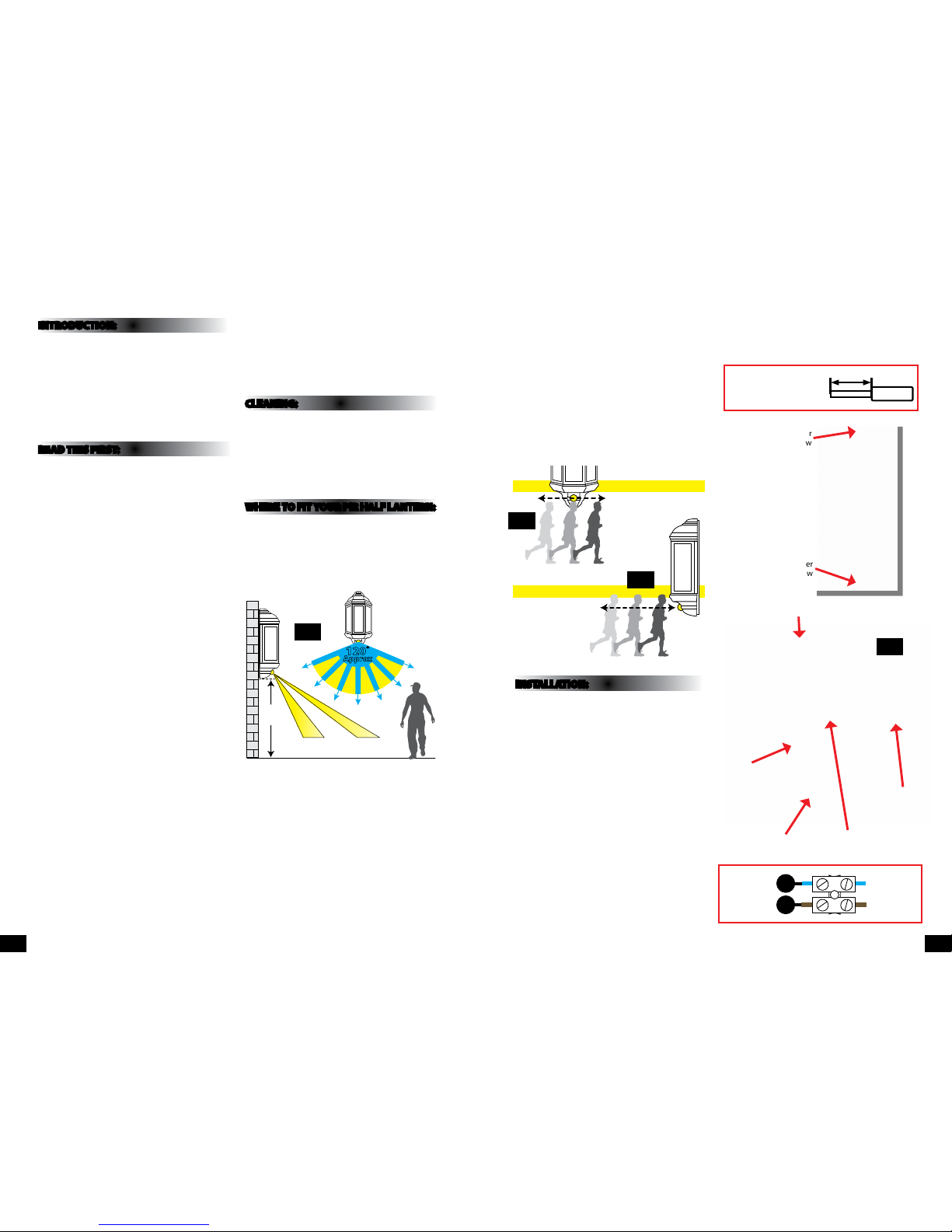
NOTE: Wires should b e
stripped 13-14.5mm
for best t with th e
push-t terminal block.
13-14 .5m m
Wire
The PIR sensor sc anning specications
(approximately 8 met res at 120°) may vary slightly
depending on the mounting height and location.
The detecti on range of the unit may also alter
with temperatu re change. Before selec ting a place
to install your PIR lant ern you should note that
movement across the s can area is more eective
than movement dire ctly towards or away from the
sensor (refer to Fig. 2 b elow).
If movement is made w alking directly towards o r
away from the senso r and not across the apparent
detection r ange will be substantially re duced (refer
to Fig. 3 below).
INSTALLATION:
01) Undo the screws at th e top and bottom of the
tting and lif t o the front.
02) Undo the s crew in the plastic cover at the bot tom
of the tting an d remove the terminal.
03) Using the b ack of the tting as a template, mar k
the location of t he xing holes.
04) Pie rce the rubber grommet in the b ack of the
tting. Make th e hole as small as possible so that
a good watert ight seal is maintained when th e
cable has been threaded through.
05) Thread the cabl e through the grommet.
06) Se cure the tting to the wall using xings
(supplied). If the x ings supplied with your t ting
are not appropriate to your installation, select
suitable alternatives.
07) Make th e connections to the termina l block
according to the colour code.
08) Re place the cover and tighten the screw.
09) Rep lace the front of the tting an d tighten the
screws.
10) Restore the power and s witch on.
INTRODUCTION:
The half lantern i ncorporates a PIR (passive Infr ared)
sensing device wh ich continuously scans a prese t
operating zon e and immediately switches th e light
on when it detec ts movement in that area.
This means that whe never movement is detecte d
within the range o f the sensor the light will switch
on automaticall y to illuminate the area you have
selected to l ight. While there is movement wi thin
range of the unit th e light will remain on.
READ THIS FIRST:
Check the pack and m ake sure you have all of the
parts liste d on the front of this bookle t. If not,
contact the outlet where you bought this product.
This produ ct must be install ed by a competent
person in accordance with the current building
and IEE wiring regulations.
As the buyer, install er and/or user of this product it
is your own responsi bility to ensure that this tt ing
is t for the purpo se for which you have intended
it. Eterna lightin g cannot accept any liability fo r
loss, damage or premature failure resulting from
inappropriate use.
This product is designed and constructed according
to the principles o f the appropriate British Stan dard
and is intended fo r normal domestic ser vice. Using
this tting in any oth er environments may result in a
shortened working life.
Switch o the mains be fore commencing installati on
and remove the appro priate circuit fuse or lock o
MCB.
This unit is suitab le for outdoor use.
This produc t is designed for permanent co nnection
to xed wiring: this m ust be a suitable circuit
(protected w ith the appropriate MCB or fuse).
Before makin g xing hole(s), check that there are no
obstructi ons hidden beneath the mount ing surface
such as pipes or cab les.
Make sure that the xi ngs are strong enough to
support the co nsiderable weight of the t ting and
hold it rigidly.
When making con nections ensure that the ter minals
are tightened se curely and that no strands of wi re
protrude. Chec k that the terminals are tightene d
onto the bared cond uctors and not onto any
insulation.
This produc t is not intended to be used by childr en
and persons wi th sensory, physical and/or ment al
impairments th at would prevent them from using i t
saf ely.
You are advised at ever y stage of your installatio n to
double-check any electrical connections you have
made. After you h ave completed your installatio n
there are elec trical tests that should b e carried out,
these tests are sp ecied in the current IEE wir ing and
building regulations.
This product is double insulated. DO NOT CONNEC T
ANY PART TO EA RTH.
CLEANING:
To avoid dust build-up an d ensure proper
functionin g of the half lantern light, pleas e wipe the
sensor lens light ly with a damp cloth every 3 month s.
Disconnect t he power and clean the exte rior only of
this tting wit h a moist (not wet) cloth.
Do not use any chemic al or abrasive cleaners.
WHERE TO F IT YOUR PIR HALF LANTERN:
To achieve best results we su ggest you take the
following points into consideration:
Do not mount on a sur face that has vibration.
Ideally the PIR hal f lantern should be mounted 1.8
to 2.5 metres (6 to 8f t) above the area to be scanne d
(refer to Fig. 1 below).
To avoid damage to the unit do not ai m sensor
towards the sun.
Avoid positioning th e sensor unit adjacent to a
bright light source w hich may prevent the unit from
operating whe n the lux control is set to operate i n
dark conditions.
Avoid nuisance false t riggering by directing s ensor
away from:
Trees and shrubs
Reective su rfaces such as smooth white w alls
Swimming pools
Heat sources such as b oiler ues
1.8-
2.5M
4M 8M
120˚
Approx
Fig 1
EFFECTIVE:
Movement across
scan area
LESS EFFECTIVE:
Movement
directly in front
of scan area
Fig 2
Fig 3
Fig 4
Unscrew cover to get
access to terminal bl ock
PIR
Cover
screw
Cover
screw
Cover
screw
Push type
terminal block
Rubber
grommet
LN
Blue
(Power Cable)
Brown
(Power Cable)
Blue
(Power Cable)
Brown
(Power Cable)
PG 2 PG 3
Page 3

TROUBLESHOOTING AND USER HINTS:
Note: all passive infra re d detectors are more se nsitive in cold and dry weather th an warm and wet weather.
SPECIFICATIONS:
• Det ection range: Approx. 120° (hor izontal), Max. 8 metres.
• Duration time: f rom 5 sec - 5 mins. (adjustable).
• Facto ry preset PIR - no override fa cility.
• LUX - adjustable.
LAMP REPLACEMENT:
PROBLEM POSSIBLE CAUSE SUGGESTED REMEDY
Light does not switch on
when there is movement
in the detection area.
1. No mains voltage Check all connections, and MCB Fuses / switches
2. Nearby lighting is too bright Relocate the unit
3. Wired incorrectly
Check wiring and conrm its wired as per the
wiring diagram
Light switches on for no
apparent reason (false
trigger)
1. Heat sources such as air-con, vents, heaters, ues,
other outside lighting, moving cars trees or shrubs
are activating sensor
Relocate tting
2. Animals / birds activating sensor Relocate tting
3. I nterference from on/o switching of electric fans
or lights on the same circuit as your tting.
(This problem does not always occur but a faulty
switch may cause the tting to switch on)
Should the false triggering become, troublesome,
consider:
(a) Replacing a faulty switch
(b) Connecting the tting to a separate circuit (in
most cases where one or more of the above
suggestions have been carried out, false
triggering has been reduced)
4. Reec tion from swimming pool, or reective
surface such as smooth white walls
Relocate tting
Light remains on Continuously false triggered Relocate tting
Light remains on at
nighttime
Possible heat source in detection zone
Cover PIR sensor lens with a thick cloth, if the
light turns o check detection area for heat or
reective source, reposition head
When setting the lux
controls in daylight
the detection distance
becomes shorter
Interference by sunlight Re-test at night
UNDERSTANDING THE CONTROLS:
Please refer to Fig. 5 b elow.
ADJUSTING THE DURATION TIME:
The length of tim e that the light remains switche d on after activation ca n be adjusted from 5 seconds to 5
minutes. Rotatin g the TIME screw (+) to (-) will reduce the time duration.
Note: once the light has be en triggered by the PIR sensor a ny subsequent detection w ill start the timed per iod
again from the beginning.
ADJUSTING THE LUX CONTROL LEVEL:
The lux control mo dule has a built-in sensing devi ce (photocell) that detect s daylight and darkness. Th e (R)
position denotes that the b ulkhead light can work at day and n ight, and the () position will onl y work at night.
You can set to operate the li ght at the desired level by adjusti ng the LUX screw.
SETTING THE CONTROLS:
Turn the LUX control knob t o light (R) position, at this stage ensure tha t the time control screw is set at
minimum duration t ime (-) position. The bulkhea d light will now switch on and remain o n for about 5 seconds.
Direct the se nsor toward the desired area to be s canned.
Adjust time control to required setting.
To set the LUX level at which th e lamp will automatically switc h “on” at night, turn the LUX control screw from
daylight to night (). If the la mp is required to switch on earlie r, e. g. dusk, wait for the desired envi ronment
light level, then sl owly turn the LUX control screw towards t he daylight (R) while someone walk s across the
centre of the area to be d etected. When the lamp s witches on, stop adjusting.
Fig 5
PG 4 PG 5
The light source cont ained in this luminaire
shall only be rep laced by the manufacturer,
service age nt or a similar qualied pers on.
CAUTION, RISK OF ELECTRIC SHOCK.
The light source is designed to last the lifetime of the
luminaire.
 Loading...