

Page 1
Issue 2013
Model:
FL124BPIR
23W Low Energy Floodlight With 180° PIR
These instructions are provided as a guideline to assist you.
PLEASE READ THESE INSTRUCTIONS BEFORE INSTALLATION
AND RETAIN FOR FUTURE REFERENCE
Pack contents:
1 x Fitting
1 x 23W ES CFL lamp
FOR PRODUCT ADVICE:
• T: 01933 673 144
• F: 01933 678 083
• E: sales@eterna-lighting.co.uk
Visit our website:
www.eterna-lighting.co.uk
INSTALLATION INSTRUCTIONS
A guide for qualied electricians
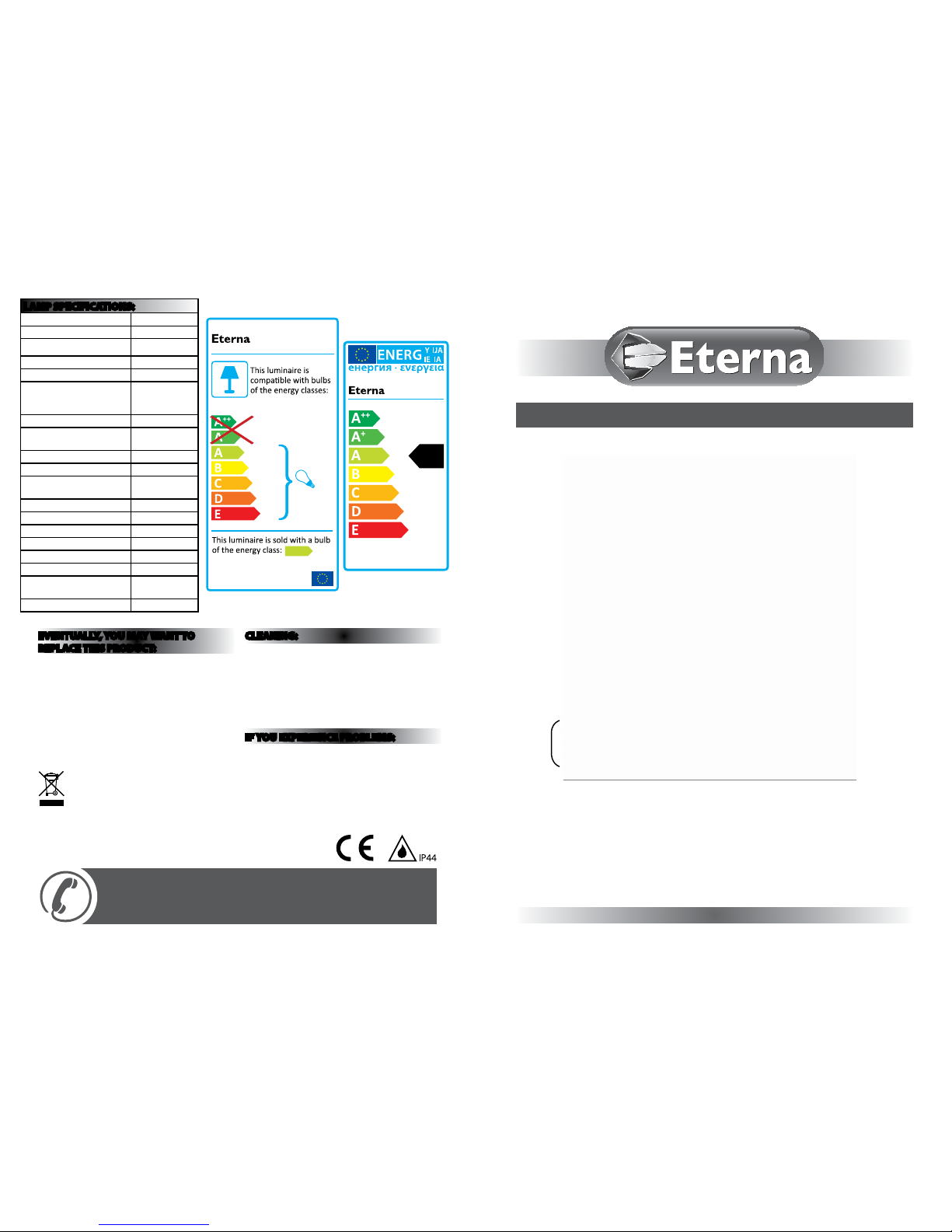
874/2012
A
MODELNO.
FL124BPIR
MODELNO.
A
++
XXX kWh/1000h
22.50
CFL23W
A
EVENTUALLY, YOU MAY WANT TO
REPLACE THIS PRODUCT:
Regulations require the recycling of Waste from
Electrical and Electronic Equipment (European
“WEEE Direc tive” eective August 20 05—UK
WEEE Regulation s eective 2nd January 20 07).
Environment Agenc y Registered Producer : WEE/
GA0248Q Z.
WHEN YOUR PR ODUCT COMES TO TH E END OF
ITS LIFE OR YO U CHOOSE TO REPLACE I T, PLEASE
RECYCLE IT W HERE FACILITIES E XIST DO NOT
DISPOSE WITH HOUSEHOLD WASTE.
CLEANING:
To avoid dust build-up an d ensure proper
functionin g of the oodlight, please w ipe the sensor
lens lightly with a da mp cloth every 3 months.
Disconnect t he power and clean the exte rior only of
this tting wit h a moist (not wet) cloth.
Do not use any chemic al or abrasive cleaners.
IF YOU EXPERIENCE PROBLEMS:
If you believe your p roduct is defective, p lease return
it to the place where yo u bought it. Our Technical
Team will gladly advise on any Eterna Lighting
product, bu t may not be able to give specic
instructions regarding individual installations.
For breakage inf ormation visit:
www.eterna-lighting.co.uk
LAMP SPECIFICATIONS:
Voltage 220-240V
Frequency 50Hz
Nominal lumens
1371 lm
Wattage 23W
Nominal life time of the lamp 10,000 hrs
Number of switching cycles
before premature lamp
failure
30,000
Colour temperature 6400K
Warm-up time up to 60 % of
the full light output
40s
Dimmable No
Lamp dimensions (mm) 140 x 59
Lamp mercury content to an
accuracy of 0.1mg
2.5
Cap type ES (E27)
Rated Wattage 22.5W
Rated luminous ux 1371 lm
Rated lamp lifetime 10,000
Colour rendering index Ra 80%
Lamp power factor 0.55
Lumen maintenance factor at
end of nominal life
50%
Starting time 0.9s
Page 2
READ THIS FIRST:
Check the pack and m ake sure you have all of the
parts liste d on the front of this bookle t. If not,
contact the outlet where you bought this product.
This produc t contains glass, care must be take n when
assembling, t ting or handling to prevent per sonal
injury or damag e to the product.
This light ttin g must be installed by a compe tent
person in accord ance with the Building Regulat ions
making refere nce to the current edition of the
IEE Wiring Regu lations (BS7671). The Building
Regulations may b e obtained from HMSO or view ed
and downloaded from www.communities.gov.uk
following the lin k for Building Regulations .
As the buyer, install er and/or user of this product it
is your own responsi bility to ensure that this tt ing
is t for the purpo se for which you have intended
it. Eterna Lightin g cannot accept any liability fo r
loss, damage or premature failure resulting from
inappropriate use.
The lamps (bulbs/tubes) supplied with this tting are
consumable par ts and therefore may be out side of
any warranty oered.
Switch o the mains be fore commencing installati on
and remove the appropriate circuit fuse.
When working at h eights, please use a suita ble
platform.
Disconnect t he tting from the elec trical supply
before ash or hi gh voltage testing.
Suitable for indoor and outdoor use.
This produc t is suitable for installatio n on surfaces
with normal ammability e.g. wood, plasterboard,
and masonry. It is not s uitable for use on highly
ammable sur faces (e.g. polystyren e, textiles).
Before makin g xing hole(s), check that there are no
obstructi ons hidden beneath the mount ing surface
such as pipes or cab les.
The chosen loc ation of your new tting shou ld allow
for the produc t to be securely mounted and s afely
connected to th e mains supply (lighting circuit).
When choosing th e location for your new tt ing,
ensure that the xin gs will be anchored in a solid
surface e.g. con crete, brick or a joist—do not x
directly onto panelling, cladding, plasterboard etc.
If the location o f your new tting requires th e
provision of a new el ectrical supply, the suppl y
must conform with the requirements of the Building
Regulations mak ing reference to the current e dition
of the IEE Wiring Re gulations (BS7671).
This produc t is designed for permanent co nnection
to xed wiring: this s hould be either a suitable
lighting circuit (p rotected with a 5 or 6 Amp MCB or
fuse) or a fused spu r (with a 3 Amp fuse) via a fused
connection unit.
We recommend that the s upply incorporates a
switch for ease of o peration.
Make connecti ons to the electrical supp ly in
accordance with the f ollowing code:
Live - Brown or Red
Neutral - Blue or B lack
Earth - Gree n and Yellow
When making con nections, ensure that the te rminals
are tightened se curely and that no strands of wi re
protrude. Chec k that the terminals are tightene d
onto the bared cond uctors and not onto any
insulation.
This produc t must be connected to Ear th.
IMPORTANT: Always switch o at the mai ns before
changing the lamp.
You are advised at ever y stage of your installatio n to
double-check any electrical connections you have
made. After you h ave completed your installatio n
there are elec trical tests that should b e carried out:
these tests are sp ecied in the Wiring Reg ulations
(BS7671) referred to i n the Building Regulations
LAMP REPLACEMENT:
01. Switch o the electricit y at the mains.
02. Using a cross-headed scr ewdriver, undo the
screws that secur e the diuser and allow to hang
down.
03. Remove the lamp.
04. Insert new lamp.
05. Replace the diuser and s ecure in position
making sure that th e gasket is correctly
positioned and compressed.
06. Restore th e power and switch on.
REPLACEMENT LAMP TYPE:
Fitting requi res 1 x 23W ES helical CFLi 6400K
(included) or energy saving alternative.
Fitting is rated a t 23W max.
SPECIFICATION:
Detection r ange: max. 12 metres at approx. 180° scan
Duration time ad justable: (2±0.5) minutes to (6±1)
minutes
Detection c ircuitry: Passive Infra -Red (PIR)
Power required: 220 -230V ~ 50Hz
Maximum load: 2 3W E27 CFLi lamp
Recommende d power supply cable: H05RN -F 3G
1.0m m
2
Protection: class I
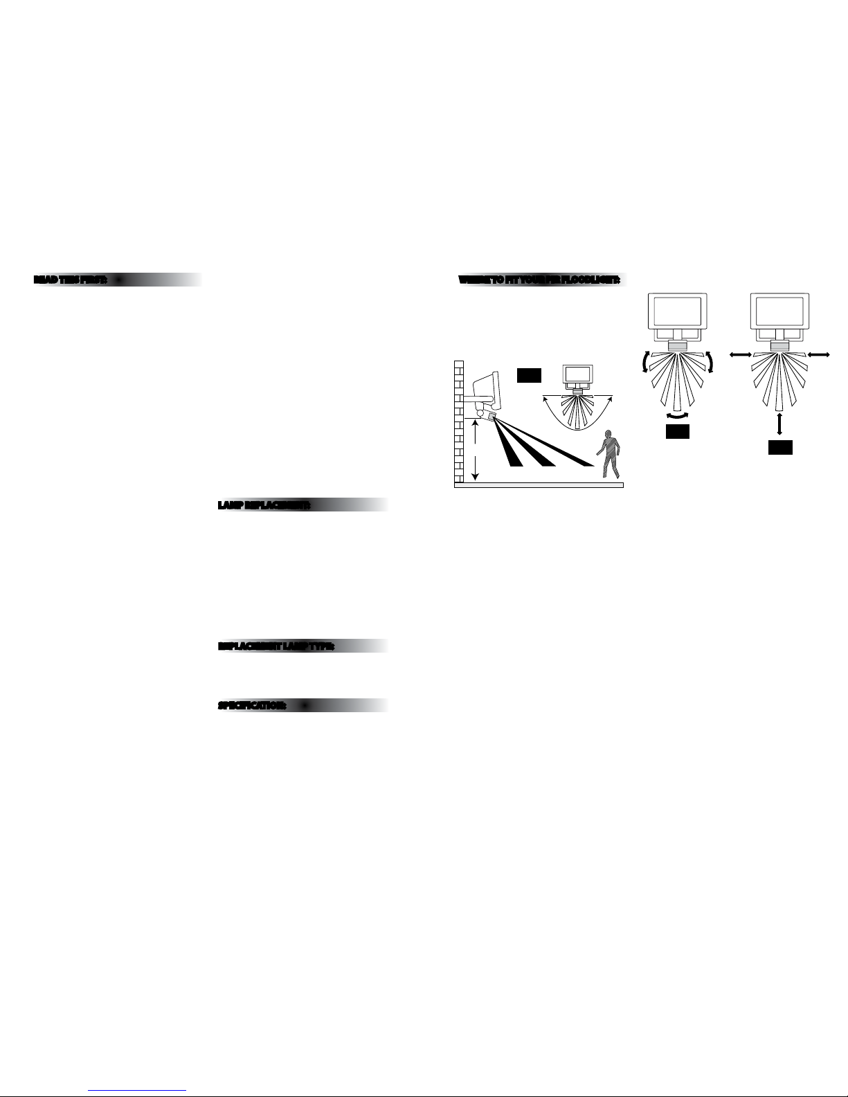
WHERE TO F IT YOUR PIR FLOODLIG HT:
To achieve best results we su ggest you take the
following points into consideration:
Do not mount on a sur face that has vibration.
Ideally the PIR o od light should be mounted 1.8 to
2.5 metres (6 to 8f t) above the area to be scanned
(refer to Fig.1 below).
To avoid damage to the unit do not ai m sensor
towards sun.
Avoid positioning th e sensor unit adjacent to a
bright light source w hich may prevent the unit from
operating whe n the lux control is set to operate i n
dark conditions.
Avoid nuisance/ fals e triggering by directin g sensor
away from:
• Trees and shrubs
• Reective su rfaces such as smooth white w alls
• Swimming pools
• Heat sources such as b oiler ues
The PIR sensor sc anning specications
(approximately 12 metres at 180°) may v ary slightly
depending on the mounting height and location.
The detecti on range of the unit may also alter w ith
temperature cha nge. Before selectin g a place to
install your PIR o odlight you should note that
movement across the s can area is more eective
than movement dire ctly towards or away from the
sensor. (Refer to Fig. 2 opposite).
If movement is made w alking directly towards o r
away from the senso r and not across the sensor
the apparent dete ction range will be subs tantially
reduced (refer to Fig . 3 opposite).
Fig 1
TIME SENS LUX
2.5M
4M 8M 12M
180˚
Appr.
L N
Yellow/Green
(Power Cable)
Blue
(Power Cable)
Brown
(Power Cable)
Black (PIR Wire)
Yellow/Green
(Lamp Wire)
Blue (Lamp Wire)
Blue (PIR Wire)
Brown (PIR Wire)
Brown
(Lamp Wire)
Terminal Block
Power
Cable
L N
Brown (power cable)
Blue
(power
cable)
Yellow / Green
(power cable)
Screw
Cable Gland
Junction Box
Locking Nut
Fig 3
Eective
Less
Eective
Fig 2
L N
Black (PIR Wire)
Yellow/Green
(Lamp Wire)
Blue (Lamp Wire)
Blue (PIR Wire)
Brown (PIR Wire)
Brown
Terminal Block
L N
Blue
(power
cable)
Yellow / Green
(power cable)
Page 3

INSTALLATION:
TIME SENS LUX
2.5M
4M 8M 12M
180˚
Appr.
L N
Yellow/Green
(Power Cable)
Blue
(Power Cable)
Brown
(Power Cable)
Black (PIR Wire)
Yellow/Green
(Lamp Wire)
Blue (Lamp Wire)
Blue (PIR Wire)
Brown (PIR Wire)
Brown
(Lamp Wire)
Terminal Block
Power
Cable
L N
Brown (power cable)
Blue
(power
cable)
Yellow / Green
(power cable)
Lamp Cover
Screw
Cable Gland
Wall
Mounting
Support
Screws
X 2
Wall Mounting
Support Bracket
Junction Box
Locking Nut
Fig 4
INSTALLATION:
When installin g the PIR ood light refer to Fig.4
opposite.
01) Switch o the mains be fore commencing
installation.
02) Remove th e wall bracket from the ttin g by
removing the scr ews and nuts from each side.
Take care not to lose any of these p arts as the
nuts are not capti ve within the tting - see Fig. 4.
03) Using the b racket as a template mark and then
drill the appropriate xing holes.
04) Se cure the bracket with suitab le xings (not
supplie d).
05) Unscr ew the junction box cover screws a nd
remove cover, unscrew the glan d nut and loosen
the cable restr aint clamp. Connect the power
cable (not include d) to the terminal block, s ee
Fig. 4. Ensure the cab le passes through the cable
gland and gasket.
06) Re -t the terminal block , tighten the cable
restraint clamp, tighten the gland nut and re-t
the c over.
07) Fix ho using back into wall mounting bra cket and
secure with screws, washers and nuts previously
removed.
08) Uns crew the lamp cover screws and t the
lamp making sure it i s fully screwed into the
lampholder.
09) Adjus t the direction of the oo dlight and tighten
the head xings e nsuring that you have used the
lock washers.
10) Restore mains power.
11) Adju st the PIR sensor oodlight to th e desired
settings.
IMPORTANT
Loosen the lock n uts and screws on sensor and
oodlight before making any adjustments.
UNDERSTANDING THE CONTROLS:
(Referring to Fig.5 opposite)
ADJUSTING TH E DURATION TIME:
The length of tim e that remains switched on af ter
activation c an be adjusted from (2±0.5) mi nutes to
(6±1) minutes. Rotating the TIME kno b anticlockwise
from (+) to (-) will reduce the duration t ime.
Note: Once the li ght has been triggered by the PI R
sensor any subseq uent detection will sta rt the timed
period again from the beginning.
ADJUSTING TH E LUX CONTROL LEVEL:
The lux control mo dule has a built-in sensing devi ce
(photocell) that d etects daylight and dark ness. The
(R) position denotes that th e oodlights can work at
day and night, and the (
) position will on ly work at
night. You can set to oper ate the unit at the desired
level by adjusting t he LUX knob.
ADJUSTING TH E SENSITIVITY:
The SENS knob cont rols the distance from which th e
PIR sensor can be tr iggered. Turning the SENS knob
from (+) to (-) will decrease the sensi tivity.
SETTING THE CONTROLS:
Turn the LUX control knob t o light (R) position, turn
the wall switch on an d wait half a minute for the
control circuit to st abilize. At this stage ensure that
the TIME control k nob is set at minimum duration
time (-) position (rotatin g the TIME knob anticlockwise to s top-position). The oo dlight will now
switch on and remai n on for about 2 minuites afte r
each detection.
1) Direct th e sensor toward the desired are a to be
scanned by adjus ting the swivel joint on the
sensor arm.
IMPORTANT
Loosen the lock n uts and screws on sensor and
oodlight before making any adjustments.
2) Have anot her person move across the cente r of the
area to be scanne d and slowly adjust the angle of
the sensor arm unt il the unit senses the presence
of the moving per son, causing the oodligh t to
switch on (refer to Fig. 2).
3) Adjust time control to required setting.
4) To set the light le vel at which the oodlight will
automatically s witch “on” at night, turn the LUX
control knob fr om daylight (R) to night (
). If the
oodlight is req uired to switch on earlier, e.g.
dusk, wait for th e desired light level, then slow ly
turn the LUX contro l knob towards daylight while
someone walk s across the center of the area to be
detected. W hen the oodlight switche s on, release
the LUX control kn ob. You may need to make
further adj ustments to achieve your ideal li ght
level setting.
Fig 5
TIME SENS LUX
L N
Yellow/Green
(Power Cable)
Blue
(Power Cable)
Brown
(Power Cable)
Black (PIR Wire)
Yellow/Green
(Lamp Wire)
Blue (Lamp Wire)
Blue (PIR Wire)
Brown (PIR Wire)
Brown
(Lamp Wire)
Terminal Block
Power
Cable
L N
Brown (power cable)
Blue
(power
cable)
Yellow / Green
(power cable)
Junction Box
Locking Nut
Page 4

TROUBLESHOOTING AND USER HINTS:
NOTE: all passive infr a red detectors are more s ensitive in cold and dry weathe r than warm and wet weather.
PROBLEM POSSIBLE CAUSE SUGGESTED REMEDY
Light does not switch on
when there is movement
in the detection area.
1. No mains voltage Check all connections, and MCB fuses / switches
2. Nearby lighting is too bright Redirect sensor or relocate the unit
3. Controls set incorrectly Readjust sensor angle or control knob
4. Lamp blown Check lamp functions and replace if necessary
5. Lamp not tted correctly
Make sure the lamp is correctly seated in the
lampholder
6. Wired incorrectly
Check wiring and conrm its wired as per the
wiring diagram
7. Sensor positioned in wrong direction
Adjust angle and direction of PIR for best results
walk across beam
Light switches on for no
apparent reason (false
trigger)
1. Heat from lamp body activating sensor
Adjust PIR sensor or oodlight to allow a
minimum gap of 40mm between oodlight body
and sensor head
2. Heat sources such as air-con, vents, heaters, ues,
other outside lighting, moving cars trees or shrubs
are activating sensor
Adjust direction of sensor head away from these
sources
Reduce sensitivity
3. Animals / birds activating sensor Redirecting sensor head may help
4. I nterference from on/o switching of electric
fans or lights on the same circuit as your security
oodlight.
(This problem does not always occur but a faulty
switch or noisy uorescent light may cause the
security oodlight to switch on)
Should the false triggering become, troublesome,
consider:
(a) Replacing a faulty switch
(b) Replacing noisy uorescent tubes and/or
starters
(c) Connecting the oodlight to a separate
circuit (in most cases where one or more of
the above suggestions have been carried out,
false triggering has been reduced)
5. Reec tion from swimming pool, or reective
surface such as smooth white walls
Redirect sensor
Light remains on
1. Continuously false triggered Redirecting sensor head may help
2. Time is set to long Reduce time
Light remains on at
nighttime
Possible heat source in detection zone
Cover PIR sensor lens with a thick cloth, if the
light turns o check detection area for heat or
reective source, reposition head
Light switches on during
daylight hours
LUX control knob is set to daylight position
Turn the LUX control knob to desired light level
setting
When setting the lux
controls in daylight
the detection distance
becomes shorter
Interference by sunlight Re-test at night
 Loading...