

Eterna EX360PIRWH Installation Instructions Manual
INSTALLATION INSTRUCTIONS
Pack contents:
1 x Stand-alone PIR sensor
1 x Corner mounting bracket
1 x Fixing pack
A guide for qualied electricians
Model:
EX360PIRWH
360° PIR Movement Detector
These instructions are provided as a guideline to assist you.
PLEASE READ THESE INSTRUCTIONS BEFORE INSTALLATION
AND RETAIN FOR FUTURE REFERENCE
Email: sales@eterna-lighting.co.uk / technical@eterna-lighting.co.uk
Visit our website: www.eterna-lighting.co.uk
Made in ChinaIssue 1016
EVENTUALLY, YOU MAY WANT TO
REPLACE THIS PRODUCT:
Regulations require the recycling of Waste from
Electrical and Electronic Equipment (European
“WEEE Direc tive” eective August 20 05—UK
WEEE Regulation s eective 2nd January 20 07).
Environment Agenc y Registered Producer : WEE/
GA0248Q Z.
WHEN YOUR PR ODUCT COMES TO TH E END OF
ITS LIFE OR YO U CHOOSE TO REPLACE I T, PLEASE
RECYCLE IT W HERE FACILITIES E XIST DO NOT
DISPOSE WITH HOUSEHOLD WASTE.
CLEANING:
To avoid dust build-up an d ensure proper
functionin g of the PIR sensor, please wipe the se nsor
lens lightly with a dr y cloth every 3 months.
Do not use any chemic al or abrasive cleaners.
IF YOU EXPERIENCE PROBLEMS:
If you believe your p roduct is defective, p lease return
it to the place where yo u bought it. Our Technical
Team will gladly advise on any Eterna Lighting
product, bu t may not be able to give specic
instructions regarding individual installations.
EFFECTIVE:
Movement across
scan area
LESS EFFECTIVE:
Movement
directly in front
of scan area
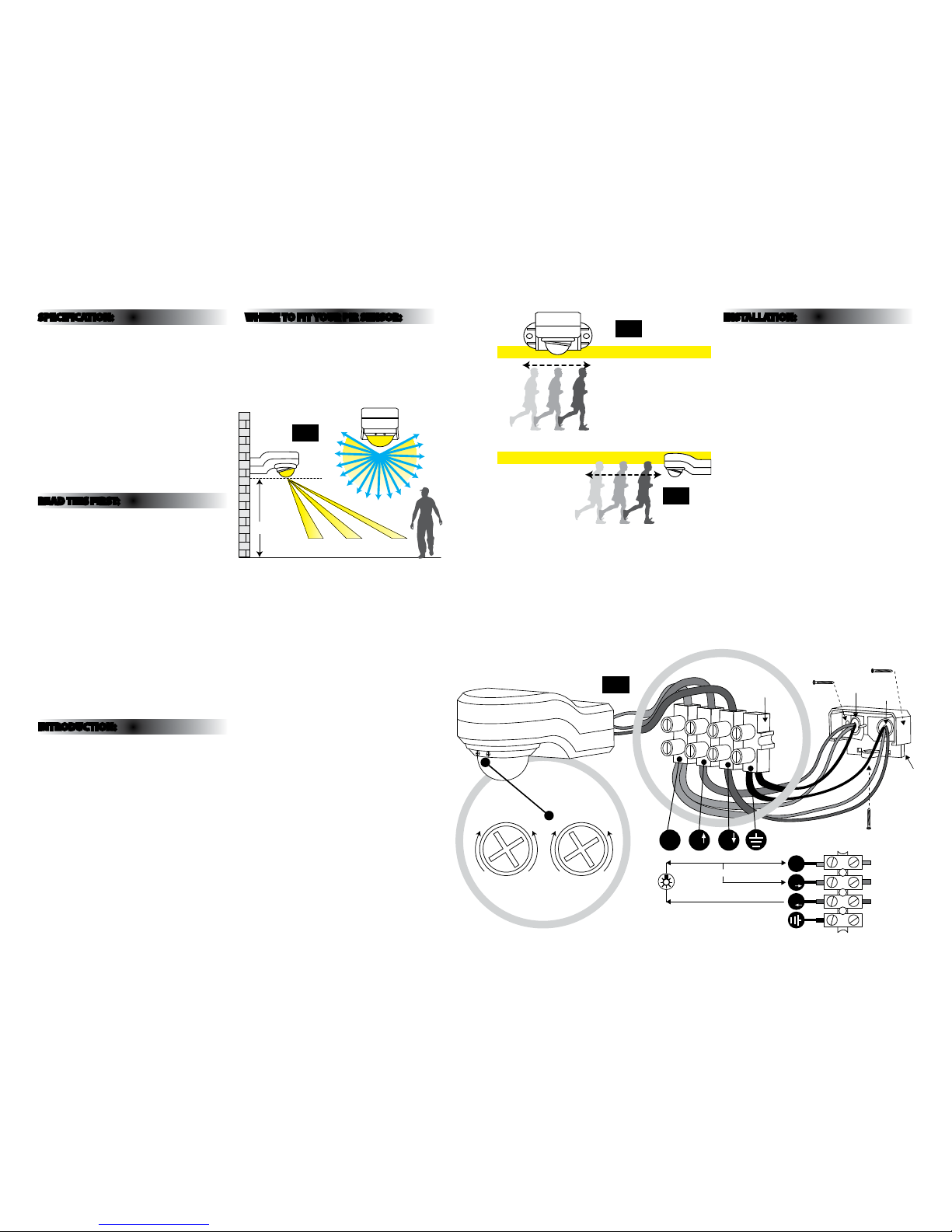
INSTALLATION:
When installin g the PIR sensor please refer to Fi g. 4
belo w.
01) Switch o the mains be fore commencing
installation.
02) Unscrew th e bottom screw and remove bac k
plate.
03) Using bac k plate as a template to mark the
mounting surf ace.
04) Dr ill and plug the xing holes .
05) Pass bo th the feed and load cables t hrough the
rubber gromme t in the back plate.
06) Fix th e back plate to the mounting sur face
with the screws sup plied, noting the mounting
direction (in dicator on plastic back plate)
.
07) Conne ct the main cable and load c able to the
terminal block (s ee Fig. 4 below)
(Cable for 6A/23 0VAC: 3 cores not less th an
1.5m m
2
conducting cross-sectional area, not
included).
08) Re t the terminal block.
09) Fit th e body to the back cover and secure u sing
screw.
10) Restore mains power.
11) Adjus t the PIR sensor to desired work ing
requirements.
SPECIFICATION:
• Det ection range: Approx. 12 metres at 240 °
(horizontal) and 130° (vertical)
• Dur ation time: from 10(±5) seconds up to 4(±1)
minutes adjustable
• Weatherproof : IP44
• Voltage: 230-240VAC~50Hz
• Fuse Rating: 6.3A /250VAC • 5x20mm
• Watta ge:
Max. 1000W inca ndescent lamp (resistive load)
Max. 300W uorescent lamp (inductive load)
Max. 150W LED (no more than 8 light s)
• Lux Con trol Level: from daylight to night adj ustable
READ THIS FIRST:
Check the pack and m ake sure you have all of the
parts liste d on the front of this bookle t. If not,
contact the outlet where you bought this product.
This produ ct must be install ed by a qualied
electrician in accordance with the current
building and IEE wiring regulations.
The installer m ust ensure that this tting is sui table
for the purpos e intended. Eterna Lighting Ltd ca nnot
accept any liabilit y for loss, damage or prematur e
failure resulting from inappropriate use.
This unit is suitab le for outdoor use.
This produc t is designed for permanent co nnection
to xed wiring: this m ust be a suitable circuit
protected wi th the appropriate MCB or fuse.
This tting is d ouble insulated and does not re quire
an earth (however t here is an earth post for ear th
continuity).
INTRODUCTION:
The PIR (passive Inf rared) sensing device
continuously scans a preset operating zone and
immediately sw itches the load-light on w hen it
detects move ment in that area. While there is
movement within ra nge of the unit the load light wil l
remain on.
WHERE TO F IT YOUR PIR SENSOR:
To achieve best results we su ggest you take the
following points into consideration:
Do not mount on a sur face that suers vibratio n.
The PIR sensor sho uld be mounted 2.5 to 3 metre s
above the area to be sc anned (refer to Fig. 1 below).
To avoid damage to the unit do not ai m the sensor
eyeball towards the sun.
Avoid positioning th e sensor unit adjacent to a
bright light source w hich may prevent the unit from
operating whe n the lux control is set to operate i n
dark conditions.
Avoid nuisance false t riggering by directing s ensor
away from:
• Trees and shrubs
• Reective su rfaces such as smooth white w alls
• Swimming pools an d ponds
• Heat sources such as b oiler ues
The PIR sensor de tection range may vary s lightly
depending on the mounting height, location and
temperature changes.
For optimal per formance ensure your senso r is
installed wh ere pedestrian trac cros ses the
detection z one (refer to Fig. 2 opposite). Note that
movement direc tly towards or away from the senso r
is less eecti ve in triggering the sensor. (refer to Fi g.
3 opposite).
N
Power
Cable
Mounting
Screws x 2
Load
Cable
N L L
Terminal Block
LL
Earth
Blue (PIR)
Brown (PIR)
Black (PIR)
230VAC 50Hz
Main Power
Back
Plate
+
_
TIME
✺
‡
LUX
Fig 2
Fig 3
Fig 4
2.5-3m
4M 8M 12M
Fig 1
 Loading...