

Eterna ELEGAN5EM3 Installation Instructions Manual
Model:
ELEGAN5EM3
5ft LED Twin Slimline Ceiling Fitting With Emergency
These instructions are provided as a guideline to assist you.
PLEASE READ THESE INSTRUCTIONS BEFORE INSTALLATION
AND RETAIN FOR FUTURE REFERENCE
Email: sales@eterna-lighting.co.uk / technical@eterna-lighting.co.uk
Visit our website: www.eterna-lighting.co.uk
Made in ChinaIssue 0217
Pack contents:
1 x Twin LED tting
with emergency
EVENTUALLY, YOU MAY WANT TO
REPLACE THIS PRODUCT:
Regulations require the recycling of Waste from Electrical
and Electronic Equipment (European “WEEE Directive”
eective Aug ust 2005—UK WEEE Re gulations eective
2nd January 2007). Environment Agency Registered
Producer: WEE/GA0248QZ.
WHEN YOUR PR ODUCT COMES TO T HE END OF ITS
LIFE OR YOU CH OOSE TO REPLACE IT, PLEA SE RECYCLE
IT WHERE FACI LITIES EXIS T DO NOT DISPOSE WI TH
HOUSEHOLD WASTE.
INDUSTRIAL BATTERIES:
Within cert ain products Eterna L ighting Ltd places lead
acid, lithium io n, nickel cadmium & nickel m etal hydride
batteries on the market. Industrial batteries are subject
to waste regulat ion under the Waste Batte ries and
Accumulators Regulations 2009 and should be disposed
of responsibl y. Purchasers may be able to disp ose of their
waste industrial batteries locally via legitimate licensed
trade waste cont ractors. Eterna is o bliged to take back,
free of charge a nd within a reasonable tim e, waste
industrial ba tteries of the same che mistry supplied to a
Purchaser, for treatm ent and recycling and is r equired
to do this in any calen dar year new industrial b atteries
are placed on the m arket. In certain circ umstances, this
may include batteries not originally supplied by Eterna.
If any Purchaser re quires Eterna to take back In dustrial
batteries, they should write to the Operations Director,
Eterna Lightin g Ltd, Huxley Close, NN8 6AB, w ho will then
advise on the ne cessary arrange ments for the receipt,
proper treatment and recycling of, the waste industrial
batteries.
LAMP REPLACEMENT:
The light source of th is luminaire is not replaceable;
when the light sou rce reaches its end of life the wh ole
luminaire shall be replaced.
BATTERY REPLACEMENT:
If after routi ne operation check, th e lamp does not
remain lit for the th ree hour period, a new bat tery
pack may be require d.
1) Switch o the ele ctricity at the mains and a llow
batteries to f ully discharge then reconne ct to
supply and allow charging for 24 hours.
2) Test again for 3 hours, if light does n ot remain lit,
then change the ba ttery pack as follows:
3) Isolate from mains supply and u nplug the battery
plug lead from th e socket and re-plug the n ew
bat tery.
4) Restore power and a llow charging for 24 hours.
5) Perform full operat ion check and update test
record.
REPLACEMENT BATTERY TYPE:
3.6V 2000mAh N i-Cad - 3 x C Cell.
CLEANING:
Disconnect t he power and clean the exte rior only of
this tting wit h a moist (not wet) cloth.
Do not use any chemic al or abrasive cleaners.
IF YOU EXPERIENCE PROBLEMS:
If you believe you r product is defec tive, please return it
to the place wher e you bought it. Our Technical Team will
gladly advis e on any Eterna Lighting prod uct, but may not
be able to give specic instructions regarding individual
installations.
INSTALLATION INSTRUCTIONS
A guide for qualied electricians
READ THIS FIRST:
Check the pack and m ake sure you have all of the
parts liste d on the front of this bookle t. If not,
contact the outlet where you bought this product.
This produc t must be installed by a compet ent
person in accord ance with the current building a nd
IEE wiring regulations.
As the buyer, install er and/or user of this product it
is your own responsi bility to ensure that this tt ing
is t for the purpo se for which you have intended
it. Eterna Lightin g cannot accept any liability fo r
loss, damage or premature failure resulting from
inappropriate use.
This product is designed and constructed according
to the principles o f the appropriate British Stan dard
and is intended fo r normal service. Using this tting
in any other environm ents may result in a shortene d
working life, for example where there is prolonged
periods of use o r higher than normal ambient
temperatures.
Switch o the mains be fore commencing installati on
and remove the appro priate circuit fuse or lock o
MCB.
Disconnect t he driver from the elect rical supply
before ash or hi gh voltage testing.
Do not connec t to a circuit which also has induct ive
loads connected; switching of inductive loads will
generate spikes w hich may damage electroni c
components within your driver.
This unit is suitab le for indoor use only.
This produc t is designed for permanent co nnection
to xed wiring: this m ust be a suitable circuit
(protected w ith the appropriate MCB or fuse).
Before makin g xing hole(s), check that there are no
obstructi ons hidden beneath the mount ing surface
such as pipes or cab les.
Make sure that the xi ngs are strong enough to
support the co nsiderable weight of the t ting and
hold it rigidly.
The chosen loc ation of your new tting shou ld
allow for the prod uct to be securely mounte d (e.g.
to a ceiling joist) and s afely connected to the mai ns
supply (lighting circuit).
When making con nections ensure that the ter minals
are tightened se curely and that no strands of wi re
protrude. Chec k that the terminals are tightene d
onto the bared cond uctors and not onto any
insulation.
This produc t must be connected to ear th
termination.
This produc t is not intended to be used by childr en
and persons wi th sensory, physical and/or ment al
impairments th at would prevent them from using i t
saf ely.
You are advised at ever y stage of your installatio n to
double-check any electrical connections you have
made. After you h ave completed your installatio n
there are elec trical tests that should b e carried out,
these tests are sp ecied in the current IEE wir ing and
building regulations.
OPERATION CHECKS:
Periodic testin g should be carried out to ensu re
emergency lighting is operating correctly.
Interruption of t he supply, causing the tting to be
energised fro m the battery, should be car ried out by
the operation o f a local keyswitch or other iso lation
device. During th is period all ttings shou ld be
examined visu ally to ensure that they are funct ioning
correctly. At the end o f the test period the supply
shall be restore d and all indicator lamps or devi ces
checked to ensure th at the normal supply has been
restored.
DA ILY:
Visual inspec tion of the battery cha rge LED.
EACH MONTH:
Isolate the power su pply for a period sucien t to
ensure that each lamp is i lluminated. Endorse the
test record form supplied.
ONCE EACH YEAR:
Isolate the power su pply and check that the light is
still illuminate d after 3 hours. Endorse t he test record
form.
Because of the p ossibility of a failure of the n ormal
lighting supply o ccurring shortly af ter a period of
testing of the eme rgency lighting system o r during
the subsequent re charge period, all full du ration
tests shall whe rever possible be undert aken
preceding time o f low risk to allow for batter y
recharge.
NOTE: please keep this instruction booklet and
the test re cord in a safe place. A re ocer or
other authorised person may want to see your
record of inspection and testing.
EMERG ENCY DOWNLIG HT
SPECIFICATION:
EBLF: 0.92
INSTALLATION:
01) Choose the loc ation of your new tting givin g
consideration to a ll of the conditions listed above
and the position o f the entry points for the m ains
supply cable.
02) Being c autious not to damage the tti ng,
carefully rem ove the central metal tray using a
at-head screwdr iver to prise open at one end
and then complete ly detach to allow access to the
internal body of the luminaire.
03) Using the b ack of the tting as a template, mar k
the location of t he xing holes on your mountin g
surface.
04) If xing to a solid surface, dril l holes and insert
suitable plastic plugs.
05) Sec ure tting in position, ensu ring the xings
used are suitabl e to your installation. Take care
not to over tighten xin g screws to prevent
damaging the case.
06) Th read the supply cable throug h the cable
entry at the centr e of the housing. Alternativel y,
carefully dri ll out marked 20mm side entries an d
t a gland / nut assemb ly.
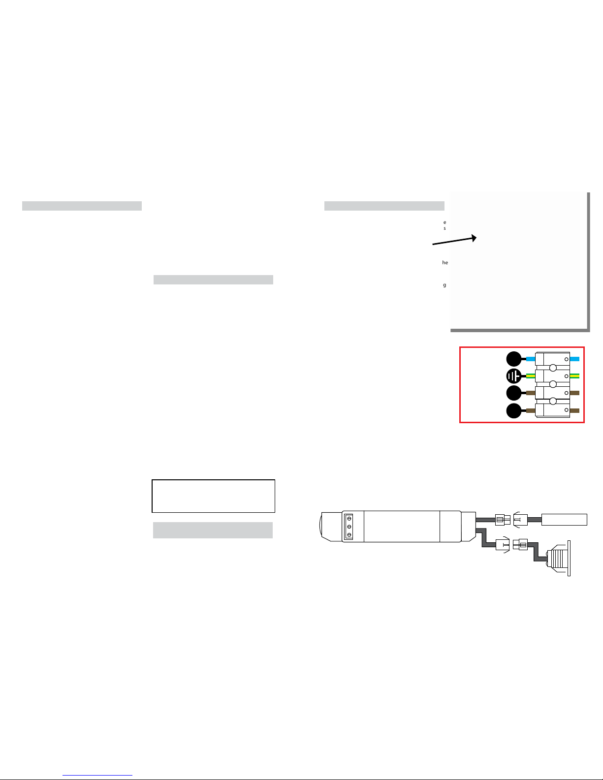
07) Make con nections into the terminal b lock
according to the following colour code:
Neutral – Blue
Earth – Gree n and Yellow
Live – Brown or Red
08) Conn ect the emergency d river to the battery and
emergency downlight and write commissioning
date on batter y. (See below for diagram).
09) Replace the centr al metal tray.
10) Restore the power supp ly and switch on.
11) Th e emergency downlight wi ll illuminate green
on normal oper ation, which indicates the t ting
is charging. On mai ns power failure the LED will
illuminate white light continuously for a minimum
of 3 hours.
L’ LN
NEUTRAL
(Blue)
SWITCHED
LIVE (Brown)
PERMANENT
LIVE (Brown)
EARTH
(Green/Yellow)
DRIVER
L
E
N
BATTERY
INPUT 220-240VAC
50/60Hz
1.4W LED
 Loading...