

Page 1
Issue 2015
Model:
DFH2KW / AC6527
2kW Adjustable Downow Heater
These instructions are provided as a guideline to assist you.
PLEASE READ THESE INSTRUCTIONS BEFORE INSTALLATION
AND RETAIN FOR FUTURE REFERENCE
Pack contents:
1 x Downow heater
1 x Fixing kit
FOR PRODUCT ADVICE:
• T: 01933 673 144
• F: 01933 678 083
• E: sales@eterna-lighting.co.uk
Visit our website:
www.eterna-lighting.co.uk
INSTALLATION INSTRUCTIONS
A guide for qualied electricians
Children of less than 3 years should be kept away from the
heater unless continuously supervised.
Children aged from 3 years and less than 8 years shall only
switch on/o the appliance provided that it has been placed
or installed in its intended normal operating position and
they have been given supervision or instruction concerning
use of the appliance in a safe way and understand the hazards involved.
Children aged from 3 years and less than 8 years shall not plug in, regulate
and clean the appliance or perform user maintenance.
WARNING!
ENERGY EFFICIENCY:
The following su ggestions will help you prot ect the
environment and s ave money on your electrici ty
bills:
Always switch heate rs o when not in use.
Using a lower thermo stat setting will reduce t he
energy used by th e heater.
CLEANING:
Clean this ttin g only with a soft dry clo th.
Do not use any chemic al or abrasive cleaners.
EVENTUALLY, YOU MAY WANT TO
REPLACE THIS PRODUCT:
Regulations require the recycling of Waste from
Electrical and Electronic Equipment (European
“WEEE Direc tive” eective August 20 05—UK
WEEE Regulation s eective 2nd January 20 07).
Environment Agenc y Registered Producer : WEE/
GA0248Q Z.
WHEN YOUR PR ODUCT COMES TO TH E END OF
ITS LIFE OR YO U CHOOSE TO REPLACE I T, PLEA SE
RECYCLE IT W HERE FACILITIES E XIST DO NOT
DISPOSE WITH HOUSEHOLD WASTE.
IF YOU EXPERIENCE PROBLEMS:
If you believe your p roduct is defective, p lease return
it to the place where yo u bought it. Our Technical
Team will gladly advise on any Eterna Lighting
product, bu t may not be able to give specic
instructions regarding individual installations.
Made in China
SOME PARTS OF THIS
PRODUCT CAN BECOME
VERY HOT AND CAUSE
BURNS. PARTICULAR
ATTENTION HAS TO BE
GIVEN WHERE CHILDREN
AND VULNERABLE
PEOPLE ARE PRESENT.
CAUTION!
Page 2
READ THIS FIRST:
This heater must b e installed in accordance with
the Building Re gulations. These may be obta ined
from OPSI or viewed and downloaded from www.
communities.go v.uk following the link for Building
Regulations.
This heater is desig ned for wall mounting and
must be used wit h the warm air vent facing
downwards. This h eater should not be used in any
other orientat ion and should not be used as a fr ee
standing portable appliance.
ADV ISO RY: This heater must b e installed at least
1.8m above the oor.
This heater must b e installed so that switches a nd
other controls (except t he pull cord) cannot be
touched by a per son in the bath or shower.
The mounting po sition should allow the free
movement of air arou nd the heater. Obstructing the
air ow could result in ove rheating.
This produc t is not intended to be used by childr en
and persons wi th sensory, physical and/or ment al
impairments th at would prevent them from using i t
saf ely.
Small children sho uld be supervised to ensu re that
they do not play with th is appliance.
Switch o the mains be fore commencing installati on
and remove the appropriate circuit fuse.
Suitable for indoor use only.
This produc t is suitable for installatio n on surfaces
with normal ammability e.g. wood, plasterboard,
masonry. It is not sui table for use on highly
ammable sur faces (e.g. polystyren e, textiles).
Before makin g xing hole(s), check that there are no
obstructi ons hidden beneath the mount ing surface
such as pipes or cab les.
The chosen loc ation of your new heater should a llow
for the produc t to be securely mounted (e.g. to a r m
wall) and safel y connected to the mains suppl y.
Do not site the heate r directly beneath a mains
outlet socket.
If the location o f your new heater requires the
provision of a new el ectrical supply, the suppl y
must conform with the requirements of the Building
Regulations.
This produc t is designed for permanent co nnection
to xed wiring: this s hould be to a suitable ring
circuit (protec ted with a 10 Amp MCB or fuse)
or a fused spur (with a 10 Amp fu se) via a fused
connection u nit. The supply must incorp orate a
switch or other me ans of disconnection.
If installed in a b athroom, the supply circuit m ust be
protected by a 30 mA RCD.
Make connecti ons to the electrical supp ly in
accordance with the f ollowing code:
Live - Brown or Red
Neutral - Blue or B lack
This produc t is double insulated, do not conn ect any
part to Ear th.
WARNING - To avoid overheating,
do not cover the heater.
The heater is t ted with 2 stage over-temperatu re
protection i n addition to the temperature co ntrol
adjustable th ermostat: for protec tion against brief
excess of temperat ure, the heater has a resettin g
thermostati c device; for longer perio ds of excess
temperature or h igher excess temperatures, t he
heater is tted w ith a one-shot thermal f use which
cannot be reset.
As you are making a xed connection to the mains ,
you are advised at e very stage of your instal lation to
double-check any electrical connections you have
made. After you h ave completed your installatio n
there are elec trical tests that should b e carried out:
these tests are sp ecied in the Wiring Reg ulations
(BS7671) refer red to in the Building Regulati ons.
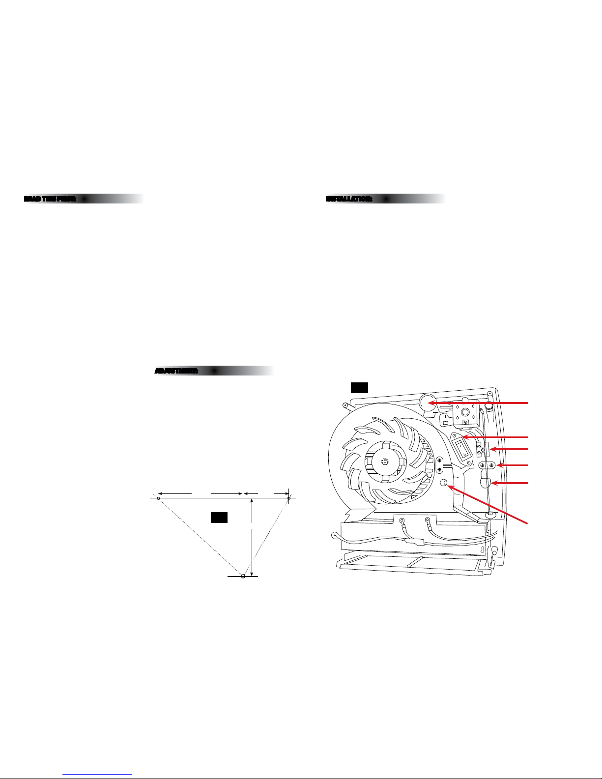
AD JUS TME NT:
1. Switch o the main power and rem ove the fuse.
2. Remove the two s crews on the front of the case
and remove the fron t cover.
3. Select the de sired mode of operation usi ng the
switch i.e:
I = 1kW xed heat
II = 2kW xed heat or 1kW variab le thermostat
controlled
4. Turn the thermostat contr ol clockwise to increase
the room temper ature and anti-clock wise to
decrease.
5. Close the front cover and s ecure using the two
screws.
INSTALLATION:
01. Choose the location for you r new heater giving
consideration to a ll of the points above.
02. Loosen the two s crews at the top of the front of
the heater and lif t o the front cover.
03. Using the guide diagr am opposite, mark the
position of the to p two xing holes.
04. Use a spirit leve l to check holes are level.
05. Make the top two xi ng holes using a suitable
drill bit.
06. Insert th e plastic plugs and screws leav ing
approximately 3mm of the shank protruding.
07. Hang the heater on the screws. If th e xings
supplied are not su itable for your mounting
surface, select suitable alternatives.
08. Mark the posi tion of the third xing hole usi ng
the heater as a templa te.
09. Remove the heater, make the x ing hole and
insert the pla stic plug.
10. Replace the heater adju sting the top two screws
to make as tight a t as possib le.
11. Secure using the th ird xing through the hole
indicated opposite.
12. Remove the cable clamp f rom inside the heater.
13. Threa d the supply cable through th e hole in the
rear of the case.
14. Make conn ections to the supply term inals
according to the colo ur code (left). Ensure that
there are no stran ds or whiskers protruding fr om
the terminals.
15. Secure t he cable under the cable cla mp. Ensure
that the cable is gr ipped rmly but take care not
to over-tighten the screw s.
16. Select the desired mode of o peration using the
switch i.e:
I = 1kW xed heat
II = 2kW xed heat or 1kW variab le thermostat
controlled
17. Set the th ermostat to the mid positio n.
18. Close and secure the f ront cover.
19. Restore the power and swi tch on.
Fig 2
Thermostat Control
1kW / 2kW Selector
Terminal Block
Cable Clamp
Fixing Hole
Cable Entry
Fig 1
Fixing Hole
Positions
124m m
67mm
114 mm
 Loading...