

Page 1
INSTALLATION INSTRUCTIONS
A guide for qualied electricians
Model:
CTIME
2kW Convector Heater With Timer
These instructions are provided as a guideline to assist you.
PLEASE READ THESE INSTRUCTIONS BEFORE INSTALLATION
AND RETAIN FOR FUTURE REFERENCE
Issue 2015
FOR PRODUCT ADVICE:
• T: 01933 673 144
• F: 01933 678 083
• E: sales@eterna-lighting.co.uk
Visit our website:
www.eterna-lighting.co.uk
Made in China
Pack contents:
1 x Convector heater with time r
c/w 13A. fused 3 pin plug tted
2 x Mounting feet
4 x Feet xing screw s
4 x Wall mounting bracke ts
4 x Wall plugs
4 x Wall xing screws
SOME PARTS OF THIS
PRODUCT CAN BECOME
VERY HOT AND CAUSE
BURNS. PARTICULAR
ATTENTION HAS TO BE
GIVEN WHERE CHILDREN
AND VULNERABLE
PEOPLE ARE PRESENT.
CAUTION!
Children of less than 3 years should be kept away from the
heater unless continuously supervised.
Children aged from 3 years and less than 8 years shall only
switch on/o the appliance provided that it has been placed
or installed in its intended normal operating position and
they have been given supervision or instruction concerning
use of the appliance in a safe way and understand the hazards involved.
Children aged from 3 years and less than 8 years shall not plug in, regulate
and clean the appliance or perform user maintenance.
WARNING!
CLEANING:
• Always remove the plug from th e electrical socket
and allow the heater to co ol down before cleaning
the heater.
• Wipe heater with a s oft dry cloth.
• Store the heater in a clea n dry place.
CLEANING WARNING:
Do not immerse the heater in
water.
Do not use any cleaning chemicals
such as detergents and abrasives.
Do not allow the interior to get
wet.
EVENTUALLY, YOU MAY WANT TO
REPLACE THIS PRODUCT:
Regulations require the recycling of Waste from
Electrical and Electronic Equipment (European
“WEEE Direc tive” eective August 20 05—UK
WEEE Regulation s eective 2nd January 20 07).
Environment Agenc y Registered Producer : WEE/
GA0248Q Z.
WHEN YOUR PR ODUCT COMES TO TH E END OF
ITS LIFE OR YO U CHOOSE TO REPLACE I T, PLEASE
RECYCLE IT W HERE FACILITIES E XIST DO NOT
DISPOSE WITH HOUSEHOLD WASTE.
IF YOU EXPERIENCE PROBLEMS:
If you believe your p roduct is defective, p lease return
it to the place where yo u bought it. Our Technical
Team will gladly advise on any Eterna Lighting
product, bu t may not be able to give specic
instructions regarding individual installations.
Page 2
x2
Back View
50cm 50cm
Base View
100cm40cm
READ THIS FIRST:
Check the pack an d make sure you have all of the par ts
listed on the fr ont of this booklet. I f not, contact the
supplier where you bought this product.
IMPORTANT SAFEGUARDS:
When using an el ectrical applian ce, basic safety
precautions should always be observed, including the
following:
If operating t he heater as a freestan ding appliance,
ensure the feet a re correctly atta ched beforehand.
This appliance i s not intended for use by pe rsons
(including children) with reduced physical, sensory
or mental capa bilities, or lack of exp erience and
knowledge, unless they have been given supervision
or instruct ion concerning use of the ap pliance by a
person responsible for their safety.
Extreme c aution is necessar y where children
or persons
with reduced physical, sensory or mental capabilities may
come into contact with the heater when in use.
The product is for household/oce use only.
WARNING -
In order to avoid
overheating do not cover or
obstruct grilles or air intake
openings when in use.
Do not place the h eater on carpets with a ve ry
deep
pile.
Always ensure that t he heater is placed on a
rm level
surface and ensure that the heater is not positioned close
to ammable materials, such as curtains, drapes etc as this
could create a re hazard.
The heater mus t not be located adjacent to o r
against
an electrical socket.
Do not run the cord u nder carpets/rugs .
Arrange the cor d away from high trac areas an d
where it will not become a trip hazard.
Keep the mains lea d away from the
heater when in use.
Do not operate t he heater with a damaged
cord/plug
or if the heater malfunctions.
If the supply cor d is damaged, it must be
replaced by a
qualied engineer.
Avoid the use of an ex tension cord as this may
overheat
and cause a risk of re.
Do not use the hea ter in any areas where
petrol, paint
or other ammable liquids or ammable fumes may be
present e.g. garages or workshops.
Do not use this hea ter in the immediate
surroundings
of a bath, shower, swimming pool or where water is
present.
This heater is hot w hen in use. To avoid burns
and
personal injury, do not let bare skin touch hot surfaces.
Never leave the hea ter unattended whils t it is
in use.
SPECIFICATION:
VOLTAGE: 220-240V ~ 50Hz
POWER MAX: 2kW
WARNING:
This produc t must only be operate d in an upright
position.
Do not try to rep air the heater yourself, always
consult a suitably qualied engineer.
OPERATIO N OF THE HEATER:
NOTE: It is norm al for the heater to smell sli ghtly for
a short whil e when turned on for the r st or after a
period of not being used.
ATTACHING THE FEET:
1. Tip heater upside d own.
2. Attach feet to eac h end of the heater using the
screws provid ed. Ax the feet using 2 scr ews
diagonally to co rrespond with the pre cu t holes.
Fasten securely.
3. Turn heater correc t way up.
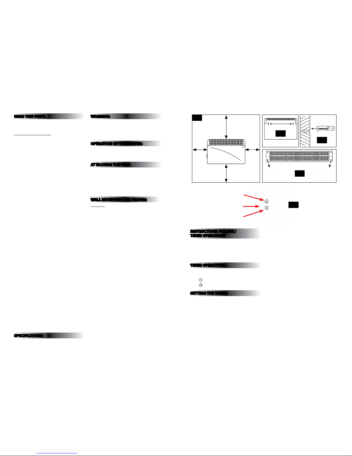
WALL MOUNTING THE HEATER:
CAUTION: The heater must b e installed away from
ammable sur faces at least 40cm be tween the lower
part of the ap pliance and the oor, 50 cm in fron t/side
and 100cm below any g iven surfaces as shown i n g.
1 opposite.
The feet must b e removed before moun ting the
appliance on the wall.
1. Measure the distance be tween the two slots
situated at the ba ck of the appliance (see g. 2).
2. Drill two holes at t he same distance in the wa ll and
insert a wall p lug in each hole.
3. Place the brackets fa cing the holes as indicat ed on
g.3 (slots up wards) and attach them in thi s position
with the screws supplied.
4. Before attach ing the appliance on the br ackets,
attach the two other brackets underneath the
appliance as indicated on g.4.
5. Attach the applian ce on the wall. To do so,
hold
it in such way that the slots are facing the brackets;
insert the appliance halfway onto the brackets until
the appliance can go down into the grooves of the
brackets.
6. As soon as the appli ance is positioned corr ectly,
take a pencil and mark a dot in the hole of each bracket
situated underneath the appliance.
7. Then remove the appliance.
8. Drill a hole in the wa ll as marked and insert a
wall
plug in each hole.
9. Attach the appliance b ack on the wall as
indicated in
point 5, insert screws through the brackets underneath
the appliance and tighten.
INSTRUCTIONS FOR USE /
TIMER OPERATION:
This model is al so tted with a 24hr timer wh ich has
96 segments around its circumference, each segment
being equiv alent to 15 minutes of time. With the ai d of
this timer it is po ssible to preset the time an d duration
of the period (s) that is desired for the heater to o perate
in any 24hr period .
TIMER OPERATION:
The centre of the ti mer has a 2 position slide s witch.
(See Fig. 5 above).
= Unit is always on
= Timer func tion is on
SETTING THE TIMER:
Ensure the slide s witch on the timer is at the clo ck
position.
Rotate the outer r ing of the timer in a clock wise
direction until the current time is lined up with the
arrow pointer, i.e. if t he time the timer is being s et is
8pm, rotate the o uter ring until the number 20 i s in line
with the arrow pointer.
Set the time the h eater is required to run by pu lling the
segments around the outer ring forward appropriate
to the running period(s) required.
When set, the h eater will operate each day d uring the
times programmed.
NOTE: The heater mus t always be plugged into a
power socket, t he element switches mu st be in the on
position and th e thermostat must be su itably set to
ensure the heater w ill come on.
If the heater is required to run continuously, the slide
switch on the tim er should be set to the “I ” position.
If it is subseque ntly required to rever t back to timer
operation, t he slide switch on the time r should be set
to the clock.
NOTE: When using in timer mode, due consideration
should be given t o the fact that the heater m ay come
on whilst unattended.
Choose a suitab le location for the hea ter, taking into
account the safe ty instructions a bove.
Insert the plug of t he heater into a suitable so cket.
Turn the thermosta t knob fully in a clock wise direction
to the maximum setting.
Turn on the heating ele ments by means of the
rocker switche s on the side panel. Whe n the heating
elements are o n the switches will illumi nate. For
maximum heat o utput both switches sho uld be on.
Example:
Switch 1 = 750W | Switch 2 = 1.25kW | Comb ined = 2kW
When the desire d room temperature has b een
reached, the thermostat knob should be turned slowly
anti-cloc kwise until the therm ostat click is heard and
the lights on the e lement switches are se en to go out.
After this the h eater will keep the air temp erature in
the room at the se t temperature by switchi ng on and
o automatically.
Fig 1
Fig 2
Fig 3
Fig 4
Slide switch
Timed
Continuous
Power
Fig 5
 Loading...