

Page 1
Model:
SQPRISMW / SQOPALMW
CIRPRISMW / CIROPALMW
IP65 LED Utility Fitting With Multi-Function Sensor
These instructions are provided as a guideline to assist you.
PLEASE READ THESE INSTRUCTIONS BEFORE INSTALLATION
AND RETAIN FOR FUTURE REFERENCE
Email: sales@eterna-lighting.co.uk / technical@eterna-lighting.co.uk
Visit our website: www.eterna-lighting.co.uk
Made in ChinaIssue 1216
Pack contents:
1 x Base
1 x Diuser
874/2012
MODELNO.
Fresh Prince Range
EVENTUALLY, YOU MAY WANT TO
REPLACE THIS PRODUCT:
Regulations require the recycling of Waste from
Electrical and Electronic Equipment (European
“WEEE Direc tive” eective August 20 05—UK
WEEE Regulation s eective 2nd January 20 07).
Environment Agenc y Registered Producer : WEE/
GA0248Q Z.
WHEN YOUR PR ODUCT COMES TO TH E END OF
ITS LIFE OR YO U CHOOSE TO REPLACE I T, PLEA SE
RECYCLE IT W HERE FACILITIES E XIST DO NOT
DISPOSE WITH HOUSEHOLD WASTE.
CLEANING:
Clean this ttin g only with a soft dry clo th.
Do not use any chemic al or abrasive cleaners.
IF YOU EXPERIENCE PROBLEMS:
If you believe your p roduct is defective, p lease return
it to the place where yo u bought it. Our Technical
Team will gladly advise on any Eterna Lighting
product, bu t may not be able to give specic
instructions regarding individual installations.
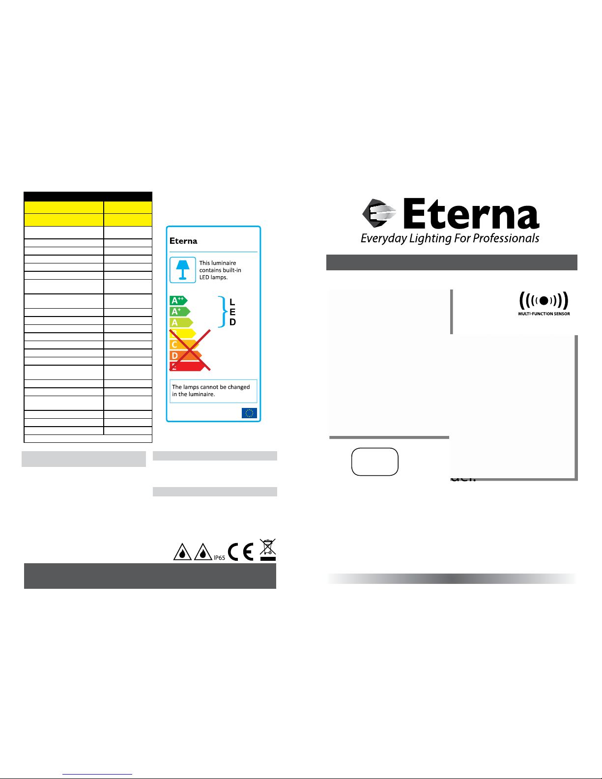
LED LAM P SPECIFICATIONS:
Luminaire lumens (opal)
1400 lm
Luminaire lumens (prismatic)
1600 lm
Lumens from chip (no diuser)
1750 lm
Rated Wattage 18W
Rated luminous ux (Opal) 1350 lm
Rated luminous ux (Prismatic) 1550 lm
Nominal life time of the lamp 35,000 hrs
Colour temperature 4000K
Number of switching cycles
before premature lamp failure
15,000
Warm-up time up to 60% of the
full light output
Instant full light
Dimmable No
LED array dimensions SQUARE (L) 215 x (H) 215mm
LED array dimensions CIRCLE 240mmØ
Nominal beam angle 120°
Rated power 18W
Rated lamp lifetime 35,000 hrs
Lamp power factor >0.9
Lumen maintenance factor at end
of nominal life
≥0.70
Starting time <0.1s
Colour rendering 80 Ra
Colour consistency
Within 6 step
Macadam ellipse
Rated peak intensity 520cd
Rated beam angle 120°
Voltage / Frequency 240V~50Hz
Not suitable for accent lighting
INSTALLATION INSTRUCTIONS
A guide for qualied electricians
Page 2
READ THIS FIRST:
Check the pack and m ake sure you have all of the
parts liste d on the front of this bookle t. If not,
contact the outlet where you bought this product.
This produc t must be installed by a compet ent
person in accord ance with the current building a nd
IEE wiring regulations.
As the buyer, install er and/or user of this product it
is your own responsi bility to ensure that this tt ing
is t for the purpo se for which you have intended
it. Eterna Lightin g cannot accept any liability fo r
loss, damage or premature failure resulting from
inappropriate use.
This product is designed and constructed according
to the principles o f the appropriate British Stan dard
and is intended fo r normal domestic ser vice. Using
this tting in any oth er environments may result in
a shortened w orking life, for example w here there
is prolonged p eriods of use or higher than no rmal
ambient temper atures such as lighting public or
shared spaces or in n ursing /care home facilities.
Switch o the mains be fore commencing installati on
and remove the appro priate circuit fuse or lock o
MCB.
Suitable for outdoor use.
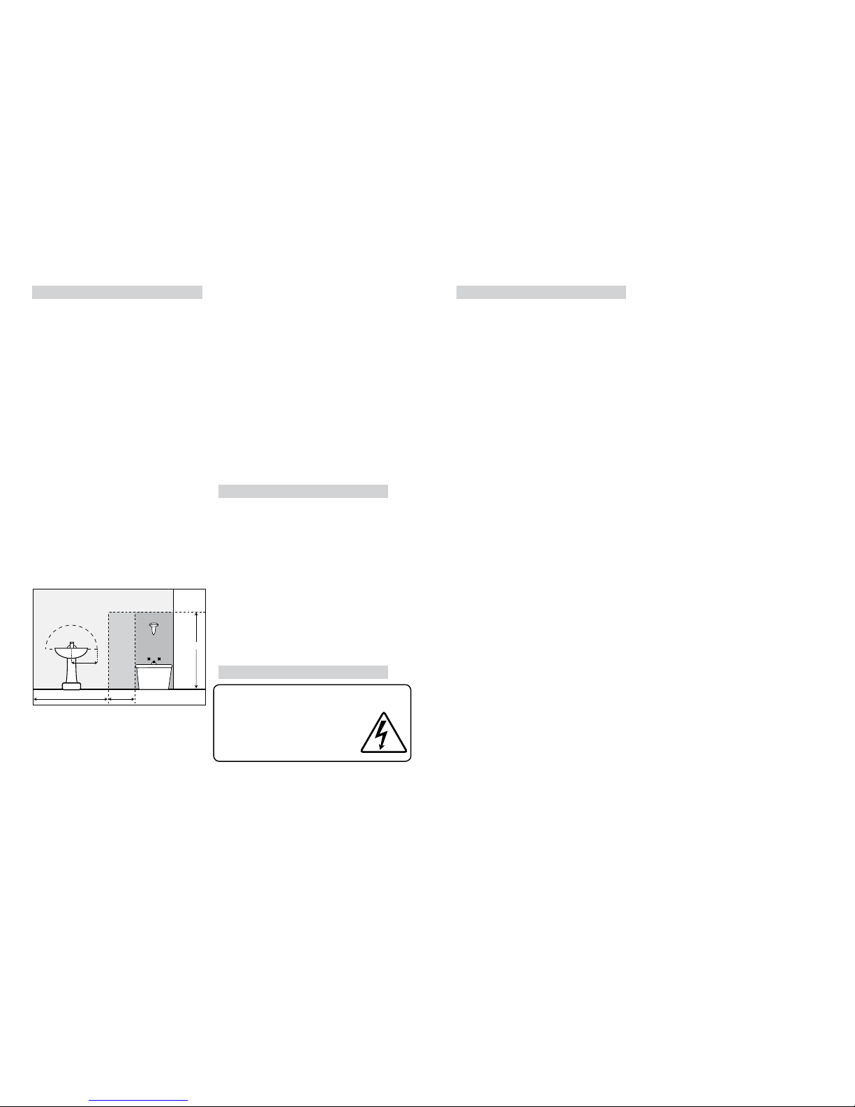
This produc t is suitable for use in living are as,
Bathroom Zone 2 an d outsides of zones.
If being t ted in a bathroom a 30 mA RCD must
be used.
This produc t is designed for permanent co nnection
to xed wiring: this m ust be a suitable circuit
(protected w ith the appropriate MCB or fuse).
This produc t is suitable for installatio n on surfaces
with normal ammability e.g. wood, plasterboard
and masonry. It is not s uitable for use on highly
ammable sur faces (e.g. polystyren e, textiles).
Before makin g xing hole(s), check that there are no
obstructi ons hidden beneath the mount ing surface
such as pipes or cab les.
The chosen loc ation of your new tting shou ld
allow for the prod uct to be securely mounte d (e.g.
to a ceiling joist) and s afely connected to the mai ns
supply (lighting circuit).
When making con nections ensure that the ter minals
are tightened se curely and that no strands of wi re
protrude. Chec k that the terminals are tightene d
onto the bared cond uctors and not onto any
insulation.
This produc t must be connected to ear th
termination.
This produc t is not intended to be used by childr en
and persons wi th sensory, physical and/or ment al
impairments th at would prevent them from using i t
saf ely.
You are advised at ever y stage of your installatio n to
double-check any electrical connections you have
made. After you h ave completed your installatio n
there are elec trical tests that should b e carried out,
these tests are sp ecied in the current IEE wir ing and
building regulations.
INTRODUCTION:
The LED utilit y light incorporates a microwave
sensing device wh ich continuously scans the
operating zon e and immediately switches th e
light on when it det ects movement in that area.
This means that whe never movement is detecte d
within the range o f the sensor the light will switch
on automaticall y and illuminate the area you have
selected to l ight. While there is movement wi thin
range of the unit th e light will remain on.
A microwave sensor is an a ctive motion detecto r
emitting high -frequency ele ctro-magnetic waves at
5.8GHz and rece iving their echo. The senso r detects
change in the echo p attern within its detec tion
zone and the light is th en triggered. The wave can
pass through doo rs, glass and thin walls and will
continually monit or the signal within the detec tion
area.
LAMP REPLACEMENT:
INSTALLATION:
Isolate mains and lo ck o.
Choose the loc ation for your new tting accor ding to
the conditions listed opposite.
01) Unscrew gear tray screw and allow the ge ar tray
to rest on its hing e.
02) Drill holes in the back of yo ur tting for your
xing screws, t ake care and drill gently to
ensure a clean hole t hrough. Use a drill bit sized
appropriately to your xing screws (not supplied).
03) Using the back of your tti ng as a template,
mark the positio n of your xing holes on your
mounting surf ace.
04) Prepare the holes i n your mounting surface as
appropriate for your xings.
05) Pierce the rubber gro mmet in the back of your
tting makin g a hole just large enough to make a
tight t around the in coming mains cable.
06) Thread the cable t hrough the grommet and oer
the tting to the ce iling / wall.
07) Secure the ttin g in place. Note, if protection
against ingress of moisture is required, the heads
of screws must be cove red with a silicone or
similar sealant.
08) Check that the gromm et is still correctly t ted in
the cable entry hole and around the incoming
cable.
09) Make the electr ical connections accordi ng to the
symbols, adj acent to the connector bloc k, Brown
to live (L) Blue to neutr al (N) and earth green &
yellow (E).
10) Set the multi-func tion sensor. (See
“understanding the controls” instructions on next
page).
11) Oer the di user and decorative trim onto th e
top of the tting a nd turn clockwise until th ey are
held securely.
12) Restore the power and switch on .
225cm
60cm240cm
60cm
radius
from tap
ZONE 1
ZONE 0
ZONE 2
ZONE 2
Bathroom Zones Diagram
The light source cont ained in this luminaire
shall only be rep laced by the manufacturer,
service age nt or a similar qualied pers on.
CAUTION, RISK OF ELECTRIC SHOCK.
The light source is designed to last the lifetime of the
luminaire.
Page 3

MULTIFUNCTION SENSOR
SPECIFICATIONS:
UNDERSTANDING THE CONTROLS:
Refer to the tabl e (g. 1) below.
The sensor is an ac tive motion detector : it emits a
high frequenc y electromagneti c wave 5.8GHz and
receives its ech o. The sensor detects th e change
in echo from movem ent in its detection zone . A
microprocesso r then triggers the switch li ght ON
command. Detection is possible through doors,
panels of glass and t hin walls.
DETECTION AREA:
This determine s the eective range of the m otion
detector and i s set up by DIP switches at the sens or,
refer to g. 2 opp osite. Note that reducing the
sensitivity will also narrow the detection range.
The following settings are available:
I - Detection R ange 100%
II - Detectio n Range 75%
III - Detecti on Range 50%
IV - Detectio n Range 10%
HOLD TI ME:
This determine s the time the tting remains at
100% level on motion d etection and is set with DI P
switches at the se nsor, refer to g. 2 opposite. The
walk test sett ing is useful when installi ng the tting
to establish correct operation and range.
The following settings are available:
I - Walk test mode 5s
II - 90s
III - 3 minutes
IV - 10 minutes
DAYLIGHT SE NSOR:
This setting h olds o the 100% light output sho uld
there be sucien t daylight and is set using DIP
switches at the se nsor, refer to g. 2 opposite.
The following settings are available:
I - Photocell disabl ed
II - 50 lux twilight o peration
III - 15 lux twilight ope ration
IV - 5 lux darknes s operation only
* In daylight sett ing the lamp(s) will always be on
with motion dete cted and operate at 100% light
output, even in br ight daylight.
CORRIDOR FUNCTION:
This setting determines how long the tting should
operate at 10% output a fter the hold time has
elapsed and is se t by DIP switching at the sensor,
refer to g. 2 opp osite.
NOTE: Setting at 0 s disables this function; s etting
at +
∞
leaves it permane ntly at 10% output until
activated again.
The following settings are available:
I - 0s
II - 30s
III - 10 minutes
IV - +
∞
Detection Area Hold Time Daylight Sensor Corridor Function
1 2 3 4 5 6 7 8
I ON ON 100% I ON ON 5s I ON ON
Disable
I ON ON 0s
II - ON 75% II - ON 90s II - ON 50Lux II - ON 30s
III ON - 50% III ON - 3min III ON - 15Lux III ON - 10min
IV - - 10% IV - - 10min IV - - 5Lux IV - -
+
∞
ON
OFF
Model number MLC16 C-P
Operating voltage 220-240Vac, 50/60Hz
Output constant current
300mA / 350mA, s et via DIP
switch
Output voltage 28 -48Vdc
Eciency ≥80%
Power fac tor ≥0.9
HF system
5.8GHz ± 75MHz, ISM wave
band
Transmitting power <0.5mW
Detection z one max. 16m (D) x 6m (H)
Dectection sensitivit y 10% / 50% / 75% / 100%
Hold time 5s / 90s / 3 min / 10 min
Corridor function 0s / 30s / 10 min / Disable
Daylight sensor 5lux / 15lux / 50lux / Disable
Standby dimming level 10% - can be customised
Mounting height 6m Max.
Motion detection 0.5~3m/s
Detection angle
150° (wall installation)
360° (ceiling insta llation)
Fig 1
Detection
Area
Daylight
Sensor
Hold
Time
Daylight
Sensor
Corridor
function
Fig 2
RED DIRECTIVE Eterna Lighting Ltd
Microwave Occupancy Sensor
Full declaration available at www.eterna-lighting.co.uk
 Loading...