

Page 1
Model:
CF28PIR
Flush Ceiling Fitting with Integral PIR Detector
These instructions are provided as a guideline to assist you.
PLEASE READ THESE INSTRUCTIONS BEFORE INSTALLATION
AND RETAIN FOR FUTURE REFERENCE
Pack contents:
1 x Flush tting with Integral PIR
1 x GR10q 4 pin DD 28W lamp
INSTALLATION INSTRUCTIONS
A guide for qualied electricians
Issue 2014
FOR PRODUCT ADVICE:
• T: 01933 673 144
• F: 01933 678 083
• E: [email protected]
Visit our website:
www.eterna-lighting.co.uk
EVENTUALLY, YOU MAY WANT TO
REPLACE THIS PRODUCT:
Regulations require the recycling of Waste from
Electrical and Electronic Equipment (European
“WEEE Direc tive” eective August 20 05—UK
WEEE Regulation s eective 2nd January 20 07).
Environment Agenc y Registered Producer : WEE/
GA0248Q Z.
WHEN YOUR PR ODUCT COMES TO TH E END OF
ITS LIFE OR YO U CHOOSE TO REPLACE I T, PLEASE
RECYCLE IT W HERE FACILITIES E XIST DO NOT
DISPOSE WITH HOUSEHOLD WASTE.
CLEANING:
Disconnect t he power and clean the exte rior only of
this tting wit h a moist (not wet) cloth.
Do not use any chemic al or abrasive cleaners.
IF YOU EXPERIENCE PROBLEMS:
If you believe your p roduct is defective, p lease return
it to the place where yo u bought it. Our Technical
Team will gladly advise on any Eterna Lighting
product, bu t may not be able to give specic
instructions regarding individual installations.
For breakage inf ormation visit:
www.eterna-lighting.co.uk
874/2012
A
MODELNO.
CF28PIR
MODELNO.
A
++
XXX kWh/1000h
30.80
CF28PIR
A
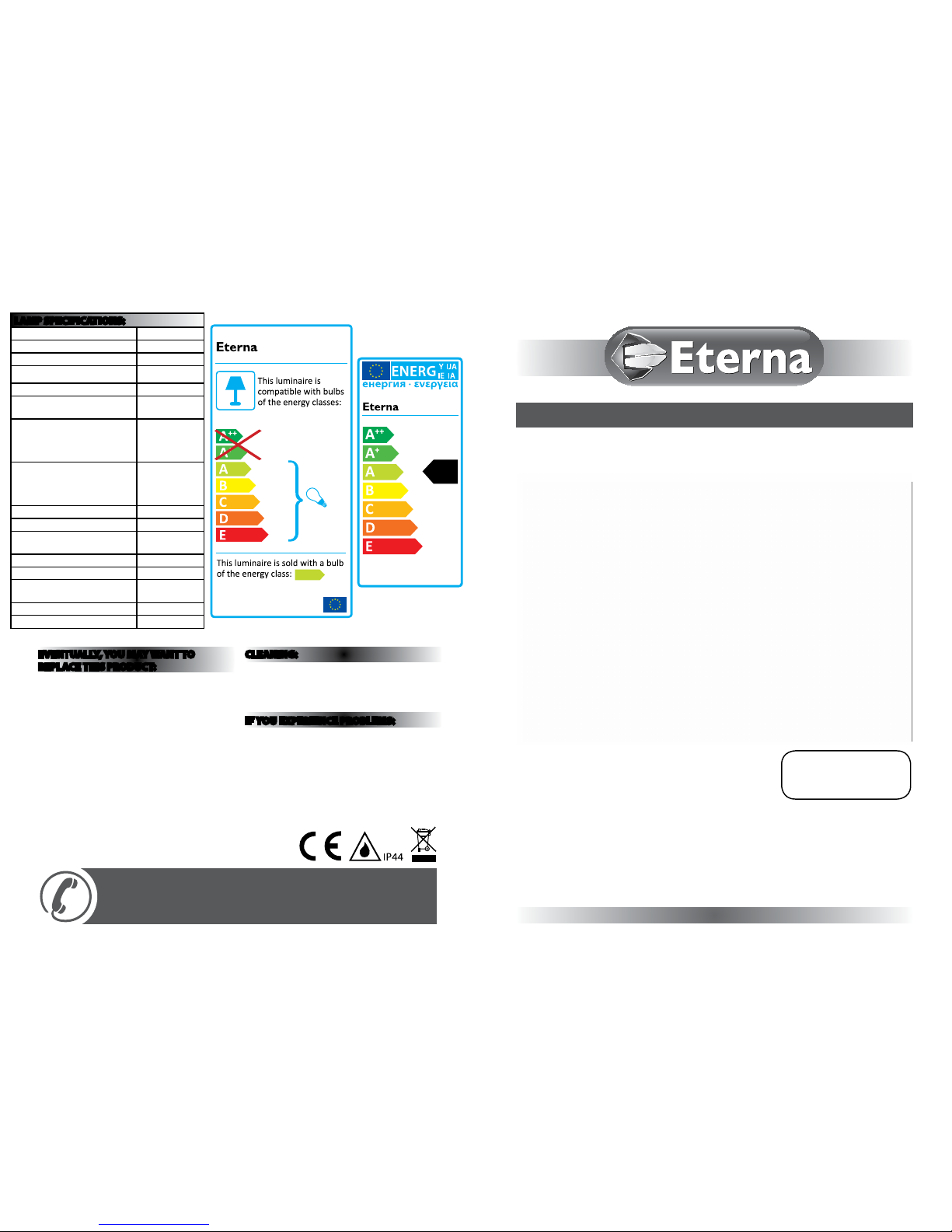
LAMP SPECIFICATIONS:
Nominal Wattage 28W
Rated Wattage 28W
Average lifetime hours 8,000 hrs
Nominal useful luminous ux
2050 lm
Rated luminous ux 2050 lm
Luminous ecacy (Lm/W) in
50Hz operation
73
Rated lamp Lumen
maintenance
2000hrs: ≥85%
4000 hrs: ≥78%
6000 hrs: ≥76%
8000 hrs: ≥75%
Rated survival factors
2000hrs: ≥98%
4000 hrs: ≥90%
6000 hrs: ≥88%
8000 hrs: ≥50%
Lamp dimensions mm 205 x 207mm
Cap type GR10q 4 Pin
Lamp Mercury content to an
accuracy of 0.1mg
<2.5mg
Colour rendering index Ra ≥80
Colour temperature 3500K
Ambient temperature required to
achieve maximum luminous ux
25°C
Dimmable No
Ballast EEI A2
Page 2
READ THIS FIRST:
Check the pack an d make sure you have all of the par ts
listed on the fr ont of this booklet. I f not, contact the
outlet where you bought this product.
This produc t contains glass, care mus t be taken when
assembling, tting or handling to prevent personal
injury or dama ge to the product.
This light tting must be installed by a competent
person in accordance with the Building Regulations
making refe rence to the current editio n of the IEE Wiring
Regulations (B S7671). The Building Regulati ons may be
obtained fr om OPSI or viewed and downl oaded from
www.communities.gov.uk following the link for Building
Regulations.
As the buyer, insta ller and/or user of this prod uct it is
your own respons ibility to ensure that thi s tting is t
for the purpos e for which you have intended i t. Eterna
Lighting canno t accept any liability for l oss, damage or
premature failure resulting from inappropriate use.
This product is designed and constructed according
to the principles of the appropriate British Standard
and is intended for normal domestic service. Using
this tting in any other environments may result in a
shortened working life, for example where there are
prolonged periods of use or higher than normal ambient
temperature s such as lighting public or sh ared spaces or
in nursing / care h ome facilities.
The lamp suppli ed with this tting is a con sumable part
and therefore may be outside of any warranty oered.
Switch o the mains b efore commencing inst allation
and remove the appropriate circuit fuse.
When workin g at heights, please use a s uitable platform .
Disconnec t the tting from the el ectrical supply b efore
ash or high volta ge testing.
Suitable for indoor use only.
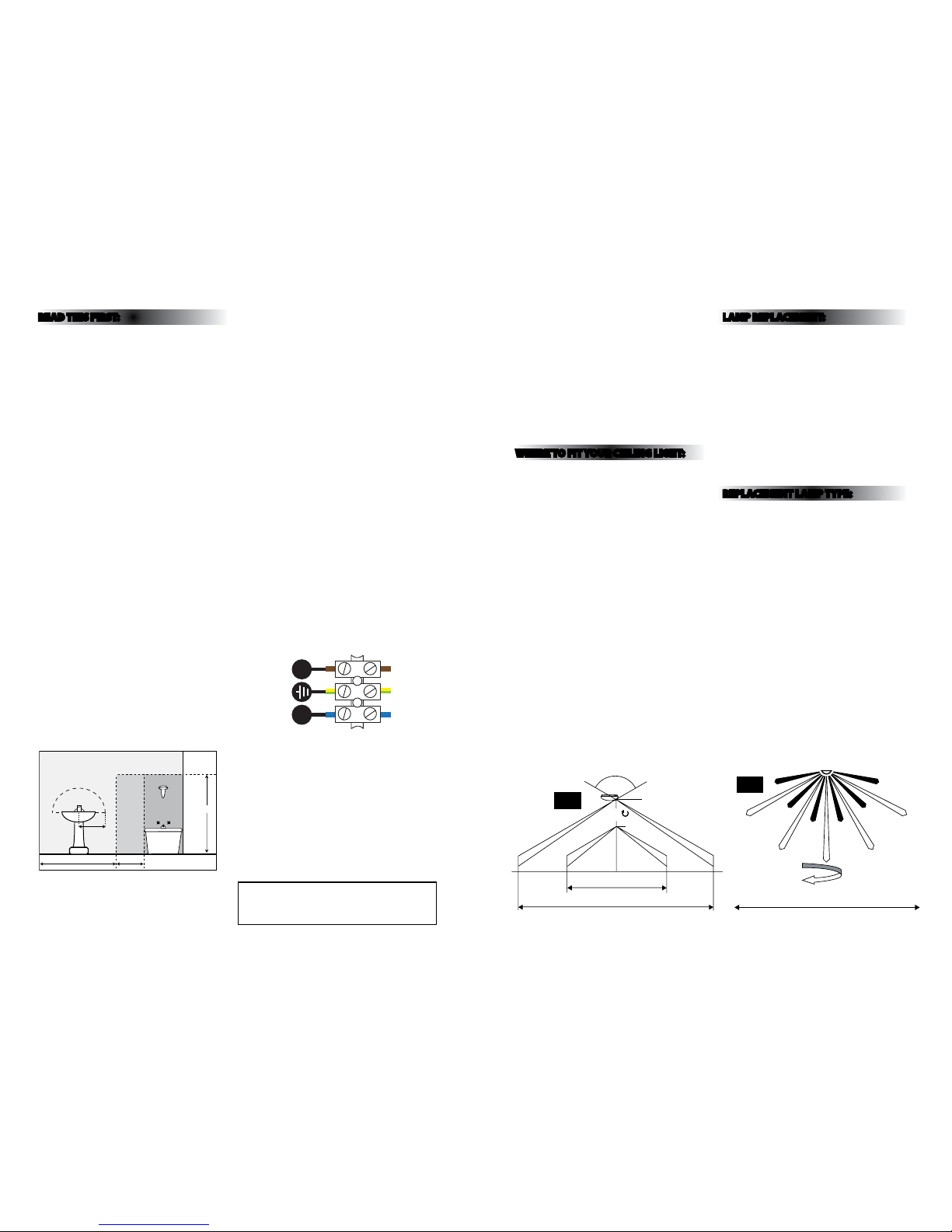
This produc t is suitable for use in liv ing areas, and
Bathroom zon e 2 and dry (Outside) zones o nly (see
diagram below a nd current IEE Wiring Re gulations for
details). If being tted in a bathroom a 30m A RCD must
be used.
This produc t is suitable for instal lation on surfaces wi th
normal ammab ility e.g. wood, plas terboard, masonr y.
It is not suitabl e for use on highly ammab le surfaces
(e.g. polystyrene, textiles).
Before maki ng xing hole(s), check that the re are no
obstructions hidden beneath the mounting surface such
as pipes or cabl es.
The chosen location of your new tting should allow
for the produc t to be securely mounte d (e.g. to a ceiling
joist) and safe ly connected to the mai ns supply (lighting
circuit).
If the locatio n of your new tting requ ires the provision
of a new elect rical supply, the supply mus t conform
with the requirements of the Building Regulations
making refe rence to the current editio n of the IEE Wiring
Regulations (BS7671).
This produc t is designed for perma nent connection to
xed wiring: thi s should be either a suita ble lighting
circuit (prote cted with a 5 or 6 Amp MCB or fus e) or a
fused spur (with a 3 A mp fuse) via a fused connec tion
unit. We recomme nd that the supply incorp orates a
switch for ease o f operation.
Make connect ions to the electric al supply in accordance
with the follow ing code:
Live - Brown or Red
Neutral - Blue o r Black
Earth - Gree n and Yellow
Where this pro duct is used to replace an e xisting light
tting, it wi ll be necessary to remo ve any existing ceiling
rose to allow clear ance for installation . If this is the case,
carefully no te the existing positi on of each set of wires
(see diagram be low). Where more than a single s et of
L, N and E wires ex ist these must be trans ferred to a
separate approved junction box or terminal block (not
supplied) wh ich must be insulated and pl aced within
the ceiling.
Additional re d wires may be present in your ce iling
that are connec ted to the ring live circuit . Do not
connect your tting to these wires. I f these wires are
not terminated i n a ceiling rose, join them tog ether in a
separate term inal block (not supplied ) and place in the
ceiling.
When making co nnections, ensure th at the terminals are
tightened se curely and that no strand s of wire protrude.
Check that the ter minals are tightened onto t he bared
conductors and not onto any insulation. Wrap loose
terminal blo cks well with insulating t ape.
This produc t must be connected to E arth.
NOTE: Very frequent switching can shorten the life of
the lamp . To minimise this , it is suggested to increas e
the time to the maximum setting.
The bulkhea d light (PIR version) incorpo rates a passive
infra red sensing device which continuously scans a
preset operating zone and immediately switches the
lamp on when it de tects movement in that a rea. While
there is movemen t within range of the unit th e lamp will
remain on.
You are advised at ever y stage of your insta llation to
double-check any electrical connections you have made.
After you have comp leted your installati on there are
electric al tests that should be c arried out: these tes ts are
specied in t he Wiring Regulations ( BS7671) referred to
in the Building Regulations.
WHERE TO F IT YOUR CEIL ING LIGHT:
To achieve best result s, we suggest you take into acco unt
the following points:
• For maximum detecti on range, the bulkhea d light
should be moun ted 1.8 to 2.5 meters (6 to 8f t) above
the area to be scan ned. (see FIG. 1 below).
• To avoid nuisance triggering, the sensor should be
directed away f rom heat sources such as hea ters/
radiators, air-conditioning outlets, other lighting, pet
entry/exit or sleeping areas etc.
• To avoid nuisance triggering, do not connect to the
same circuit as large uorescent light ttings, bathroom
fans or other so urces of mains borne noise ( peaks and
spike s).
• The PIR Sensor scanning s pecications (approx imately
8 meters at appr ox. 120° - horizontal) may vary s lightly
depending on the mounting height and location.
The detect ion range of the unit may also a lter with
temperature c hange. Before selec ting a place to install
your new ttin g you should note that moveme nt across
the scan area is mo re eective than movem ent directly
toward or away from t he sensor. If movement is made
walking dire ctly towards or away from th e sensor
and not across, th e apparent detecti on range will be
substantiall y reduced. (see FIG. 2 be low).
LAMP REPLACEMENT:
1. Switch o the elec tricity at the mains.
2. Turn the three clips outwards to remove the diuser.
3. Pull the lamp str aight out of the gear tray insi de.
4. Press the new lamp into posit ion, take care to positio n
the lamp correctly over the lampholder.
5. Replace the diuser, take ca re to position the inside
rim of the dius er over the circumference of t he rear
half of the tt ing and the soft seal aro und the hole in
the diuser ove r the PIR detector lens.
6. Press the diuser in position and turn the three clips
to retain.
7. Restore the power and sw itch on.
REPLACEMENT LAMP TYPE:
Requires 1 x 28W GR10q 4pin D D CFL lamp (included).
Eterna replacement lamp product code: DD28435.
Fitting is rate d at 28W max.
225cm
60cm240cm
60cm
radius
from tap
ZONE 1
ZONE 0
ZONE 2
ZONE 2
Bathroom Zones Diagram
3.5m
120º
2.5m
360º
6m
12m
3.5m
120º
2.5m
360º
6m
12m
360º
12m
Fig 1
Fig 2
LN
Yellow/Green
(Power Cable)
Blue
(Power Cable)
Brown
(Power Cable)
Yellow/Green
(Lamp Wire)
Blue (PIR Wire)
Brown (PIR Wire)
Page 3
INSTALLATION:
01. Choose the loc ation for your new tti ng according to
each of the condit ions above.
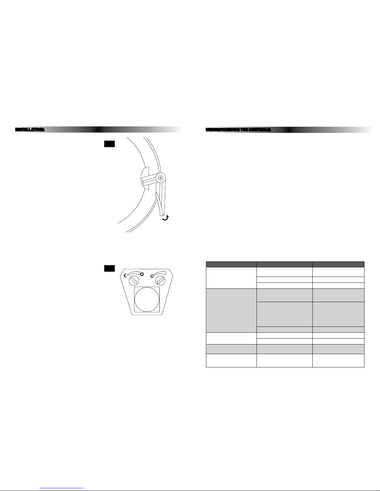
02. Turn out the thre e clips at the side of the diu ser and
lift o. (see FIG . 3 opposite).
03. Remove th e tube from the tting b y pulling straight
up.
04. Und o the gear tray retaining s crew next to the PIR
detector mo dule on the gear tray.
05. Undo the s crews at each end of the hing e and lift o
the gear tray – take c are not to lose the screws and
washers.
06. Cho ose whether you need to u se 2 or 4 screw holes
and clear throu gh using a 4-5mm diameter dr ill.
07. Using the back of the t ting as a template, mark
the position of t he xing screws on your mo unting
surface.
08. Prepare your xing holes as appropriate.
09. Pierce the c able entry gland mak ing a hole just large
enough for the c able to pass through and so t hat the
gland makes a tight seal around it.
10. Thread your suppl y cable through the glan d.
11. Secure the back of your n ew tting using suitab le
xings (not supplied).
12. Fix the gear tr ay by the hinge only, back into the
tting using the screws and washers removed earlier.
13. Allow the gear try to ha ng open.
14. Make the ele ctrical connect ions according to the
colour code above.
15. Close the gear t ray and secure with the scr ew
removed earlier.
16. Re-t t he lamp pressing rmly ont o the lampholder.
Take care to position the l amp correctly.
17. Replace the diuser, take ca re to position the inside
rim of the dius er over the circumference of t he rear
half of the tt ing and the soft seal aro und the hole in
the diuser ove r the PIR detector lens.
18. Restore the powe r and switch on.
Adjusting the duration time:
The length of ti me that the light remains on af ter
activatio n can be adjusted from 8(±2) s econds to 7(±2)
minutes. Turning the T IME control anti-clo ckwise will
reduce the duration time.
Note: Once the lig ht has been triggered by t he PIR
sensor any subse quent detection wi ll start the timed
period again from the beginning.
Adjusting t he LUX level:
Refer to FIG. 4 opposite.
The Lux control m odule has a built-in sensin g device
(photocell) th at detects daylight an d darkness. With the
control set to the () posi tion, the light will oper ate in
both daylight an d darkness. With the cont rol set to the
() position, the l ight will only operate in d arkness.
Setting the controls:
1. Turn the Lux control to t he () position, turn the mains
power on and wait h alf a minute for the control ci rcuit
to stabilize.
2. Turn the TIM E control to the minimum durati on time
(fully anti- clockwise) positio n. The bulkhead light w ill
now switch on and r emain on for about 8 secon ds.
3. Walk across t he detection area to ch eck that the
desired detection area is covered.
4. Adjust time control to the required setting.
5. To set the Lux leve l at which the lamp will
automaticall y switch “on” at night, please tu rn the LUX
control from day light to night. If the lamp is re quired
to switch on earli er, e.g. at dusk, wait for the de sired
ambient light le vel, then slowly turn the LUX con trol
knob towards th e daylight setting () while so meone
walks across t he center of the area to be dete cted.
When the lamp sw itches on, release the Lu x control.
Important:
To avoid dust build-up and ensure proper
functioni ng of the PIR detector, peri odically wipe
the sensor len s lightly with a damp cloth.
Specication:
Voltage: 220-240 V 50 Hz
Load: Max. 28W CFL
Detection range: Approx.120
o
(horizontal),
Max. 8 metres
Duration time: From 8(±2) seconds to
7(±2) minutes adjustable
LUX control l evel: From daylight (200 0 Lux) to
darkness (<3 Lux) adjust able
Splash-proof: IP44
Protection: Class I / Earthe d
UNDERSTANDING THE CONTROLS:
PROBLEM POSSIBLE CAUSE TROUBLE SHOOT
Lamp does not switch on when
there is movement in the detection
area
1. No mains voltage Check all connections, fuses &
switches
Relocate the tting
2. Nearby lighting is too bright
Check adjustment of controls
3. Controls set incorrectly
Lamp switches on for no apparent
reason (false triggering)
1. Heat sources such as air con vents,
heater vents, other lighting or pets
are activating the sensor
Relocate the tting away from heat
sources
2. Interference from on/o switching
of electric fans, lights or appliances
on the same circuit. (This does not
always occur but a faulty switch or
noisy uorescent light may cause the
light to switch on)
Replace the faulty switch, replace
noisy uorescent tubes/starters or
connect to a separate supply circuit
3. Reection from a reective surface Relocate the tting
Light remains on
1. Continuously false triggered See above
2. Time is set too long Adjust the TIME control
Light switches on during daylight
hours
1. Lux control is set to daylight position Adjust the LUX control
When setting controls in daylight
the detection distance becomes
shorter
1. Interference by reected sunlight Re-test at night or in lower light
Fig 3
Fig 4
 Loading...