

Page 1
Model:
BULKLED / BULKLEDPC / BULKLEDMW
11W IP65 LED Bulkhead / With Photocell / With Microwave Sensor
These instructions are provided as a guideline to assist you.
PLEASE READ THESE INSTRUCTIONS BEFORE INSTALLATION
AND RETAIN FOR FUTURE REFERENCE
INSTALLATION INSTRUCTIONS
A guide for qualied electricians
874/2012
MODELNO.
BULKLED/PC/MW
EVENTUALLY, YOU MAY WANT TO
REPLACE THIS PRODUCT:
Regulations require the recycling of Waste from
Electrical and Electronic Equipment (European
“WEEE Direc tive” eective August 20 05—UK
WEEE Regulation s eective 2nd January 20 07).
Environment Agenc y Registered Producer : WEE/
GA0248Q Z.
WHEN YOUR PR ODUCT COMES TO TH E END OF
ITS LIFE OR YO U CHOOSE TO REPLACE I T, PLEASE
RECYCLE IT W HERE FACILITIES E XIST DO NOT
DISPOSE WITH HOUSEHOLD WASTE.
CLEANING:
Clean this light t ting only with a soft dr y cloth.
Do not use any chemic al or abrasive cleaners.
IF YOU EXPERIENCE PROBLEMS:
If you believe your p roduct is defective, p lease return
it to the place where yo u bought it. Our Technical
Team will gladly advise on any Eterna Lighting
product, bu t may not be able to give specic
instructions regarding individual installations.
Photocell
version
shown
Pack contents:
1 x 11W LED bulkhea d
1 x Fixing kit
1 x TRS gland
LED LAM P SPECIFICATIONS:
Lumens total ux
900 lm
Rated Wattage 11.2W
Rated luminous ux 900 lm
Nominal life time of the lamp 30,000 hrs
Colour temperature 6500K
Number of switching cycles
before premature lamp
failure
≥15,000
Warm-up time up to 60 % of
the full light output
Instant full light
Dimmable No
Nominal beam angle 120°
Rated power 11.2W
Rated lamp lifetime 30,000 hrs
Lamp power factor >0.5
Lumen maintenance factor at
end of nominal life
>80%
Starting time <0.5s
Colour rendering ≥80
Colour consistency
Within 6 step
Macadam ellipse
Rated peak intensity 230cd
Rated beam angle 120°
Voltage 240V
Not suitable for accent lighting
Email: sales@eterna-lighting.co.uk / technical@eterna-lighting.co.uk
Visit our website: www.eterna-lighting.co.uk
Made in ChinaIssue 1117
Antenna
Module
Daylight
Sensor
Daylight
-
Time
5 sec - 12 min
Sensitivity
10-10 0%
BULKLEDMW
Microwave
Sensor
L
L1
N
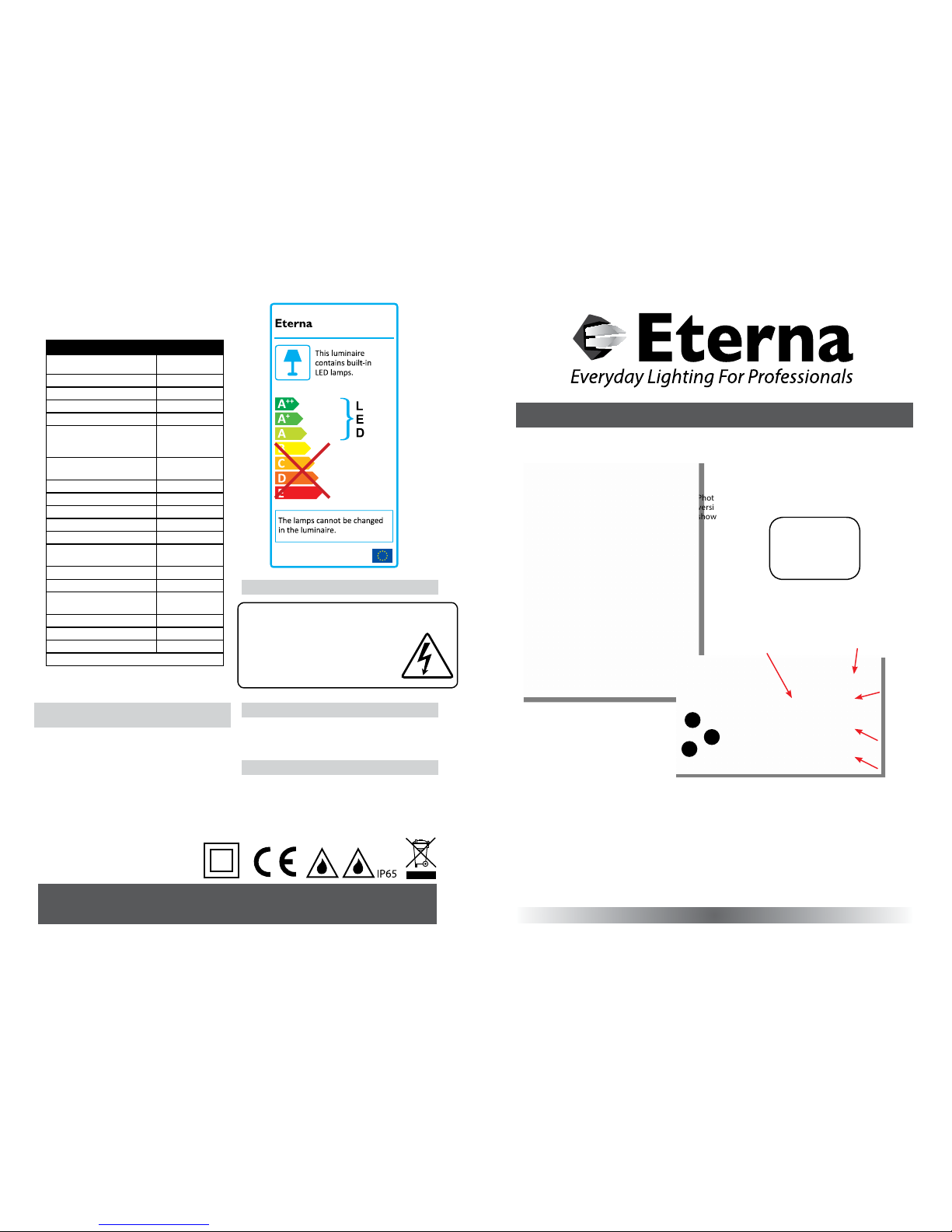
The light source cont ained in this luminaire
shall only be rep laced by the manufacturer,
service age nt or a similar qualied pers on.
CAUTION, RISK OF ELECTRIC SHOCK.
The light source is designed to last the lifetime of the
luminaire.
LAMP REPLACEMENT:
Page 2
READ THIS FIRST:
Check the pack and m ake sure you have all of the
parts liste d on the front of this bookle t. If not,
contact the outlet where you bought this product.
This produc t must be installed by a compet ent
person in accord ance with the current building a nd
IEE wiring regulations.
As the buyer, install er and/or user of this product it
is your own responsi bility to ensure that this tt ing
is t for the purpo se for which you have intended
it. Eterna Lightin g cannot accept any liability fo r
loss, damage or premature failure resulting from
inappropriate use.
This product is designed and constructed according
to the principles o f the appropriate British Stan dard
and is intended fo r normal domestic ser vice. Using
this tting in any oth er environments may result in a
shortened working life
Switch o the mains be fore commencing installati on
and remove the appro priate circuit fuse or lock o
MCB.
This unit is suitab le for outdoor use.
This produc t is designed for permanent co nnection
to xed wiring: this m ust be a suitable circuit
(protected w ith the appropriate MCB or fuse).
This produc t is suitable for installatio n on surfaces
with normal ammability e.g. wood, plasterboard
and masonry. It is not s uitable for use on highly
ammable sur faces (e.g. polystyren e, textiles).
Before makin g xing hole(s), check that there are no
obstructi ons hidden beneath the mount ing surface
such as pipes or cab les.
The chosen loc ation of your new tting shou ld allow
for the produc t to be securely mounted and s afely
connected to th e mains supply (lighting circuit).
When making con nections ensure that the ter minals
are tightened se curely and that no strands of wi re
protrude. Chec k that the terminals are tightene d
onto the bared cond uctors and not onto any
insulation.
This tting is d ouble insulated; do not connec t any
part to eart h.
This produc t is not intended to be used by childr en
and persons wi th sensory, physical and/or ment al
impairments th at would prevent them from using i t
saf ely.
IMPOR TANT: ALWAYS SWITCH O FF CIRCUIT
BEFOR E COMMENCI NG INSTALLATION O R
MAINTENANCE.
You are advised at ever y stage of your installatio n to
double-check any electrical connections you have
made. After you h ave completed your installatio n
there are elec trical tests that should b e carried out,
these tests are sp ecied in the current IEE wir ing and
building regulations.
PHOTOCELL VERSIO N:
Do not install un der eaves or in a location of freq uent
shadow that will pre vent the light from switching o
when required . Do not install near other so urces of
bright light that wil l prevent the light from switchin g
on when the ambie nt light level falls.
INSTALLATION:
IMPORTANT: Fitting must be i nstalled vertically w ith
black diuser h ousing at top. (See g.1 opposite).
01) Choose the loc ation for your new light tting
giving consideration to the points listed opposite.
02) To access the ttin g, remove the four retaining
screws and lower th e hinged diuser.
03) Drill ou t four xing holes in the back o f the tting,
according to your chos en xing method. All four
blind holes are p re-cast within the fe et bosses.
This enables th e tting to be mounted secur ely to
a solid surfa ce.
04) Cho ose the point for cable entr y and remove
(with care) the corresp onding cable entry usin g
a 20mm. hole saw. (See g .2 opposite). DO NOT
USE A HAMMER .
05) Using th e tting as a template, mark the
location of your xing holes on the mounting
surface.
06) Se cure the tting into positio n using suitable
screws and washer s (xings not supplied).
07) Cover the h eads of the screws with silicone
sealant (not supplie d), to maintain IP rating.
08) Ins ert an IP rated grommet or an I P65 cable gland
and lock into posit ion.
09) Thr ead the supply cable into the t ting. If entry is
in the rear of the t ting, there is a pre-cas t cable
groove so the wire ca n be routed to the cable
entry hole.
10) Restra in cable using the cable clamp a nd make
electrical connections.
11) R e-ax diuser and tighte n the four screws
taking care no t to over tighten, as this may
damage the unit.
12) Restore power and switch on .
BULKLED
The tting sh ould light when switched on .
BULKLEDPC
The tting wi ll light when the power has been
restored and th e ambient light level falls below t he
preset thresho ld on the photocell (note this unit is
not adjustable).
BULKLE DMW UNDERSTANDING THE
SETTI NGS: SEE PG 1 FOR MW DIAGRA M
Bulkhead mou nting height 2.5m
SENSITIVITY / DETECTING
Turn the screw completely anti-clockwise direction
to select mini mum detection distance (app rox 1m
radius), and turn sensit ivity screw completely i n a
clockwise d irection to select th e maximum detection
distance (approx 10m radi us).
TIME SETTINGS
The light can be se t to stay ON for any period of time
between ap prox 5sec (dial screw turned fully a nticlockwise) and a m aximum of 12min (dial turned fully
clockwise). Any movem ent detected during the “on”
time will reset th e timer.
The LED indicator w ill ash when adjusting the tim e
setting dial.
The number of as hes means the following:
NOTE: after the light s witches o, it takes approx
1 sec before it is a ble to start detecti ng movement
again. The light w ill only switch on in response to
movement once this p eriod has elapsed.
LUX CONTROL SETTING
Turn the Lux setting sc rew fully anti-clock wise to
select dusk to - dawn operation at approx 2 Lu x.
Turn the Lux screw fully clo ckwise to select dayl ight
operation at ap prox 2000lux.
SETTI NG THE UP THE FI TTING
Turn the Lux setting sc rew fully clockwise so t ting
will work in daylight , and set the time screw to
minimum setti ng you can then carry out th e walk
test when adjus ting the sensitivity/detec tion screw
for the require d detection area, once set y ou can
re-adjust th e Lux /time screw to the desired se tting.
MICROWAVE SENSOR TECHNICAL
SPECIFICATIONS:
Power Supply 220-240Vac
Power Fre quency 50/60Hz
Hf System 5.8GHz CW Rad ar, ISM Band
Transmission Power <10mW
Rated Load: 1200W Max.
Detection Angle 360°
Reach: 1-10m (Radii.), Adjustable
Time Setti ng 5 Sec to 12 Min
Light Control 2~2000LUX
Fig 1
Drill knock- out using
a 20mm hole saw
DO NOT USE A HAMM ER!
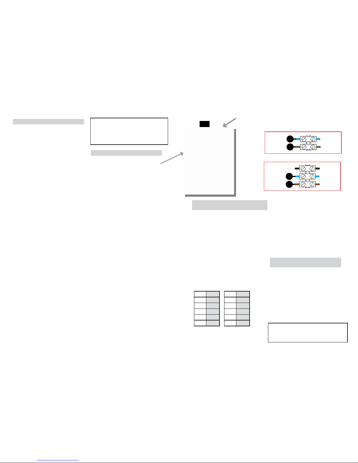
BULKLED / BULKLEDMW
BULKLEDPC
LN
Blue
(Power Cable)
Brown
(Power Cable)
Blue
(Power Cable)
Brown
(Power Cable)
LN
Blue
(Power Cable)
Brown
(Power Cable)
Blue
(Power Cable)
Brown
(Power Cable)
DO NOT USE
PHOTOCELL
Flashes Time Flashes Time
1 5 secs 6 4 mins
2 15 secs 7 6 mins
3 30 secs 8 8 mins
4 60 secs 9 10 mins
5 2 mins 10 12 mins
RED DIRECTIVE Eterna Lighting Ltd
Microwave Occupancy Sensor
Full declaration available at www.eterna-lighting.co.uk
 Loading...