


DSC2P 903 ver. F
Digital position controllers
Digital position controllers
DSCxx
HEADQUARTERS
SWITZERLAND
ETEL S.A.
Zone industrielle
CH-2112 Môtiers
Phone : +41 (0)32 862 01 23
Fax : +41 (0)32 862 01 01
E-mail : etel@etel.ch
http://www.etel.ch
Copyright ETEL SA. All rights reserved. Reproduction, adaptation or translation of this document is prohibited without prior written permission.
ETEL SA makes no warranty for the use of its products and assume no responsibility for any errors which may appear in this document.
Operation &
Software Manual
AMERICAS
ETEL Inc.
333 E. State Parkway,
US - Schaumburg
IL 60173-5337
Phone : +1 847 519 3380
Fax : +1 847 490 0151
E-mail : info@etelusa.com
SWITZERLAND
ETEL S.A.
Zone industrielle
CH-2112 Môtiers
Phone : +41 (0)32 862 01 33
Fax : +41 (0)32 862 04 12
E-mail : sales@etelsa.ch
ETEL SA retains the right to make any change to these specifications at any time, without notice.
FRANCE
ETEL S.A.
89 rue Henri Rochefort
FR-91025 Evry cedex
Phone : +33 (0)1 64 97 98 05
Fax : +33 (0)1 64 97 30 56
E-mail : etel@etel.fr
THE NETHERLANDS
ETEL B.V.
Copernicuslaan 34
NL-6716 BM Ede
Phone : +31 (0)318 495 200
Fax : +31 (0)318 495 210
E-mail : etel@etelbv.nl
GERMANY
ETEL GmbH
Schillgasse 14
DE-78661 Dietingen
Phone : +49 (0)741 17453-0
Fax : +49 (0)741 17453-99
E-mail : etel@etelgmbh.de
AUSTRIA (Sales rep)
I+L ELEKTRONIK GmbH
Vibrütteweg 9
AT-6840 Gotzis
Phone : +43 55 23 645 42
Fax : +43 55 23 645 424
E-mail : IUL@uta1002.at
ITALY
ETEL S.A.
Piazza della Repubblica 11
IT-28050 Pombia
Phone : +39 0321 958 965
Fax : +39 0321 957 651
E-mail : etel@etelsa.it
ISRAEL (Sales rep)
MEDITAL COMOTECH Ltd
7 Leshem St. - Ramat Siv
IL-49170 Petach tikva
Phone : +972 3 923 3323
Fax : +972 3 923 1666
E-mail : comotech@medital.co.il

THIS PAGE IS INTENTIONALLY LEFT BLANK

Operation & Software Manual
Direct Drives & Systems 3
Chapter A:
Internal functioning & architecture
1. The regulators . . . . . . . . . . . . . . . . . . . . . . . . . . . . . . . . . . . . . . . . . . . . 18
2. Current references generator . . . . . . . . . . . . . . . . . . . . . . . . . . . . . . . 19
3. Set point generator . . . . . . . . . . . . . . . . . . . . . . . . . . . . . . . . . . . . . . . . 20
3.1 Introduction to movements trajectories . . . . . . . . . . . . . . . . . . . . . . . . . . . . . . 20
3.1.1 Movements trajectories used in the controller . . . . . . . . . . . . . . . . . . . . . . . . . . . . . . . . . 21
4. Controller timing . . . . . . . . . . . . . . . . . . . . . . . . . . . . . . . . . . . . . . . . . . 23
4.1 STI (Slow Time Interrupt) . . . . . . . . . . . . . . . . . . . . . . . . . . . . . . . . . . . . . . . . . . 23
4.2 FTI (Fast Time Interrupt) . . . . . . . . . . . . . . . . . . . . . . . . . . . . . . . . . . . . . . . . . . . 23
4.3 CTI (Current Time Interrupt) . . . . . . . . . . . . . . . . . . . . . . . . . . . . . . . . . . . . . . . . 23
5. Communication with the controller . . . . . . . . . . . . . . . . . . . . . . . . . . 24
5.1 Single-axis configuration . . . . . . . . . . . . . . . . . . . . . . . . . . . . . . . . . . . . . . . . . . 24
5.1.1 Baud rate configuration . . . . . . . . . . . . . . . . . . . . . . . . . . . . . . . . . . . . . . . . . . . . . . . . . . . 24
5.2 Multi-axis configuration with DSMAX or DSTEB . . . . . . . . . . . . . . . . . . . . . . . 24
5.3 Multi-axis configuration with micro-master . . . . . . . . . . . . . . . . . . . . . . . . . . . 25
6. Commands & registers syntax . . . . . . . . . . . . . . . . . . . . . . . . . . . . . . 27
6.1 Commands . . . . . . . . . . . . . . . . . . . . . . . . . . . . . . . . . . . . . . . . . . . . . . . . . . . . . 27
6.1.1 Sending commands . . . . . . . . . . . . . . . . . . . . . . . . . . . . . . . . . . . . . . . . . . . . . . . . . . . . . . . 27
6.1.2 Accumulator operations . . . . . . . . . . . . . . . . . . . . . . . . . . . . . . . . . . . . . . . . . . . . . . . . . . . 28
6.1.3 Sequence labels . . . . . . . . . . . . . . . . . . . . . . . . . . . . . . . . . . . . . . . . . . . . . . . . . . . . . . . . . . 28
6.2 Registers groups . . . . . . . . . . . . . . . . . . . . . . . . . . . . . . . . . . . . . . . . . . . . . . . . . 29
6.2.1 Basic registers . . . . . . . . . . . . . . . . . . . . . . . . . . . . . . . . . . . . . . . . . . . . . . . . . . . . . . . . . . . 29
6.2.2 Advanced registers . . . . . . . . . . . . . . . . . . . . . . . . . . . . . . . . . . . . . . . . . . . . . . . . . . . . . . . 29
6.3 Register value attribution . . . . . . . . . . . . . . . . . . . . . . . . . . . . . . . . . . . . . . . . . . 30
6.4 Register value reading . . . . . . . . . . . . . . . . . . . . . . . . . . . . . . . . . . . . . . . . . . . . 32
6.5 Bit fields or numerical values for registers and commands . . . . . . . . . . . . . . 33
6.5.1 Bit fields . . . . . . . . . . . . . . . . . . . . . . . . . . . . . . . . . . . . . . . . . . . . . . . . . . . . . . . . . . . . . . . . 33
6.5.2 Examples of use . . . . . . . . . . . . . . . . . . . . . . . . . . . . . . . . . . . . . . . . . . . . . . . . . . . . . . . . . . 34
ETEL Doc. - Operation & Software Manual # DSC2P 903 / Ver. F / 3/6/05

Operation & Software Manual
4
Direct Drives & Systems
Chapter B: System setup and tuning
7. Initial system installation . . . . . . . . . . . . . . . . . . . . . . . . . . . . . . . . . . . 36
7.1 Controller connection . . . . . . . . . . . . . . . . . . . . . . . . . . . . . . . . . . . . . . . . . . . . 36
7.1.1 Stand-alone configuration . . . . . . . . . . . . . . . . . . . . . . . . . . . . . . . . . . . . . . . . . . . . . . . . . 36
7.1.2 Configuration with a DSMAX or a DSTEB . . . . . . . . . . . . . . . . . . . . . . . . . . . . . . . . . . . . . 37
7.2 Controller setup principle . . . . . . . . . . . . . . . . . . . . . . . . . . . . . . . . . . . . . . . . 39
7.3 Install ETEL Tools software . . . . . . . . . . . . . . . . . . . . . . . . . . . . . . . . . . . . . . . 40
7.3.1 System requirements . . . . . . . . . . . . . . . . . . . . . . . . . . . . . . . . . . . . . . . . . . . . . . . . . . . . . 40
7.3.2 Installing ETT . . . . . . . . . . . . . . . . . . . . . . . . . . . . . . . . . . . . . . . . . . . . . . . . . . . . . . . . . . . . 40
8. Controller setup with ETEL Tools . . . . . . . . . . . . . . . . . . . . . . . . . . . . 41
8.1 Run ETT and set up the communication . . . . . . . . . . . . . . . . . . . . . . . . . . . . 41
8.2 Main Menu window . . . . . . . . . . . . . . . . . . . . . . . . . . . . . . . . . . . . . . . . . . . . . . 43
8.2.1 Tools menu . . . . . . . . . . . . . . . . . . . . . . . . . . . . . . . . . . . . . . . . . . . . . . . . . . . . . . . . . . . . . . 44
8.3 Drive Setting tool . . . . . . . . . . . . . . . . . . . . . . . . . . . . . . . . . . . . . . . . . . . . . . . 45
8.3.1 Drive selection . . . . . . . . . . . . . . . . . . . . . . . . . . . . . . . . . . . . . . . . . . . . . . . . . . . . . . . . . . . 46
8.3.2 Motor selection . . . . . . . . . . . . . . . . . . . . . . . . . . . . . . . . . . . . . . . . . . . . . . . . . . . . . . . . . . 47
8.3.3 Encoder Selection . . . . . . . . . . . . . . . . . . . . . . . . . . . . . . . . . . . . . . . . . . . . . . . . . . . . . . . . 48
8.3.4 Initialization mode . . . . . . . . . . . . . . . . . . . . . . . . . . . . . . . . . . . . . . . . . . . . . . . . . . . . . . . . 49
8.3.5 Homing mode . . . . . . . . . . . . . . . . . . . . . . . . . . . . . . . . . . . . . . . . . . . . . . . . . . . . . . . . . . . . 50
8.3.6 Mass or inertia . . . . . . . . . . . . . . . . . . . . . . . . . . . . . . . . . . . . . . . . . . . . . . . . . . . . . . . . . . . 51
8.3.7 Automatic tuning options . . . . . . . . . . . . . . . . . . . . . . . . . . . . . . . . . . . . . . . . . . . . . . . . . . 51
8.4 Scope tool . . . . . . . . . . . . . . . . . . . . . . . . . . . . . . . . . . . . . . . . . . . . . . . . . . . . . 54
8.4.1 The icons bar . . . . . . . . . . . . . . . . . . . . . . . . . . . . . . . . . . . . . . . . . . . . . . . . . . . . . . . . . . . . 54
8.4.2 Scope menu . . . . . . . . . . . . . . . . . . . . . . . . . . . . . . . . . . . . . . . . . . . . . . . . . . . . . . . . . . . . . 55
8.4.3 Digital oscilloscope . . . . . . . . . . . . . . . . . . . . . . . . . . . . . . . . . . . . . . . . . . . . . . . . . . . . . . . 56
8.4.4 Scope's Trigger . . . . . . . . . . . . . . . . . . . . . . . . . . . . . . . . . . . . . . . . . . . . . . . . . . . . . . . . . . 59
8.4.5 Parameters . . . . . . . . . . . . . . . . . . . . . . . . . . . . . . . . . . . . . . . . . . . . . . . . . . . . . . . . . . . . . . 60
8.4.6 Commands . . . . . . . . . . . . . . . . . . . . . . . . . . . . . . . . . . . . . . . . . . . . . . . . . . . . . . . . . . . . . . 61
8.4.7 Step movement . . . . . . . . . . . . . . . . . . . . . . . . . . . . . . . . . . . . . . . . . . . . . . . . . . . . . . . . . . 61
8.4.8 System identification . . . . . . . . . . . . . . . . . . . . . . . . . . . . . . . . . . . . . . . . . . . . . . . . . . . . . 62
8.5 Terminal tool . . . . . . . . . . . . . . . . . . . . . . . . . . . . . . . . . . . . . . . . . . . . . . . . . . . 63
8.5.1 The icons bar . . . . . . . . . . . . . . . . . . . . . . . . . . . . . . . . . . . . . . . . . . . . . . . . . . . . . . . . . . . . 63
8.5.2 Read / send registers and commands to the controller . . . . . . . . . . . . . . . . . . . . . . . . . . 64
8.5.3 Download sequence / registers into the controller . . . . . . . . . . . . . . . . . . . . . . . . . . . . . 64
8.6 Editor tool . . . . . . . . . . . . . . . . . . . . . . . . . . . . . . . . . . . . . . . . . . . . . . . . . . . . . 66
8.6.1 The icons bar . . . . . . . . . . . . . . . . . . . . . . . . . . . . . . . . . . . . . . . . . . . . . . . . . . . . . . . . . . . . 66
8.6.2 Download (create, open, modify) sequences / registers . . . . . . . . . . . . . . . . . . . . . . . . . 67
8.6.3 Upload (create, open, modify) sequences / registers . . . . . . . . . . . . . . . . . . . . . . . . . . . 68
ETEL Doc. - Operation & Software Manual # DSC2P 903 / Ver. F / 3/6/05

Operation & Software Manual
Direct Drives & Systems 5
8.7 Unit Converter tool . . . . . . . . . . . . . . . . . . . . . . . . . . . . . . . . . . . . . . . . . . . . . . . 70
8.7.1 The icons Bar . . . . . . . . . . . . . . . . . . . . . . . . . . . . . . . . . . . . . . . . . . . . . . . . . . . . . . . . . . . . 70
8.7.2 Unit conversion . . . . . . . . . . . . . . . . . . . . . . . . . . . . . . . . . . . . . . . . . . . . . . . . . . . . . . . . . . 71
9. Simplified regulator's principle . . . . . . . . . . . . . . . . . . . . . . . . . . . . . . 72
9.1 General diagram . . . . . . . . . . . . . . . . . . . . . . . . . . . . . . . . . . . . . . . . . . . . . . . . . 72
9.2 Parameters description . . . . . . . . . . . . . . . . . . . . . . . . . . . . . . . . . . . . . . . . . . . 73
9.2.1 Current regulator . . . . . . . . . . . . . . . . . . . . . . . . . . . . . . . . . . . . . . . . . . . . . . . . . . . . . . . . . 73
9.2.2 Position regulator . . . . . . . . . . . . . . . . . . . . . . . . . . . . . . . . . . . . . . . . . . . . . . . . . . . . . . . . . 74
10. Controller regulators tuning principle . . . . . . . . . . . . . . . . . . . . . . . . 76
ETEL Doc. - Operation & Software Manual # DSC2P 903 / Ver. F / 3/6/05

Operation & Software Manual
6
Direct Drives & Systems
Chapter C: System functions
11. Save the settings . . . . . . . . . . . . . . . . . . . . . . . . . . . . . . . . . . . . . . . . . 80
12. Basic functions and settings (necessary to operate the controller) 82
12.1 Axis number selection . . . . . . . . . . . . . . . . . . . . . . . . . . . . . . . . . . . . . . . . . . . 82
12.1.1 Selection with DIP switch . . . . . . . . . . . . . . . . . . . . . . . . . . . . . . . . . . . . . . . . . . . . . . . . . . 82
12.1.2 Selection with command AXI . . . . . . . . . . . . . . . . . . . . . . . . . . . . . . . . . . . . . . . . . . . . . . . 82
12.1.3 Serial number and firmware version . . . . . . . . . . . . . . . . . . . . . . . . . . . . . . . . . . . . . . . . . 83
12.2 Motor . . . . . . . . . . . . . . . . . . . . . . . . . . . . . . . . . . . . . . . . . . . . . . . . . . . . . . . . . 84
12.3 Position encoder . . . . . . . . . . . . . . . . . . . . . . . . . . . . . . . . . . . . . . . . . . . . . . . . 85
12.3.1 Analog encoders (K79=0) . . . . . . . . . . . . . . . . . . . . . . . . . . . . . . . . . . . . . . . . . . . . . . . . . . 86
12.3.2 EnDat 2.1 encoders (K79=4) . . . . . . . . . . . . . . . . . . . . . . . . . . . . . . . . . . . . . . . . . . . . . . . . 88
12.3.3 TTL encoders (K79=1 and K79=7) . . . . . . . . . . . . . . . . . . . . . . . . . . . . . . . . . . . . . . . . . . . 89
12.3.4 Stepper in open loop (K79=20, 21, 23 and 24) . . . . . . . . . . . . . . . . . . . . . . . . . . . . . . . . . 89
12.3.5 Macro modes (K79=100, 101 and 104) . . . . . . . . . . . . . . . . . . . . . . . . . . . . . . . . . . . . . . . . 90
12.3.6 Position factors for DLLs . . . . . . . . . . . . . . . . . . . . . . . . . . . . . . . . . . . . . . . . . . . . . . . . . . 90
12.3.7 Encoder monitorings . . . . . . . . . . . . . . . . . . . . . . . . . . . . . . . . . . . . . . . . . . . . . . . . . . . . . 90
12.4 Precaution parameters - IMPORTANT . . . . . . . . . . . . . . . . . . . . . . . . . . . . . . . 91
12.4.1 Movements limits . . . . . . . . . . . . . . . . . . . . . . . . . . . . . . . . . . . . . . . . . . . . . . . . . . . . . . . . . 91
12.4.2 Current limits . . . . . . . . . . . . . . . . . . . . . . . . . . . . . . . . . . . . . . . . . . . . . . . . . . . . . . . . . . . . 92
12.4.3 Safety signals on DIN and DOUT . . . . . . . . . . . . . . . . . . . . . . . . . . . . . . . . . . . . . . . . . . . . 94
12.4.4 Motor temperature, TEB time-out and analog encoder error check . . . . . . . . . . . . . . . . 95
12.4.5 Vpower DC bus voltage . . . . . . . . . . . . . . . . . . . . . . . . . . . . . . . . . . . . . . . . . . . . . . . . . . . . 96
12.4.6 Fuse check . . . . . . . . . . . . . . . . . . . . . . . . . . . . . . . . . . . . . . . . . . . . . . . . . . . . . . . . . . . . . . 96
12.5 Errors and warnings handling . . . . . . . . . . . . . . . . . . . . . . . . . . . . . . . . . . . . . 97
12.5.1 Troubleshooting . . . . . . . . . . . . . . . . . . . . . . . . . . . . . . . . . . . . . . . . . . . . . . . . . . . . . . . . . 97
12.5.2 Reset errors: RST and RSD . . . . . . . . . . . . . . . . . . . . . . . . . . . . . . . . . . . . . . . . . . . . . . . . 98
12.5.3 Clear errors: CPE . . . . . . . . . . . . . . . . . . . . . . . . . . . . . . . . . . . . . . . . . . . . . . . . . . . . . . . . . 98
12.5.4 Errors management with the m-master . . . . . . . . . . . . . . . . . . . . . . . . . . . . . . . . . . . . . . . 99
12.5.5 Dynamic braking . . . . . . . . . . . . . . . . . . . . . . . . . . . . . . . . . . . . . . . . . . . . . . . . . . . . . . . . . 99
12.6 Basic reference mode (K61=1) . . . . . . . . . . . . . . . . . . . . . . . . . . . . . . . . . . . . . 100
12.7 Initialization . . . . . . . . . . . . . . . . . . . . . . . . . . . . . . . . . . . . . . . . . . . . . . . . . . . . 101
12.7.1 Phasing and homing basics . . . . . . . . . . . . . . . . . . . . . . . . . . . . . . . . . . . . . . . . . . . . . . . . 101
12.7.2 Phasing processes (K90) . . . . . . . . . . . . . . . . . . . . . . . . . . . . . . . . . . . . . . . . . . . . . . . . . . 104
12.8 Autosetting . . . . . . . . . . . . . . . . . . . . . . . . . . . . . . . . . . . . . . . . . . . . . . . . . . . . 111
12.8.1 AUT command . . . . . . . . . . . . . . . . . . . . . . . . . . . . . . . . . . . . . . . . . . . . . . . . . . . . . . . . . . . 111
12.8.2 PWR command . . . . . . . . . . . . . . . . . . . . . . . . . . . . . . . . . . . . . . . . . . . . . . . . . . . . . . . . . . 113
12.9 Homing . . . . . . . . . . . . . . . . . . . . . . . . . . . . . . . . . . . . . . . . . . . . . . . . . . . . . . . . 114
12.9.1 K45 parameter . . . . . . . . . . . . . . . . . . . . . . . . . . . . . . . . . . . . . . . . . . . . . . . . . . . . . . . . . . . 117
12.9.2 Homing modes . . . . . . . . . . . . . . . . . . . . . . . . . . . . . . . . . . . . . . . . . . . . . . . . . . . . . . . . . . . 118
12.9.3 K40 parameter: . . . . . . . . . . . . . . . . . . . . . . . . . . . . . . . . . . . . . . . . . . . . . . . . . . . . . . . . . . . 119
ETEL Doc. - Operation & Software Manual # DSC2P 903 / Ver. F / 3/6/05

Operation & Software Manual
Direct Drives & Systems 7
12.10Basic movements . . . . . . . . . . . . . . . . . . . . . . . . . . . . . . . . . . . . . . . . . . . . . . . . 128
12.10.1 SET command: zero machine . . . . . . . . . . . . . . . . . . . . . . . . . . . . . . . . . . . . . . . . . . . . . . . 128
12.10.2 Linear or rotary movement . . . . . . . . . . . . . . . . . . . . . . . . . . . . . . . . . . . . . . . . . . . . . . . . . 128
12.10.3Movement trajectory parameters . . . . . . . . . . . . . . . . . . . . . . . . . . . . . . . . . . . . . . . . . . . . 128
12.10.4 Rotary S-Curve movement . . . . . . . . . . . . . . . . . . . . . . . . . . . . . . . . . . . . . . . . . . . . . . . . .130
12.11Monitorings . . . . . . . . . . . . . . . . . . . . . . . . . . . . . . . . . . . . . . . . . . . . . . . . . . . . . 132
12.11.1 Monitoring registers . . . . . . . . . . . . . . . . . . . . . . . . . . . . . . . . . . . . . . . . . . . . . . . . . . . . . . . 132
12.11.2 LCD display . . . . . . . . . . . . . . . . . . . . . . . . . . . . . . . . . . . . . . . . . . . . . . . . . . . . . . . . . . . . . . 132
12.12Controller software characteristics . . . . . . . . . . . . . . . . . . . . . . . . . . . . . . . . . 133
12.13Stepper in open loop . . . . . . . . . . . . . . . . . . . . . . . . . . . . . . . . . . . . . . . . . . . . . 134
13. Advanced functions (only for advanced users) . . . . . . . . . . . . . . . . . 137
13.1 Regulators in details - advanced tuning . . . . . . . . . . . . . . . . . . . . . . . . . . . . . . 137
13.1.1 Regulators diagram . . . . . . . . . . . . . . . . . . . . . . . . . . . . . . . . . . . . . . . . . . . . . . . . . . . . . . . 137
13.1.2 Regulators parameters . . . . . . . . . . . . . . . . . . . . . . . . . . . . . . . . . . . . . . . . . . . . . . . . . . . . 138
13.1.3 Monitorings diagram . . . . . . . . . . . . . . . . . . . . . . . . . . . . . . . . . . . . . . . . . . . . . . . . . . . . . . 141
13.2 Advanced reference modes (K61¼1) . . . . . . . . . . . . . . . . . . . . . . . . . . . . . . . . 143
13.2.1 External reference modes (K61=0, 3, 4 or 36) . . . . . . . . . . . . . . . . . . . . . . . . . . . . . . . . . . 143
13.3 Advanced movements . . . . . . . . . . . . . . . . . . . . . . . . . . . . . . . . . . . . . . . . . . . . 150
13.3.1 Movements types . . . . . . . . . . . . . . . . . . . . . . . . . . . . . . . . . . . . . . . . . . . . . . . . . . . . . . . . . 150
13.3.2 Look-up table movements . . . . . . . . . . . . . . . . . . . . . . . . . . . . . . . . . . . . . . . . . . . . . . . . . .152
13.3.3 Infinite rotary movements . . . . . . . . . . . . . . . . . . . . . . . . . . . . . . . . . . . . . . . . . . . . . . . . . . 154
13.3.4 Movement with predefined profile . . . . . . . . . . . . . . . . . . . . . . . . . . . . . . . . . . . . . . . . . . . 157
13.3.5 Start movements: STA and STI commands . . . . . . . . . . . . . . . . . . . . . . . . . . . . . . . . . . . . 159
13.3.6 Concatenated movements: MMC command . . . . . . . . . . . . . . . . . . . . . . . . . . . . . . . . . . . 163
13.3.7 CAM command . . . . . . . . . . . . . . . . . . . . . . . . . . . . . . . . . . . . . . . . . . . . . . . . . . . . . . . . . . . 165
13.3.8 STE command . . . . . . . . . . . . . . . . . . . . . . . . . . . . . . . . . . . . . . . . . . . . . . . . . . . . . . . . . . . . 165
13.3.9 BRK and STP commands . . . . . . . . . . . . . . . . . . . . . . . . . . . . . . . . . . . . . . . . . . . . . . . . . . 166
13.3.10 Parameters defining units scales . . . . . . . . . . . . . . . . . . . . . . . . . . . . . . . . . . . . . . . . . . . . 166
13.3.11 Movements equations . . . . . . . . . . . . . . . . . . . . . . . . . . . . . . . . . . . . . . . . . . . . . . . . . . . . . 167
13.4 Digital inputs / outputs . . . . . . . . . . . . . . . . . . . . . . . . . . . . . . . . . . . . . . . . . . . . 170
13.4.1 Digital inputs . . . . . . . . . . . . . . . . . . . . . . . . . . . . . . . . . . . . . . . . . . . . . . . . . . . . . . . . . . . . . 170
13.4.2 Digital outputs . . . . . . . . . . . . . . . . . . . . . . . . . . . . . . . . . . . . . . . . . . . . . . . . . . . . . . . . . . . . 172
13.5 Position capture on digital inputs . . . . . . . . . . . . . . . . . . . . . . . . . . . . . . . . . . . 174
13.5.1 Description of the position capture process on the digital inputs . . . . . . . . . . . . . . . . . 175
13.6 Analog input / output . . . . . . . . . . . . . . . . . . . . . . . . . . . . . . . . . . . . . . . . . . . . . 176
13.6.1 Analog input . . . . . . . . . . . . . . . . . . . . . . . . . . . . . . . . . . . . . . . . . . . . . . . . . . . . . . . . . . . . . 176
13.6.2 Analog outputs . . . . . . . . . . . . . . . . . . . . . . . . . . . . . . . . . . . . . . . . . . . . . . . . . . . . . . . . . . . 177
13.7 In-window . . . . . . . . . . . . . . . . . . . . . . . . . . . . . . . . . . . . . . . . . . . . . . . . . . . . . . 181
13.8 RTI: Real-Time Interrupts . . . . . . . . . . . . . . . . . . . . . . . . . . . . . . . . . . . . . . . . . . 182
13.8.1 RTI structure . . . . . . . . . . . . . . . . . . . . . . . . . . . . . . . . . . . . . . . . . . . . . . . . . . . . . . . . . . . . . 183
ETEL Doc. - Operation & Software Manual # DSC2P 903 / Ver. F / 3/6/05

Operation & Software Manual
8
13.8.2 RTI elements description . . . . . . . . . . . . . . . . . . . . . . . . . . . . . . . . . . . . . . . . . . . . . . . . . . 184
13.8.3 Controller parameters and commands for RTI . . . . . . . . . . . . . . . . . . . . . . . . . . . . . . . . . 186
13.8.4 RTI process chart . . . . . . . . . . . . . . . . . . . . . . . . . . . . . . . . . . . . . . . . . . . . . . . . . . . . . . . . 187
13.8.5 RTI types . . . . . . . . . . . . . . . . . . . . . . . . . . . . . . . . . . . . . . . . . . . . . . . . . . . . . . . . . . . . . . . 188
13.8.6 RTI programming examples . . . . . . . . . . . . . . . . . . . . . . . . . . . . . . . . . . . . . . . . . . . . . . . . 192
Direct Drives & Systems
13.9 Triggers . . . . . . . . . . . . . . . . . . . . . . . . . . . . . . . . . . . . . . . . . . . . . . . . . . . . . . . 194
13.9.1 Principle . . . . . . . . . . . . . . . . . . . . . . . . . . . . . . . . . . . . . . . . . . . . . . . . . . . . . . . . . . . . . . . . 194
13.9.2 Mappings definition . . . . . . . . . . . . . . . . . . . . . . . . . . . . . . . . . . . . . . . . . . . . . . . . . . . . . . . 194
13.9.3 Triggers definition and structure . . . . . . . . . . . . . . . . . . . . . . . . . . . . . . . . . . . . . . . . . . . . 195
13.9.4 Elements description . . . . . . . . . . . . . . . . . . . . . . . . . . . . . . . . . . . . . . . . . . . . . . . . . . . . . 195
13.9.5 Masks, actions selection . . . . . . . . . . . . . . . . . . . . . . . . . . . . . . . . . . . . . . . . . . . . . . . . . . 198
13.9.6 Mappings activation . . . . . . . . . . . . . . . . . . . . . . . . . . . . . . . . . . . . . . . . . . . . . . . . . . . . . . 199
13.9.7 Programming triggers example . . . . . . . . . . . . . . . . . . . . . . . . . . . . . . . . . . . . . . . . . . . . . 199
13.10Analog encoder interpolation . . . . . . . . . . . . . . . . . . . . . . . . . . . . . . . . . . . . . 202
13.11Status Drive . . . . . . . . . . . . . . . . . . . . . . . . . . . . . . . . . . . . . . . . . . . . . . . . . . . . 203
13.11.1 M60 monitoring (SD1) . . . . . . . . . . . . . . . . . . . . . . . . . . . . . . . . . . . . . . . . . . . . . . . . . . . . . 203
13.11.2 M61 monitoring (SD2) . . . . . . . . . . . . . . . . . . . . . . . . . . . . . . . . . . . . . . . . . . . . . . . . . . . . . 204
13.11.3 M63 monitoring . . . . . . . . . . . . . . . . . . . . . . . . . . . . . . . . . . . . . . . . . . . . . . . . . . . . . . . . . 204
13.12Advanced communication . . . . . . . . . . . . . . . . . . . . . . . . . . . . . . . . . . . . . . . . 206
13.12.1 Synchronization . . . . . . . . . . . . . . . . . . . . . . . . . . . . . . . . . . . . . . . . . . . . . . . . . . . . . . . . . . 206
13.12.2 Real-time monitoring (RTM) . . . . . . . . . . . . . . . . . . . . . . . . . . . . . . . . . . . . . . . . . . . . . . . . 207
13.13Encoder scaling and mapping . . . . . . . . . . . . . . . . . . . . . . . . . . . . . . . . . . . . . 210
13.13.1 Encoder scaling . . . . . . . . . . . . . . . . . . . . . . . . . . . . . . . . . . . . . . . . . . . . . . . . . . . . . . . . . . 210
13.13.2 Encoder mapping . . . . . . . . . . . . . . . . . . . . . . . . . . . . . . . . . . . . . . . . . . . . . . . . . . . . . . . . 211
13.13.3 Activation of the corrections . . . . . . . . . . . . . . . . . . . . . . . . . . . . . . . . . . . . . . . . . . . . . . . 212
13.13.4 Use . . . . . . . . . . . . . . . . . . . . . . . . . . . . . . . . . . . . . . . . . . . . . . . . . . . . . . . . . . . . . . . . . . . . 212
ETEL Doc. - Operation & Software Manual # DSC2P 903 / Ver. F / 3/6/05

Operation & Software Manual
Direct Drives & Systems 9
Chapter D: Programming
14. Basic programming . . . . . . . . . . . . . . . . . . . . . . . . . . . . . . . . . . . . . . . 214
14.1 Commands . . . . . . . . . . . . . . . . . . . . . . . . . . . . . . . . . . . . . . . . . . . . . . . . . . . . . 214
14.1.1 Wait commands . . . . . . . . . . . . . . . . . . . . . . . . . . . . . . . . . . . . . . . . . . . . . . . . . . . . . . . . . . 214
14.1.2 Wait on bits: WBS and WBC commands . . . . . . . . . . . . . . . . . . . . . . . . . . . . . . . . . . . . . . 216
14.1.3 Wait on values: WPL, WSL, WPG and WSG commands . . . . . . . . . . . . . . . . . . . . . . . . . . 216
14.1.4 Controller busy: WTB command . . . . . . . . . . . . . . . . . . . . . . . . . . . . . . . . . . . . . . . . . . . . . 217
14.2 Tests and jumps to labels . . . . . . . . . . . . . . . . . . . . . . . . . . . . . . . . . . . . . . . . . 219
14.2.1 Labels . . . . . . . . . . . . . . . . . . . . . . . . . . . . . . . . . . . . . . . . . . . . . . . . . . . . . . . . . . . . . . . . . . 219
14.2.2 Unconditional jump: JMP command . . . . . . . . . . . . . . . . . . . . . . . . . . . . . . . . . . . . . . . . . 220
14.2.3 Conditional jump: TST, JEQ, JNE, JLT and JGT commands . . . . . . . . . . . . . . . . . . . . . . 221
14.2.4 Routine commands: CAL, RET and POP . . . . . . . . . . . . . . . . . . . . . . . . . . . . . . . . . . . . . 222
14.3 Accumulator functions . . . . . . . . . . . . . . . . . . . . . . . . . . . . . . . . . . . . . . . . . . . . 223
14.3.1 Set the accumulator: XAC . . . . . . . . . . . . . . . . . . . . . . . . . . . . . . . . . . . . . . . . . . . . . . . . . . 223
14.3.2 Test XAC value: IEQ, INE, ILT, IGT, ILE, IGE, JBS and JBC . . . . . . . . . . . . . . . . . . . . . . . . 224
14.4 Sequences handling . . . . . . . . . . . . . . . . . . . . . . . . . . . . . . . . . . . . . . . . . . . . . . 225
14.4.1 Stop a sequence: HLT, HLB, HLO . . . . . . . . . . . . . . . . . . . . . . . . . . . . . . . . . . . . . . . . . . . . 225
14.4.2 Group of axes . . . . . . . . . . . . . . . . . . . . . . . . . . . . . . . . . . . . . . . . . . . . . . . . . . . . . . . . . . . . 225
14.4.3 Clear user variables: CLX . . . . . . . . . . . . . . . . . . . . . . . . . . . . . . . . . . . . . . . . . . . . . . . . . . 226
14.4.4 End of sequence: END . . . . . . . . . . . . . . . . . . . . . . . . . . . . . . . . . . . . . . . . . . . . . . . . . . . . . 226
14.5 Mathematical operations . . . . . . . . . . . . . . . . . . . . . . . . . . . . . . . . . . . . . . . . . . 227
14.5.1 Arithmetical operations . . . . . . . . . . . . . . . . . . . . . . . . . . . . . . . . . . . . . . . . . . . . . . . . . . . . 227
14.5.2 Logical operations . . . . . . . . . . . . . . . . . . . . . . . . . . . . . . . . . . . . . . . . . . . . . . . . . . . . . . . . 227
14.6 Float functions . . . . . . . . . . . . . . . . . . . . . . . . . . . . . . . . . . . . . . . . . . . . . . . . . . 229
14.6.1 Read / write F registers . . . . . . . . . . . . . . . . . . . . . . . . . . . . . . . . . . . . . . . . . . . . . . . . . . . . 229
ETEL Doc. - Operation & Software Manual # DSC2P 903 / Ver. F / 3/6/05

Operation & Software Manual
10
Direct Drives & Systems
Chapter E: Appendixes
15. Commands examples & reference list . . . . . . . . . . . . . . . . . . . . . . . . 232
15.1 AXI, SAV example . . . . . . . . . . . . . . . . . . . . . . . . . . . . . . . . . . . . . . . . . . . . . . . 232
15.2 BRK example . . . . . . . . . . . . . . . . . . . . . . . . . . . . . . . . . . . . . . . . . . . . . . . . . . . 233
15.3 CAL, RET, POP example . . . . . . . . . . . . . . . . . . . . . . . . . . . . . . . . . . . . . . . . . . 234
15.4 CAM example . . . . . . . . . . . . . . . . . . . . . . . . . . . . . . . . . . . . . . . . . . . . . . . . . . . 235
15.5 CLX example . . . . . . . . . . . . . . . . . . . . . . . . . . . . . . . . . . . . . . . . . . . . . . . . . . . 236
15.6 DOUT example . . . . . . . . . . . . . . . . . . . . . . . . . . . . . . . . . . . . . . . . . . . . . . . . . . 237
15.7 END example . . . . . . . . . . . . . . . . . . . . . . . . . . . . . . . . . . . . . . . . . . . . . . . . . . . 238
15.8 F registers (float) example . . . . . . . . . . . . . . . . . . . . . . . . . . . . . . . . . . . . . . . . 239
15.9 HLT, HLB, HLO example . . . . . . . . . . . . . . . . . . . . . . . . . . . . . . . . . . . . . . . . . . 240
15.10JBS, JBC example . . . . . . . . . . . . . . . . . . . . . . . . . . . . . . . . . . . . . . . . . . . . . . 241
15.11JMP example . . . . . . . . . . . . . . . . . . . . . . . . . . . . . . . . . . . . . . . . . . . . . . . . . . . 242
15.12MMC example . . . . . . . . . . . . . . . . . . . . . . . . . . . . . . . . . . . . . . . . . . . . . . . . . . 243
15.13MMD, LTN, LTI example . . . . . . . . . . . . . . . . . . . . . . . . . . . . . . . . . . . . . . . . . . 244
15.14MMD=3 (calculated mvt.), SET example . . . . . . . . . . . . . . . . . . . . . . . . . . . . . 245
15.15PWR, IND, ACC, SPD, POS example . . . . . . . . . . . . . . . . . . . . . . . . . . . . . . . . 246
15.16 REI: RTI example . . . . . . . . . . . . . . . . . . . . . . . . . . . . . . . . . . . . . . . . . . . . . . . 247
15.17RSD example . . . . . . . . . . . . . . . . . . . . . . . . . . . . . . . . . . . . . . . . . . . . . . . . . . . 248
15.18Special labels (79, 80) example . . . . . . . . . . . . . . . . . . . . . . . . . . . . . . . . . . . . 249
15.19SLS example . . . . . . . . . . . . . . . . . . . . . . . . . . . . . . . . . . . . . . . . . . . . . . . . . . . 250
15.20STA example . . . . . . . . . . . . . . . . . . . . . . . . . . . . . . . . . . . . . . . . . . . . . . . . . . . 251
15.21STE example . . . . . . . . . . . . . . . . . . . . . . . . . . . . . . . . . . . . . . . . . . . . . . . . . . . 252
15.22STI example . . . . . . . . . . . . . . . . . . . . . . . . . . . . . . . . . . . . . . . . . . . . . . . . . . . . 253
15.23STP example . . . . . . . . . . . . . . . . . . . . . . . . . . . . . . . . . . . . . . . . . . . . . . . . . . . 254
15.24TCL, TMK, TNB, TRS triggers example . . . . . . . . . . . . . . . . . . . . . . . . . . . . . . 255
15.25TST, JGT, JEQ, JNE example . . . . . . . . . . . . . . . . . . . . . . . . . . . . . . . . . . . . . . 256
15.26TST, JLT example . . . . . . . . . . . . . . . . . . . . . . . . . . . . . . . . . . . . . . . . . . . . . . . 257
15.27WBC, WBS example . . . . . . . . . . . . . . . . . . . . . . . . . . . . . . . . . . . . . . . . . . . . . 258
15.28WPG, WPL, WSG, WSL example . . . . . . . . . . . . . . . . . . . . . . . . . . . . . . . . . . . 259
15.29WTB example . . . . . . . . . . . . . . . . . . . . . . . . . . . . . . . . . . . . . . . . . . . . . . . . . . 260
15.30WTM, WTT example . . . . . . . . . . . . . . . . . . . . . . . . . . . . . . . . . . . . . . . . . . . . . 261
15.31WTP example . . . . . . . . . . . . . . . . . . . . . . . . . . . . . . . . . . . . . . . . . . . . . . . . . . 262
15.32WTW example . . . . . . . . . . . . . . . . . . . . . . . . . . . . . . . . . . . . . . . . . . . . . . . . . . 263
15.33XAC, IEQ, ILT, IGT example . . . . . . . . . . . . . . . . . . . . . . . . . . . . . . . . . . . . . . . 264
15.34XAC, IGE, ILE example . . . . . . . . . . . . . . . . . . . . . . . . . . . . . . . . . . . . . . . . . . . 265
ETEL Doc. - Operation & Software Manual # DSC2P 903 / Ver. F / 3/6/05

Operation & Software Manual
Direct Drives & Systems 11
15.35XAC, INE example . . . . . . . . . . . . . . . . . . . . . . . . . . . . . . . . . . . . . . . . . . . . . . . . 266
15.36Commands reference list . . . . . . . . . . . . . . . . . . . . . . . . . . . . . . . . . . . . . . . . . . 267
16. Parameters K . . . . . . . . . . . . . . . . . . . . . . . . . . . . . . . . . . . . . . . . . . . . . 277
16.1 Parameters K for DSC2P and DSC2V . . . . . . . . . . . . . . . . . . . . . . . . . . . . . . . . 277
16.2 Parameters K for DSCDP . . . . . . . . . . . . . . . . . . . . . . . . . . . . . . . . . . . . . . . . . . 286
16.3 Parameters K for DSCDL . . . . . . . . . . . . . . . . . . . . . . . . . . . . . . . . . . . . . . . . . . 295
16.4 Parameters K for DSCDM . . . . . . . . . . . . . . . . . . . . . . . . . . . . . . . . . . . . . . . . . . 303
17. Monitorings M . . . . . . . . . . . . . . . . . . . . . . . . . . . . . . . . . . . . . . . . . . . . 312
17.1 Monitorings M for DSC2P and DSC2V . . . . . . . . . . . . . . . . . . . . . . . . . . . . . . . 312
17.2 Monitorings M for DSCDP . . . . . . . . . . . . . . . . . . . . . . . . . . . . . . . . . . . . . . . . . 320
17.3 Monitorings M for DSCDL . . . . . . . . . . . . . . . . . . . . . . . . . . . . . . . . . . . . . . . . . 327
17.4 Monitorings M for DSCDM . . . . . . . . . . . . . . . . . . . . . . . . . . . . . . . . . . . . . . . . . 334
18. Warnings reference lists . . . . . . . . . . . . . . . . . . . . . . . . . . . . . . . . . . . 341
18.1 Warnings for DSC2P and DSC2V . . . . . . . . . . . . . . . . . . . . . . . . . . . . . . . . . . . . 341
18.2 Warnings for DSCDP . . . . . . . . . . . . . . . . . . . . . . . . . . . . . . . . . . . . . . . . . . . . . 341
18.3 Warnings for DSCDL . . . . . . . . . . . . . . . . . . . . . . . . . . . . . . . . . . . . . . . . . . . . . . 341
18.4 Warnings for DSCDM . . . . . . . . . . . . . . . . . . . . . . . . . . . . . . . . . . . . . . . . . . . . . 342
19. Errors reference lists . . . . . . . . . . . . . . . . . . . . . . . . . . . . . . . . . . . . . . 343
19.1 Errors for DSC2P and DSC2V . . . . . . . . . . . . . . . . . . . . . . . . . . . . . . . . . . . . . . 343
19.2 Errors for DSCDP . . . . . . . . . . . . . . . . . . . . . . . . . . . . . . . . . . . . . . . . . . . . . . . . 347
19.3 Errors for DSCDL . . . . . . . . . . . . . . . . . . . . . . . . . . . . . . . . . . . . . . . . . . . . . . . . 350
19.4 Errors for DSCDM . . . . . . . . . . . . . . . . . . . . . . . . . . . . . . . . . . . . . . . . . . . . . . . . 353
20. Units conversion . . . . . . . . . . . . . . . . . . . . . . . . . . . . . . . . . . . . . . . . . . 357
20.1 Cinematic quantities units . . . . . . . . . . . . . . . . . . . . . . . . . . . . . . . . . . . . . . . . . 357
20.1.1 Linear motors . . . . . . . . . . . . . . . . . . . . . . . . . . . . . . . . . . . . . . . . . . . . . . . . . . . . . . . . . . . . 358
20.1.2 Rotary motors . . . . . . . . . . . . . . . . . . . . . . . . . . . . . . . . . . . . . . . . . . . . . . . . . . . . . . . . . . . . 360
20.1.3 Resolution . . . . . . . . . . . . . . . . . . . . . . . . . . . . . . . . . . . . . . . . . . . . . . . . . . . . . . . . . . . . . . . 361
20.2 Current, force and torque units . . . . . . . . . . . . . . . . . . . . . . . . . . . . . . . . . . . . . 362
20.3 Time quantities units . . . . . . . . . . . . . . . . . . . . . . . . . . . . . . . . . . . . . . . . . . . . . 363
ETEL Doc. - Operation & Software Manual # DSC2P 903 / Ver. F / 3/6/05

12
Operation & Software Manual
Direct Drives & Systems
THIS PAGE IS INTENTIONALLY LEFT BLANK
ETEL Doc. - Operation & Software Manual # DSC2P 903 / Ver. F / 3/6/05

Operation & Software Manual
Direct Drives & Systems 13
Introduction
This document concerns the following ETEL digital position controllers: the DSC2P, DSC2V, DSCDP, DSCDL
and DSCDM also called 'position controller’ or simply ’controller’.
The purpose of this manual is to give details regarding the system's functioning, installation, tuning, functions
and programming possibilities. For electrical specifications, interfaces and hardware items, please refer to the
corresponding 'Hardware Manual'.
The information given in this manual is valid for:
• the DSC2P and DSC2V with a firmware from version 1.22 (firmware identical for both products)
• the DSCDP with a firmware from version 1.15
• the DSCDL with a firmware from version 1.06
• the DSCDM with a firmware from version 1.02
If a DSMAX motion controller is used, its firmware must be from version 1.20A for the DSMAX1 and
DSMAX2 and from version 1.10A for the DSMAX3.
If a DSTEB motion controller is used, the DLL used must be from version EDI2.13A (usable with
ETT4.11A or above).
All the functions described in this manual have not been implemented in all the controllers. This is why
a table is present at the beginning of all the paragraphs describing a function to indicate in which
product(s) this function is present.
Example:
DSC2P Function present in the DSC2P DSC2P Function not present in the DSC2P
Remark: If a part of a function is not present in a controller, the name of the corresponding controller will
be crossed out in the comment of the function (e.g: DSCDP
Remark: The updates between two successive versions are highlighted with a modification stroke in the
margin of the manual.
).
General operating conditions
The controllers are designed to operate in a non-aggressive and clean environment, with a humidity rate
ranging between 10% and 85%, an altitude < 2000m (6562 ft), and a temperature ranging between +15°C
(59°F) and +30°C (86°F) or +40°C (104°F) depending on the product (refer to the corresponding ’Hardware
Manual’ for more information). They must be connected to an electrical network of overvoltage category 2
(refer to EN 50178 and UL 840 standards for more information). The DSC2P, DSCDP and DSC2V are suitable
for use on a circuit capable of delivering not more than 5000 Arms, symmetrical amperes, 400 volts maximum.
The DSCDM must be connected to a power supply with SELV outputs. The electronics must be in an enclosure
respecting a pollution degree of 2 (refer to UL508C and EN 50178 standards for more information).
The controllers are not designed or intended for use in the on-line control of air traffic, aircraft navigation and
communications as well as critical components in life support systems or in the design, construction, operation
and maintenance of any nuclear facility.
Safety
Please, read all the safety precautions listed in this manual before handling the
controller:
Warning: Signals a danger of electrical shock to the operator.
Can be fatal for a person.
Caution: Signals a danger for the controller. Can be destructive for the material.
A danger for the operator can result from this.
ETEL Doc. - Operation & Software Manual # DSC2P 903 / Ver. F / 3/6/05 Introduction

14
Operation & Software Manual
Direct Drives & Systems
Caution: Indicates electrostatic discharges (ESD), dangerous for the controller.
The components must be handled in an ESD protected environment only.
• Before installing or operating the controller, all the corresponding documentations listed page 15 as well as
the one related to the motor(s) used with it.
• Never use the controller for purposes other than those described in this manual.
• A competent and trained technician must install and operate the controller, in accordance with all specific
regulations of the respective country concerning both safety and EMC aspects.
• Troubleshooting and servicing are permitted only for ETEL's technicians and agreed distributors.
• Operating the controller will make the motor move.
Keep away from all moving parts to avoid
injuries!
• High voltage may be present on the power and motor connectors.
• Before connecting or disconnecting a cable on one of these connectors or touching the controller, turn off
all the power supplies and wait 10 minutes (2min for the DSCDM) to allow the internal DC bus
capacitors to discharge.
• All the connector must be handled in an ESD protected environment, only.
• The safety symbols placed on the controller or written in the manuals must be respected.
• In the controller, the leakage current through the protective conductor to the GND is greater than a.c. 3.5
mA.
If the controller is integrated into a machine, the manufacturer of this machine must establish that it fulfils the
89/336/EEC directive on EMC before operating the controller.
How to use this manual
If you are not an experienced user, read first the Chapter A to catch the basis about the controller's internal
functioning and commands' syntax.
Then, follow step-by-step the Chapter B to successfully realize the first installation and setup of the
controller.
In Chapter C, §11.
details. Chapter C, §13.
specific applications.
Chapter D describes how to program the controller (movements sequences).
The appendixes in Chapter E include the registers and commands references lists (with commands
examples), as well as error and warning messages lists and units conversion formulas.
Remark: ETEL can provide its customers with training courses including theoretical presentation
and §12., all the basic functions necessary to operate the controller are described in
is reserved for experienced users and describes advanced functions only used in
and practice in real conditions, at our facilities in Môtiers (Switzerland).
Working principle
These digital position controllers have been designed for direct drive applications. They can work in
interpolated mode if they are mastered by a DSMAX motion controller (refer to the 'DSMAX User's Manual').
They can drive single-phase, two-phase and three-phase motors (two motors for the DSCDP, DSCDL and
DSCDM). You can obtain brushless torque and linear motors from ETEL as well as moving coils and moving
magnets. They can also drive brushless motors, DC motors, steppers (only if three-phase motors are starconnected). They must be implemented with analog (incremental or absolute (EnDat2.1)) or TTL encoders
available on the market.
Introduction ETEL Doc. - Operation & Software Manual # DSC2P 903 / Ver. F / 3/6/05

Operation & Software Manual
Direct Drives & Systems 15
Record of revisions, document # DSC2P 903 x
Documents revisions
Issue (x) Date Modified
A 30.05.01 Operation & Software DSC2P, PRELIMINARY EDITION for firmware ver. 1.xx
B 06.11.01 Updated version with firmware from version 1.03
C 06.06.02 Updated version with firmware from version 1.10 for DSC2/6-P and with firmware from version 1.0 for DSCDP
D 03.03.03 Updated version with firmware from version 1.14 for DSC2P and with firmware from version 1.04 for DSCDP
Updated Version with firmware from version 1.17 for DSC2P and with firmware from version 1.07 for DSCDP
E 12.11.03
F 03.06.05
- Extended functions for K141 parameter (refer to §12.4.4
- Dynamic braking (refer to §12.5.5
- Extended functions for K32 parameter and new parameter K100 (refer to §12.9
- New homing modes: K40 = 34 to 39 (refer to §12.9.2
- New parameters and monitorings managing the analog I/O of the DSO-HIO optional board (refer to §13.6
- Real-time monitorings (refer to §13.12.2
- New mapping mode: the rotary mapping (refer to §13.13.2
Updated Version with firmware from version 1.22 for DSC2P/DSC2V, 1.15 for DSCDP, 1.06 for DSCDL and 1.02
for DSCDM.
- New interpolation mode: ITP = 2 (refer to §13.2.1.3
- New small movement phasing mode: K90 = 6 (refer to §12.7.2.4
- Stepper mode in open loop (refer to §12.13
- New monitorings: M110 (refer to §13.2.1.3
M146, M147, M148 and M149 (refer to §12.3.2
- Extended possibilities with the AUT command (refer to §12.8.1
- New command: INI (refer to §12.7.1.2
- Extended functions for K32 parameter (refer to §12.9
- Extended description of command WTW (refer to §14.1.1.3
- Digital Hall effect sensor available for DSCDP and DSCDM (refer to §12.7.2.3
- Increase of the triggers number and actions (refer to §13.9
)
)
)
), M239 and M241 (refer to §12.3), M240 (refer to §12.2) and M145,
)
)
)
)
)
)
)
)
)
)
)
)
)
)
Documentation concerning the position controllers:
• Operation & Software Manual (Controller's setup, use & programming) # DSC2P 903 F
• DSC2P Hardware Manual (Specifications & electrical interfaces) # DSC2P 904 x
• DSC2V Hardware Manual (Specifications & electrical interfaces) # DSC2V 904 x
• DSCDP Hardware Manual (Specifications & electrical interfaces) # DSCDP 904 x
• DSCDL Hardware Manual (Specifications & electrical interfaces) # DSCDL 904 x
• DSCDM Hardware Manual (Specifications & electrical interfaces) # DSCDM 904 x
• EBL2 communication Manual (EBL2 principal, messages mapping) # EBL2 908 x
• DSO-PWS User's Manual (Power module installation and specifications) # DSOPWS 902 x
• DSO-RAC2 Hardware Manual (DSO-RAC2 principal) # DSORAC2 904 x
ETEL Doc. - Operation & Software Manual # DSC2P 903 / Ver. F / 3/6/05 Introduction

16
Operation & Software Manual
Direct Drives & Systems
THIS PAGE IS INTENTIONALLY LEFT BLANK
Introduction ETEL Doc. - Operation & Software Manual # DSC2P 903 / Ver. F / 3/6/05

Operation & Software Manual
Direct Drives & Systems 17
Chapter A:
Internal functioning & architecture
ETEL Doc. - Operation & Software Manual # DSC2P 903 / Ver. F / 3/6/05 Chapter A: Internal functioning & architecture

18
1. The regulators
Two Digital Signal Processors (DSP, Sharc from Analog Devices) manage the controller. The first manages
the movements profiles and the second is used for the regulation loops. There are two regulation loops, a
position loop and a current loop, controlled by the second DSP. The position loop calculates the reference
force F
point generator. This force is afterwards sent to the current loop where the current reference generator
calculates the reference currents I
(proportional-integral) regulator which controls the current in the motor phase(s). The diagram below shows the
complete regulation process.
that the motor supplies to follow the position reference calculated in a separated generator, called set
c
User
a
max
v
max
x
final
Set point
generator
Operation & Software Manual
Direct Drives & Systems
for each motor phase. Those references are eventually sent to a PI
cx
x
c
V
c
a
c
State regulator
Position
control
F
c
Current
reference
generator
I
c
PI regulator
Current
control
Motor
I
x
F
Kt
Speed
V
estimator
x: Motor real position
V: Motor speed
F: Force supplied by the motor
I:Current in the motor
Kt : Motor force constant
Movement manager processor
Regulation (current & position) processor
x
x
: Position reference
c
V
: Speed reference
c
F
: Force reference
c
I
: Current reference in the motor
c
a
: Acceleration reference
c
The elements of this regulation general diagram are detailed in §9.1
users).
I
(for beginners) and in §13.1(for advanced
Chapter A: Internal functioning & architecture ETEL Doc. - Operation & Software Manual # DSC2P 903 / Ver. F / 3/6/05

Operation & Software Manual
Direct Drives & Systems 19
2. Current references generator
The motor has to deliver a force F = F
independently of its position with respect to the
magnets poles. All phases must then be fed with
sinusoidal type currents, in phase with the
magnetic field. For a three-phase motor, 3
sinusoidal currents must have a 120
(for a two-phase motor, it has to be a 90
o
phase-shift
o
phaseshift). Three phases motor will be considered, as it
is the most commonly used. The current
reference generator multiplies first the force
reference F
by the motor position on the sinusoid,
c
making out reference currents:
I
= sin (X + 0o) in phase 1, Ic2= sin (X + 120o) in
c1
phase 2 and I
= sin (X + 240o) in phase 3.
c3
The motor currents calculation is as follows:
Three pointers (1), with a 120° electrical phaseshift, point at in a table, according to the motor
position. This table, called commutation look-up
table (2), contains 2048 points (3) forming a
sinusoidal function period. Motor position sineforms are thus immediately read on the numbers of
the table. The force F
the two values giving I
is then multiplied by each of
c
and Ic3.
c1, Ic2
c
(1)
Motor
position
Current references generator
F
c
Sinusoid current shape 1
(2)
Sin. current shape 3
Sinusoid current shape 2
120 °
I
c1
I
c2
I
c3
(3)
Remark: When one of the pointers reaches the end of the table, it goes on from the other end.
Pointing at the right places in the table when powering on the motor is important, because its position with
respect to the magnets is not known at the beginning. The initialization procedure allows the user to know the
initial position.
ETEL Doc. - Operation & Software Manual # DSC2P 903 / Ver. F / 3/6/05 Chapter A: Internal functioning & architecture

Operation & Software Manual
20
Direct Drives & Systems
3. Set point generator
The set point generator calculates the motor position, speed and acceleration references. These references
are introduced in the position regulator. This calculation is made according to the type of requested movement,
the final position to reach, maximum authorized speed and acceleration. The set point generator carries out
one of the most important functions of the controller: the movement calculation.
3.1 Introduction to movements trajectories
Note: From the movements described below, the controller uses only the step movement (for
tuning) and the S-Curve movement (for motors movements in applications).
The users interested in the movements equations (order 0,1,2 and 3) can refer to Chapter C
(§13.3.11
A movement trajectory is a function which represents the position of a mobile in one direction versus time.
The first derivative of this function gives the speed trajectory of the movement (speed versus time). The
second derivative determines the acceleration trajectory of the movement (acceleration versus time). The
third derivative is called the jerk trajectory of the movement (jerk versus time).
).
The step movement is a very abrupt movement in which the motor position changes instantaneously. The
rectangular movement whose speed trajectory is a rectangle, is a specific case of trapezoidal movement. The
trapezoidal movement is a movement whose speed trajectory is a trapezium and the S-Curve movement is
a movement which is a step ahead from the trapezoidal movement (trapezoidal acceleration), it is the smoother
movement, but for an identical maximum speed, the movement takes more time.
Step movement
(order 0)
Position Position Position Position
X
final
Speed Speed Speed Speed
Acceleration Acceleration Acceleration Acceleration
Rectangular movement
(order 1)
X
final
t ttt
V
max
t ttt
Trapezoidal movement
(order 2)
X
final
V
max
a
max
S-Curve movement
X
final
V
max
a
max
(order 3)
t ttt
Jerk Jerk Jerk Jerk
J
max
t ttt
Chapter A: Internal functioning & architecture ETEL Doc. - Operation & Software Manual # DSC2P 903 / Ver. F / 3/6/05

Operation & Software Manual
Direct Drives & Systems 21
3.1.1 Movements trajectories used in the controller
There are 8 types of movements trajectories available in the controller
Four of them are linear movements:
•Step movement
• S-Curve movement
• Look-up table movement (refer to §4.
• Calculated movements with predefined profiles
And four of them are rotary movements:
• Rotary S-Curve movement
• Infinite rotary movement
• Rotary look-up table movement (refer to §4.
• Rotary calculated movements with predefined profiles
)
)
The Step movement is used by ETEL Tools for the controller & system tuning only (refer to §10.
information).
The S-Curve and Rotary S-Curve movements are used in most applications (refer to §12.10
information).
The Look-up table, infinite rotary, rotary look-up table and calculated movements are used in some
specific applications, by advanced users only (refer to §13.3
3.1.1.1 Look-up table movement
The look-up table movements are movements whose trajectories are freely set by the user. It is possible to
save in the controller up to 8 different trajectories.
The look-up table movement's trajectory is kept in a table of 2000 points memorized in a controller, so its
name.
Position
. for more information).
pt 0
pt 1
pt 2
pt 3
for more
. for more
.......................
pt 1994
pt 1995
pt 1996
pt 1997
pt 1998
pt 2
0
ETEL Doc. - Operation & Software Manual # DSC2P 903 / Ver. F / 3/6/05 Chapter A: Internal functioning & architecture
pt 4
..........................
pt 6
pt 1996
pt 1999
Point
pt 1999

22
Operation & Software Manual
Direct Drives & Systems
For specific applications, the user himself may
create the movement trajectory he wishes to
use. It can be a complex movement, with back
and forth movements, where the controller is
used as an electronic cam. Software tools are
available to help to create complex movements.
When a look-up table movement is required,
only select the table with the requested
movement and the total time of the movement
t
movement
with LTN and LTI commands
respectively. Then the POS command selects
the trajectory final point position x
and starts
final
the movement. If a long movement is requested
during a very short lapse of time, speed and
acceleration may attain very high values, that
can even exceed the capacity of the system.
Position
X
final
X
initial
Example of complex movement
t
movement
t
3.1.1.2 Look-up table movement
Each sti (refer to §4.
), the controller takes a point
of the look-up table. The point depends on the
value of the execution time (LTI) of the look-up
table. If this value should fall between two points
of the table, it will be linearly interpolated between
the two adjacent points of the table (1).
Then the points read by the controller in the table
are interpolated a second time (2) every fti (refer
to §4.
). The trajectory is thus made of segments
of a sti (refer to §4.
). Refer to §13.3.2 for more
information about the LKT.
Position
Position
Theoretical
trajectory
166,7 µs0 µs
Example with a DSC2P
(2)
Points of
the LKT
333,3 µs
(1)
by the controller
500 µs
Trajectory
executed
time
666,7 µs
166,7 µs0 µs
Chapter A: Internal functioning & architecture ETEL Doc. - Operation & Software Manual # DSC2P 903 / Ver. F / 3/6/05
333,3 µs
Example with a DSC2P
666,7 µs500 µs
41µs (fti)
time

Operation & Software Manual
4. Controller timing
This explanation is for your global understanding of the controller. It is not a critical point to understand for the
controller operation.
The controller works on interrupts. Only the interrupts with an impact on the controller timing are explained
here:
4.1 STI (Slow Time Interrupt)
The STI is used for:
• Execution of commands coming from several sources: controller internal sequences, TEB communication,
optional boards (DSO-CAN, e.g.)
• Trajectory calculation (Set point generator)
• RTI (Real Time Interrupts) and TRI (Triggers) management
Default value:
Direct Drives & Systems 23
DSC2P / DSC2V DSCDP / DSCDL / DSCDM
Slow Time Interrupt 1/6kHz = 166.67µs 1/2kHz = 500µs
To obtain the actual STI value in seconds, divide M245 by M242: STI [s] = M245 / M242
4.2 FTI (Fast Time Interrupt)
The FTI is used for:
• Linear interpolation between the trajectory points calculated by the STI
• Position loop regulation and position encoder interpolation.
Calculation of force reference (Fc) delivered to the current loop regulator.
• EBL2 communication, transmission/reception
Default value:
DSC2P / DSC2V DSCDP / DSCDL / DSCDM
Fast Time Interrupt 1/24kHz = 41.67µs 1/18kHz = 55.56µs
To obtain the actual FTI value in seconds, divide M244 by M242: FTI [s] = M244 / M242
4.3 CTI (Current Time Interrupt)
The CTI is used for:
• Current loop regulation
Default value:
DSC2P / DSC2V DSCDP / DSCDM DSCDL
Current Time Interrupt 1/24kHz = 41.67µs 1/18kHz = 55.56µs 1/72kHz = 13.89µs
To obtain the actual CTI value in seconds, divide M243 by M242: CTI [s] = M243 / M242
ETEL Doc. - Operation & Software Manual # DSC2P 903 / Ver. F / 3/6/05 Chapter A: Internal functioning & architecture

Operation & Software Manual
24
Direct Drives & Systems
5. Communication with the controller
The communication works with a PC. Three configurations are possible: either a single-axis configuration, or
a multi-axis one with DSMAX or DSTEB, or a multi-axis one with micro-master.
5.1 Single-axis configuration
In this configuration, the PC and the controller are linked through the ETEL-Bus-Lite2 (EBL2) protocol (serial
communication) whose default communication speed is 115'200 bps.
This protocol is open. Refer to the 'EBL2 Communication Manual' for more information.
5.1.1 Baud rate configuration
Available on DSC2P DSC2V DSCDP DSCDL DSCDM
The baud rate of the serial communication (EBL2) can be modified with parameter K195.
K Function Val ue Comment
Enables the selection of the ETEL-Bus-Lite2 rate. It is taken into account
only at the first switch on. If the user wants to change it, the value must
K195
be set in parameter K195, saved into the controller with SAV.<axis>=2
and then the controller must be switched off and on.
EBL2
Position
controller
slave
0 ETEL-Bus-Lite2 at 115200 Bps
9600 ETEL-Bus-Lite2 at 9600 Bps
19200 ETEL-Bus-Lite2 at 19200 Bps
38400 ETEL-Bus-Lite2 at 38400 Bps
57600 ETEL-Bus-Lite2 at 57600 Bps
115200 ETEL-Bus-Lite2 at 115200 Bps
Remark: On the DSCDM, parameter K195 must be saved with the same value on both axes.
5.2 Multi-axis configuration with DSMAX or DSTEB
In this configuration, the controllers are linked in daisy-chain. The master is a DSMAX or a DSTEB motion
controller, with whom the PC communicates via the PC ISA or PCI connector. The axes are called slaves. All
axes are linked together by the Turbo-ETEL-Bus also called TEB (ETEL proprietary protocol). One of the roles
of the master is to dispatch the orders he receives from the PC or (sent by itself) to the slaves. Each axis has
a personal number, and if several axes are chained, every number must be different from the others (from 0 to
30); the master will always have the number 31. It is then possible to link up to 31 axes.
Chapter A: Internal functioning & architecture ETEL Doc. - Operation & Software Manual # DSC2P 903 / Ver. F / 3/6/05

Example:
Operation & Software Manual
Direct Drives & Systems 25
ISA/PCI
port
ISA/PCI
port
DSMAX
or
DSTEB
in the PC
master
DSMAX
or
DSTEB
in the PC
master
TEB
TEB
DSC2P
axis 0
slave
DSCDP
Axis 0Axis
1
slave
TEB
Turbo-ETEL-Bus
TEB
Turbo-ETEL-Bus
Remark: All the position controllers (slave axes) can be connected together. The only rule to respect is to
have 31 slaves maximum.
5.3 Multi-axis configuration with micro-master
In this configuration, the controllers are also linked in daisy-chain. The master is a DSC2P or DSC2V called
micro-master (and written µ-master) with whom the PC communicates via the EBL2. The µ-master can also
have a sequence which send commands to other controllers. It always has the axis number 0. The other axes
are called slaves. All axes are linked together by the Turbo-ETEL-Bus also called TEB (ETEL proprietary
protocol). One of the roles of the master is to dispatch the orders he receives from the PC or (sent by itself) to
the slaves. Each axis has a personal number, and if several axes are chained, every number must be different
from the others (from 0 to 30). It is then possible to link up to 31 axes.
DSC2P
axis 1
slave
DSCDP
Axis Axis
2 3
slave
TEB
TEB
DSC2P
up to
31 axes
slave
DSCDP
up to
Axis Axis
28 29
slave
The µ-master is a DSC2P or a DSC2V.
The slaves can be any controller
EBL2
DSC2P
or DSC2V
axis 0
µmaster
TEB
Controller
axis 1
slave
Turbo-ETEL-Bus
TEB
Controller
axis 2
slave
TEB
Controller
up to
30 axes
slave
The functioning mode is chosen with the MDE command which is an alias of parameter K170 (only available
on the DSC2P and DSC2V)
K Alias Value Comment
0 Select slave mode (default mode)
K170 MDE
ETEL Doc. - Operation & Software Manual # DSC2P 903 / Ver. F / 3/6/05 Chapter A: Internal functioning & architecture
1
Select
µ-master mode

26
Operation & Software Manual
Direct Drives & Systems
This parameter is taken into account when the controller is switched on. Then, its value must be modified and
saved with the SAV command and the controller reset before using this parameter.
Remark: To check if the axis number 0 is in µ-master mode, all you need is to link the TEB IN with the TEB
OUT and the led besides 'TEB OK' must be lighted. You can also check the state of the bit# 6 of
the M60 monitoring (SD1). If the bit is equal to 0, the controller is in the slave mode and if it is equal
to 1, the controller is in the µ-master mode.
In the µ-master mode, the axis 0 can execute normal commands (record 20H), emergency commands (record
18H) and monitorings (record 12H) on all the axes present on the TEB. When the ETEL Tools is connected on
the µ-master, all the slaves present on the TEB are visible and can be questioned. The µ-master can execute
a sequence and receive normal commands, emergency commands or monitorings via the EBL2 at the same
time.
In the configuration with the µ-master you do not have a DSMAX or DSTEB board in the PC, then you do not
have access to the interpolation mode.
In the µ-master, monitoring M81 represents the mask of all the other axes present.
M Name Comment
M81 Mask of the axes Mask of all the axes present and given by the u-master only (axis 0)
Remark: The µ-master mode cannot be used with a field buses optional board.
Chapter A: Internal functioning & architecture ETEL Doc. - Operation & Software Manual # DSC2P 903 / Ver. F / 3/6/05

Operation & Software Manual
Direct Drives & Systems 27
6. Commands & registers syntax
6.1 Commands
6.1.1 Sending commands
Examples:
WTM.1 ;Command without parameter, sent to the axis 1.
AUT.2=1 ;Command with one parameter, sent to the axis 2.
TST.1=X1.1,10 ;Command with two parameters, sent to the axis 1.
Syntax:
All the commands which can be sent to the controller are given under the following format:
<cmd_name>.<axis> [=<p1>] [,<p2>]
Fields put in 'square brackets' (like: [=<p1>]) are optional. All commands do not use them.
<cmd_name> Command name. All controller's commands names have three letters.
.<axis> Axis or group of axis number which have to execute the command.
Possible values:
• Integer from 0 to 30 according to the number of axis if the command refers to
one single axis.
• Symbol ! if the command refers to all linked axes.
• Some selected axes numbers between commas (refer to §14.4.2
• Symbol % and the axes mask total number, to select some axes (refer to
§14.4.2
[=<p1>][,<p2>] The command can have zero, one or two parameters. If no value is defined, it is
automatically the value 0 by default which is selected for a command which needs
one or two parameters. (Note: the = link sign is needed only if at least one [<px>]
field is present).
Possible values:
•Integer
• Value contained in any register, at any depth, [px] syntax is similar to a command
syntax:
Remark: An alias like POS, SPD, MMD... is a more user-friendly term representing a parameter K. Their
syntax is identical to the one of the corresponding register. Refer to §16.
alias.
).
<register>[:<depth>].<axis>
to know the list of the
).
Some commands calculate parameter values. For example AUT calculates K80, K56 and K53
value. Others use the value contained in the parameters when they are executed. For example
INI has a different action according to the value contained in parameter K90. In the commands
description which follows, the list of the calculated parameters and those of the read
parameters are given from case to case.
In this manual, only the axis 1 will be mentioned at, to make it simple; for commands explanations
all commands have compulsory axis number.
Exception: The STE command (ex: STE.1+=X4.1) uses + or - operators, with the following syntax:
<cmd_name>.<axis>[<operator>][=<p1>][,<p2>]
Remark: Refer to §8.5
ETEL Doc. - Operation & Software Manual # DSC2P 903 / Ver. F / 3/6/05 Chapter A: Internal functioning & architecture
to know how to send a command.

28
6.1.2 Accumulator operations
Example:
XAC.0=150/X23.0 ;In the accumulator, divide 150 by the value contained in the X23 variable.
Operation & Software Manual
Direct Drives & Systems
Refer to §14.3
Syntax:
Operations with the accumulator are given under the following format:
for more information about XAC command (functions with 2 operators).
XAC.<axis> = <p1> <operator> <p2>
.<axis> Axis or group of axis number which have to execute the command.
Possible values:
• Integer from 0 to 30 according to the number of axis if the command refers to
one single axis.
• Symbol! if the command refers to all linked axis.
• Some selected axes numbers between commas (refer to §14.4.2
•Symbol % and the axes mask total number to select some axes (refer to §14.4.2)
<p1> and <p2> Accumulator parameters. If no value is defined, the value 0 by default is
automatically selected.
Possible values:
•Integer
• Value contained in any register, at any depth, [px] syntax is similar to a command
syntax:
<register>[:<depth>].<axis>
).
<operator> Mathematical operator. Possible values:
6.1.3 Sequence labels
When programming a sequence in the controller, labels are used (refer to §14.2).
Example: :11.2
Syntax:
.<label_#> Label distinctive number, defining a part of the controller sequence
.<axis> Axis number that contains the sequence.
• Arithmetical and logical operators (+, -, &,...). Refer to §14.3
information.
: <label_#>.<axis>
Possible values:
• Integer from 0 to 511. Labels :79 and :80 are specific.
Possible values:
for more
• Integer from 0 to 30 depending on the axis used.
•Symbol % if the command refers to the axis (controller) where the sequence is
stored
Chapter A: Internal functioning & architecture ETEL Doc. - Operation & Software Manual # DSC2P 903 / Ver. F / 3/6/05

6.2 Registers groups
The registers are accessible to the user, they store all the controller’s internal values. Each register has an
identification number preceded by a letter corresponding to its group. To have the motor working correctly, it is
necessary to set the values of the registers belonging to the K group, called parameters. There are 6 main
types of registers, 3 are basic (always used) and 3 are advanced (for specific applications only):
6.2.1 Basic registers
K, for parameters Also called setting parameters. They define the motor, encoder, regulator gains and
M, for monitorings Also called monitoring variables. They are exclusively used to monitor the
X, for variables Also called user variables. They are variables that the user may freely use for
Operation & Software Manual
Direct Drives & Systems 29
the protections (maximum current, maximum position error, over-temperature, etc).
Each of them may be modified, by ETEL engineers and trained personal only.
controller’s internal values such as motor speed, acceleration, motor current, etc.
Note: They can only be read, and no value can be assigned.
programming. Each user variable function may be defined in a program, according
to the user's needs. Values can be stored in variables and read at any time.
Examples: Parameter K1 describes the proportional gain value of the position loop.
6.2.2 Advanced registers
R, for RTIs Also called real time interrupts (for advanced users only), they allow the execution
E, for triggers Also called triggers events (for advanced users only), they are used if the user's
F, for float Also called floating-point variables (float-32 registers), used by the controllers
L, for LKT Also called look-up table movement (for advanced users only), they allow the
T, for trace It allows the acquisition of the registers X, K, M and L of the controller according to
X13 variable describes the 14
M11 monitoring indicates the motor real speed.
of an immediate function. The sequence execution may jump to a defined label,
under some conditions. Refer to §13.8
sytem has to react specifically when the motor reaches some defined positions.
Refer to §13.9
mathematical functions (all other registers in the controller are integer). Refer to
§14.6
for more information.
execution of a movement with a user-defined trajectory. Refer to §3.1.1.1
§13.3.2
the time, used by the ’Scope’ of ETEL Tools. Refer to ’EBL2 Communication
Manual’ for more information.
for more information.
for more information.
th
user variable.
for more information.
and
S, for sequence It allows the user to write/read a user’s programmed sequence. A ’download/upload’
menu is available from each tool of ETEL Tools to use the sequence without using
the S registers (transparent for the customer). Refer to §8.5.3
ETEL Doc. - Operation & Software Manual # DSC2P 903 / Ver. F / 3/6/05 Chapter A: Internal functioning & architecture
for more information.

Operation & Software Manual
30
6.3 Register value attribution
Examples of registers definition:
K210:2.10=10000 ;Integer value attributed to parameter K210, sent to axis 10.
K211:3.2=X21.2 ;User variable X21 attributed to parameter K211, both from axis 2.
The syntax and operations described below are also valid for XAC value attribution (accumulator).
Syntax:
The syntax giving a value to a register is as follows:
<register> [:<depth>].<axis> [<operator>] = <p1>
Fields put in 'square brackets' (like: [<operator>]) are optional. They are not always used.
<register> Defines the register used; is made up of the register's type and number:
Type possible values:
Direct Drives & Systems
• K, X, R, E, S, T, L, F
Number possible values:
• Integer from 0 to 510 if the register type is K or X
Integer from 0 to 7 if the register type is R
Integer from 0 to 191 if the register type is E
Integer from 0 to 8190 if the register type is S
Integer from 0 to 999 if the register type is T
Integer from 0 to 1999 if the register type is L
Integer from 0 to 255 if the register type is F
•Y (indirect parameterization, refer to the 'EBL2 Communication Manual' for
more information)
[:<depth>] K parameters may contain up to 4 different values simultaneously. Each value is
stored at a different depth numbered 0, 1, 2,and 3. If no depth is defined, depth 0 is
automatically programmed by default.
For R and E, [:<depth>] is another RTI priority (R) or another trigger line (E).
Possible values:
• Integer from 0 to 3 if the register type is K or E
• Integer from 0 to 11 if the register type is R
• Integer from 0 to 1 if the register type is T
• Integer from 0 to 7 if the register type is L
•X and F = 0
.<axis> Axis or group of axis number whose registers need to be modified.
Possible values:
• Integer from 0 to 30 according to the number of axis if the command refers to
one single axis.
•Symbol ! if the command refers to all linked axes.
• Some selected axes numbers between commas (refer to §14.4.2
•Symbol % and the axes mask total number, to select some axes (refer to
§14.4.2
• Y (indirect parameterization, refer to the 'EBL2 Communication Manual' for
more information)
Chapter A: Internal functioning & architecture ETEL Doc. - Operation & Software Manual # DSC2P 903 / Ver. F / 3/6/05
).
).

Operation & Software Manual
Direct Drives & Systems 31
[<operator>] Mathematical sign for arithmetic and logical operations, only with K and X registers.
Possible values:
• + addition.
• - subtraction.
• * multiplication.
• / division.
• ~ logical not (not for F registers).
• & logical and (not for F registers).
• l logical or (not for F registers).
• &~ “logical and” and “logical not” (not for F registers).
• l~ “logical or” and “logical not” (not for F registers).
• >> Arithmetical shift to the right (not for F registers).
• << arithmetical shift to the left (not for F registers).
= obligatory link sign.
<p1> Set the register's value.
Possible values:
• Integer (immediate value)
• Value contained in another register at any depth (indirect value). It can be taken
from any axis.
<p1> syntax: <register_name>[:<depth>].<axis>
Remark: For all registers a maximum value and a minimum value are defined. If a higher value than the
maximum value or a smaller value than the minimum value is given to a register, the register value
will automatically be restricted by those two limits at any depth. A default value is also defined for
each register but only for depth 0. The default value for depth 1, 2 and 3 is the same for all
registers and corresponds to 0.
For floating-point variables (F), refer also to §14.6
.
ETEL Doc. - Operation & Software Manual # DSC2P 903 / Ver. F / 3/6/05 Chapter A: Internal functioning & architecture

Operation & Software Manual
32
6.4 Register value reading
Example of registers reading:
Direct Drives & Systems
K1:1.2 ;Read a register (parameter K1, depth 1), from axis n
o
2.
Syntax:
The command syntax which allows the reading of a value inserted in a register is as follows:
<register1> [:<depth1>].<axis> [, <register2> [:<depth2>].<axis>]
Fields put in 'square brackets' (like: [:<depth1>]) are optional. They are not always used.
<register1> and 2 Defines the register used; is made up of the register's type and number:
Type possible values:
• K, X, M, R, E, S, T, L, F
Number possible values:
• Integer from 0 to 510 if the register type is K or X
Integer from 0 to 255 if the register type is M
Integer from 0 to 7 if the register type is R
Integer from 0 to 191 if the register type is E
Integer from 0 to 8190 if the register type is S
Integer from 0 to 999 if the register type is T
Integer from 0 to 1999 if the register type is L
Integer from 0 to 255 if the register type is F
[:<depth1>] and 2 If no depth is defined, depth 0 is automatically programmed by default. K parameters
may contain up to 4 different values simultaneously. Each value is stored at a
different depth numbered 0, 1, 2 and 3. If no depth is defined, depth 0 is
automatically programmed by default.
For R and E, [:<depth>] is another RTI priority (R) or another trigger line (E).
Possible values:
• Integer from 0 to 3 if the register type is K or E
• Integer from 0 to 11 if the register type is R
• Integer from 0 to 1 if the register type is T
• Integer from 0 to 7 if the register type is L
.<axis> Number of the axis whose register value may be read, whatever the register type.
Possible values:
• Integer from 0 to 30 according to the number of axis if the command refers to
one single axis.
• Some selected axes numbers between commas (refer to §14.4.2
).
•Symbol % and the axes mask total number, to select some axes (refer to
§14.4.2
).
Note: Reading simultaneously two registers is possible if both commands are separated by a coma
but it only works with two registers belonging to the same axis.
Example: M6.1, M7.1
Chapter A: Internal functioning & architecture ETEL Doc. - Operation & Software Manual # DSC2P 903 / Ver. F / 3/6/05

Operation & Software Manual
Direct Drives & Systems 33
6.5 Bit fields or numerical values for registers and commands
The registers and commands values can be of two types: bit fields or numerical values.
6.5.1 Bit fields
Some registers and commands values are defined as bit fields. Thanks to this feature, their corresponding
functions may be combined by using a binary mask.
How to recognize them? If the numbers (0, 1, 2, ...) are present in the table under the header Bit#, the register
or the command value is defined as a bit field.
For example, K68 is a parameter with 3 functions, defined as bit fields. Each function corresponds to a bit.
Thanks to the binary mask, its 3 functions may be combined in 2
K Name Value Bit# Comment
Encoder reading
K68
way and force
reference inversion
Binary mask example:
The user can invert the analog position encoder (bit# 0, value of K68=1) and also the TTL encoder reading
way (bit# 1, value of K68=2).
Simply add the two bits: K68=3, and both functions are combined.
Remark: When all bits = 0, their functions are not active. Thus, K68=0 is not described in the table
above; this is the case in this document for all registers and commands values defined as bit
fields.
6.5.1.1 Numerical values
Most registers and commands are defined as simple numerical values. Their corresponding functions cannot
be combined.
3
=8 possibilities.
Analog 1Vptp encoder reading way is inverted.
1
2
4
0
TTL encoder reading way is inverted.
1
Force reference from the Macro optional board is inverted
2
How to recognize them? If no numbers are present in the table under the header Bit#, the register or the
command value is defined as a numerical value.
For example, K90 is a parameter with 7 functions, each function corresponds to a different numerical value.
K Name Valu e Comment
No phasing (with 1-ph. motor or EnDat 2.1 encoder)
0
K90
Phasing mode
and
commutation
Phasing by current pulses (ironcore motors only) (DSCDL
1
Phasing by constant current in the motor phases
2
Phasing with digital Hall effect sensor (mode 1) (DSCDL
3
4
Phasing with digital Hall effect sensor (mode 2) (DSCDL
5
Phasing and commutation with digital Hall effect sensor only (DSCDL
6
Small movement Phasing
)
)
)
)
ETEL Doc. - Operation & Software Manual # DSC2P 903 / Ver. F / 3/6/05 Chapter A: Internal functioning & architecture

34
6.5.2 Examples of use
This chapter is dedicated to examples which show how to set a register and to read the value contained in it.
To set a register with an immediate value or with a value contained in any other register (K, X or M) or even
adding a value of one register to the one of another register, etc, is possible
Operation & Software Manual
Direct Drives & Systems
Do not forget that it is not possible to write a value in
a monitoring M and those depths are only defined
for parameters K.
Take parameters K4 and K1 of axis 1 and K4 and
K32 of axis 2, each containing the values shown in
this table. Examples are gathered in the table below
and divided into two groups, the first with register
value reading examples, and the second with
register setting examples.
Depth 0 0 1000 4 1 32
Depth 1 8 23 0 2
Depth 2 0 37 5 2
Depth 31908
K4 K1 K4 K32 M4
Axis 1 Axis 1 Axis 2 Axis 2 Axis 2
The controller always sends in response the line entered by the user unless the register has an alias which is
sent back in this case.
Input command Controller response Comment
K1.1 K1.1=1000 Reads the value contained in the K1 user register of the axis 1 at depth 0
K4:0.2 K4:0.2=4 Reads the value contained in the K4 user register of the axis 2 at depth 0.
K32:2.2 K32:2.2=2 Reads the value contained in the K32 register of the axis 2 at depth 2.
M4.2 M4.2=32 Reads the value contained in the M4 register of the axis 2.
Reading register value
K32:1.2, K4:2.2 K32:1.2=3, K4:2.2=5
M73.1 SER.1=1245
K4.2=15 K4.2=15
K4:2.2=23 K4:2.2=23 The immediate value 23 is stored at depth 2 of the axis 2 and replaces the value 5.
K4:1.1=K32:3.2 K4:1.1=K32:3.2
Register setting
K4:3.1+=M4.2 K4:3.1+=M4.2 The K4 register of the axis 1 contains at depth3 the value 33=1+32
K1:1.1/=7 K1:1.1/=7
Remark: Refer to §14.5
and <<, .
Simultaneous reading of two registers. This function only works when both
registers belong to the same axis.
The M73 register contains the serial number of the controller. Since the SER alias
is defined for this register, the controller responds with the alias.
The immediate value 15 is stored at depth 0 (by default) of the axis 2 and replaces
the value 4.
The value contained in register K32 of axis 2 at depth 3 is copied in register K4 of
the axis 1 at depth 1. 12 replaces 8.
The K1 register of axis 1 contains at depth 1 the value 3=23/7.
It is the integer part of the division.
for more information about the mathematical operators +, -, *, /, ~, &, l, &~, l~, >>
Chapter A: Internal functioning & architecture ETEL Doc. - Operation & Software Manual # DSC2P 903 / Ver. F / 3/6/05

Operation & Software Manual
Direct Drives & Systems 35
Chapter B: System setup and tuning
ETEL Doc. - Operation & Software Manual # DSC2P 903 / Ver. F / 3/6/05 Chapter B: System setup & tuning

Operation & Software Manual
36
Direct Drives & Systems
7. Initial system installation
This chapter helps a new user to install a controller for the first time (in its minimal configuration). In case of a
more specific application, refer to the corresponding ’Hardware Manual’ for more information about the
electrical interfaces.
7.1 Controller connection
Every new controller should first be connected separately (without Turbo-ETEL-Bus) to check its interfaces.
Caution: Do not switch on the controller before all connections are wired! Never plug or unplug an encoder
connector while the controller is switched on; this could damage the encoder's reading head!
First of all, always connect the protective earth (PE) before any other connection!
• Use the cables delivered with the controller(s). If you manufacture your own cables, refer to the
corresponding ’Hardware Manual’ for more information about the pin assignment and the shielding.
7.1.1 Stand-alone configuration
For a stand-alone configuration, plug the connectors as listed below:
Interfaces to be connected Required Optional
1) EBL2 serial communication (refer to the corresponding 'Hardware Manual' to know the connector number).
No other application should run on the PC port used for the EBL2 serial communication!
2) Position encoder (refer to the corresponding 'Hardware Manual' to know the connector number) X
3) Motor connection (refer to the corresponding 'Hardware Manual' to know the connector number) X
4) Power supply connection (refer to the corresponding 'Hardware Manual' to know the connector number) X
5) Motor protection (refer to the corresponding 'Hardware Manual' to know the connector number) X
6) Customer I/O (refer to the corresponding 'Hardware Manual' to know the connector number) X
X
• When the connections are realized, turn on the power supply.
• The controller performs a SELF TEST and will display on the LCD its: controller family, product number,
firmware version present in the controller, axis number, presence of an optional board,....
• A message (for example: DSC2P READY) appears on the LCD display (the controller is not in the ’Power
On’ mode).
Never connect the motor if ’Power On’ already appears on the LCD display!
Remark: If there is no physical display on the controllers, the user can use M95.<axis> (the conversion is
automatically done by the DLLs) or can select ’scope drive LCD display’ in the ’scope’ menu of
the scope tools (ETT) to display a software display indicating the status, the error and the warning
messages.
• The system is ready to work.
Chapter B: System setup & tuning ETEL Doc. - Operation & Software Manual # DSC2P 903 / Ver. F / 3/6/05

Example with a DSC2P:
Operation & Software Manual
Direct Drives & Systems 37
EBL 2 communication
Mains
220 V / 50-60 Hz
(Line & Neutral)
Power input
Auxiliary input
P E
PC with
ETEL Tools
software installed
ENCODER
Warning: Risk of electrical shock! High voltage may be present on the motor connector. Turn off the
power, wait 10 minutes (or 2min for the DSCDM) and before touching them, check with a
voltmeter that no residual voltage remains on these connectors!
7.1.2 Configuration with a DSMAX or a DSTEB
For a configuration with a DSMAX or a DSTEB, plug the connectors as listed below:
Interfaces to be connected Required Optional
1) TEB communication (refer to the corresponding 'Hardware Manual' to know the connector number) X
2) Position encoder (refer to the corresponding 'Hardware Manual' to know the connector number) X
Always connect the
Protective Earth!
MOTOR
3) Motor connection (refer to the corresponding 'Hardware Manual' to know the connector number) X
4) Power supply connection (refer to the corresponding 'Hardware Manual' to know the connector number)
5) Motor protection (refer to the corresponding 'Hardware Manual' to know the connector number) X
6) Customer I/O (refer to the corresponding 'Hardware Manual' to know the connector number) X
• When the connections are realized, turn on the power supply.
• The controller performs a SELF TEST and will display on the LCD its: controller family, product number,
firmware version present in the controller, axis number, presence of an optional board,....
• A message (for example: DSC2P READY) appears on the LCD display (the controller is not in the POWER
ON mode).
Never connect the motor if POWER ON already appears on the LCD display!
Remark: If there is no physical display on the controllers, the user can use M95.<axis> (the conversion is
automatically done by the DLLs) or can select ’scope drive LCD display’ in the ’scope’ menu of
the scope tools (ETT) to display a software display indicating the status, the error and the warning
messages.
• The system is ready to work.
ETEL Doc. - Operation & Software Manual # DSC2P 903 / Ver. F / 3/6/05 Chapter B: System setup & tuning

38
Example with a DSC2P:
Operation & Software Manual
Direct Drives & Systems
TEB communication
Mains
220 V / 50-60 Hz
(Line & Neutral)
Power input
Auxiliary input
P E
PC with ETEL's
DSMAX or DSTEB
board mounted
inside and
ETEL Tools
software installed
ENCODER
MOTOR
Always connect the
Protective Earth!
Warning: Risk of electrical shock! High voltage may be present on the motor connector. Turn off the
power, (or 2min for the DSCDM) and before touching them, check with a voltmeter that no
residual voltage remains on these connectors!
Chapter B: System setup & tuning ETEL Doc. - Operation & Software Manual # DSC2P 903 / Ver. F / 3/6/05

Operation & Software Manual
7.2 Controller setup principle
When the hardware is installed, you will have to introduce the parameters to the controller to make the system
work.
The values of these parameters depend on the motor's characteristics and on your system's specifications.
The 'ETEL Tools' (ETT) software provides the necessary tools to set up the controller. It is possible to send
parameters and commands (a command can include parameters) to the controller. ETT 'Scope tool' is used to
monitor graphically the system's performance. ETT allows you also to build a sequence of commands,
performing the movements required by the application.
The diagram below outlines this principle:
Direct Drives & Systems 39
USER'S PC
DOWNLOAD PROGRAM
ETEL TOOLS -
EBL2 OR TEB
(OR ANOTHER USER INTERFACE)
CONTROLLER (HARDWARE)
BOOT (SOFTWARE)
FIRMWARE
VERSION 1.XX
REGISTERS
PROTOCOL
COMMANDS
REGISTERS
USER'S SEQUENCE
COMMANDS
REGISTERS
ETEL Doc. - Operation & Software Manual # DSC2P 903 / Ver. F / 3/6/05 Chapter B: System setup & tuning

Operation & Software Manual
40
Direct Drives & Systems
7.3 Install ETEL Tools software
7.3.1 System requirements
The PC minimal configuration to install the ETEL Tools software (ETT) is:
• Windows 9x / 2000 / NT / XP
• Pentium processor 166 MHz, or faster
• RAM 64 Mo, or greater
• Hard disk free space 250 Mo, or greater
• Screen definition 800x600 pixels, or more
• CD-ROM drive
•Mouse
7.3.2 Installing ETT
You should have received ETT on a CD-ROM. The version 4.11 or above must be used to take all these
controllers and functionalities into account. To install it, proceed as follows:
• Open the directory ETEL Tools 4.xx (the number of the version will change with new releases)
• Run the Setup.exe application
• Follow the installation steps:
a) Read and accept ETEL's License agreement.
b) Choose the destination directory for ETT (by default it is: C:\Program Files\ETEL).
c) The program folder will be ETEL Tools 4.xx by default.
d) The installation will take a few minutes, depending on your PC performances.
e) A shortcut called ETEL Tools 4.xx (will change with new releases) has been created on your desktop. If
you look in your Windows Start menu under Programs, you will find an ETEL Tools 4.xx directory,
containing shortcuts to 2 files: ETEL Tools 4.xx, and Documentation.
• Restart your PC after the installation is completed.
Chapter B: System setup & tuning ETEL Doc. - Operation & Software Manual # DSC2P 903 / Ver. F / 3/6/05

Operation & Software Manual
Direct Drives & Systems 41
8. Controller setup with ETEL Tools
The ETEL Tools software ver.4.xx (ETT) is a user-friendly interface developed by ETEL to set up and monitor
the operation of the controllers. The users who are not accustomed to work with ETEL's products should read
the following paragraphs, and experience all the functionalities described below.
8.1 Run ETT and set up the communication
1° Double-click on the shortcut to ETEL Tools 4.11 (version will change with new releases).
2° The Connection Chooser window appears, allowing the setting of the EBL2 communication parameters
between the PC and the controller, or the TEB (communication with DSMAX or DSTEB if present). ETT needs
this communication between the PC and the controller (through DSMAX-TEB if present).
3°a Select the port to be used by EBL2 on your PC (ETEL-Bus-Lite 2 on COM1 recommended). No other
application should run on the port selected for EBL2! 115'200 bps is the communication speed's default
setting. Click on Open. Go to 4°a.
3°b Select the corresponding DSMAX:
-DSMAX1 (reset DSMAX): the DSMAX1 is reset at each new connection.
-DSMAX1 (without reset): the DSMAX1 and the controllers keep at each new connection the configuration they
had before the last disconnection.
-DSMAX1 (reset all): the DSMAX and the controllers are reset at each new connection.
-DSMAX3: the DSMAX3 and the controllers keep at each new connection the configuration they had before
the last disconnection.
Click on Open. Go to 4°b.
Remark: If you select 'Dummy DSC2P' and click on Open, the controller will be simulated. It is only used
to open and display the tools.
ETEL Doc. - Operation & Software Manual # DSC2P 903 / Ver. F / 3/6/05 Chapter B: System setup & tuning

42
Operation & Software Manual
Direct Drives & Systems
4°a The Main Menu window (in the background) appears. Status: Connected to .... appears on the window's
upper right corner:
4°b The Main Menu window (in the background) appears. Status: Connected to .... appears on the window's
upper right corner:
If the Connection Chooser window does not disappear, the communication is not established and Status:
Disconnected appears next to the Connection/Disconnection icon:
In this case, check the port selected on your PC (and your connection with the DSMAX if present), and retry to
set up the communication!
This button is used to connect a 'remote host' (PC, e.g).
To go back to the Connection Chooser window from the Main Menu window, click on the button Connection/
Disconnection, as shown above (or from any other tool, except the Download Wizard), click on File in the menu
bar and select Connection Chooser. (shortcut: Ctrl-E).
If you go back to the Connection Chooser window, DSMAX1 (reset DSMAX) is in bold, indicating that the
DSMAX1 communication is running:
To stop the DSMAX1 (reset DSMAX) communication, click on the following button:
Chapter B: System setup & tuning ETEL Doc. - Operation & Software Manual # DSC2P 903 / Ver. F / 3/6/05

8.2 Main Menu window
Operation & Software Manual
Direct Drives & Systems 43
When you click on one of these five icons, ETT launches subprograms called tools and opens new windows.
If you put the pointer on an icon, a short tool's description appears at the bottom under Explanations:
The 'Drive Setting' tool is used first, to quickly tune the controller's parameters and to
automaticallyset the system's safeties. The user needs only to follow a step-by-step process
by answering the questions asked by the 'Drive Setting'.
The 'Scope' tool is used after the 'Drive Setting' tool, to accurately tune the controller's
parameters. The controller's main registers are accessible and a graphical 2-channels
oscilloscope allows the monitoring of the system's performance (position reference, real
position, speed, current, ...).
The 'Terminal' tool is used to directly send commands to a controller or a group of drives. The
’Terminal' reacts to these commands and indicates if the last command has been
acknowledged by the controller(s) or not, and displays the result(s).
The 'Editor' tool is used to write a sequence for a controller. It includes all classical features of
a basic text processing tool and an automatic syntax coloring system. The sequence should be
saved later with the .SEQ extension for a proper handling by all the other tools.
The 'Unit Converter' tool is used to convert position, speed and acceleration values from ISO
units into controller increments units. The reverse conversion is also possible. To use the 'Unit
Converter', the ETT communication with a drive has to be established.
ETEL Doc. - Operation & Software Manual # DSC2P 903 / Ver. F / 3/6/05 Chapter B: System setup & tuning

44
8.2.1 Tools menu
The MultiScope and all the tools listed under
Advanced are reserved to experienced users only!
Operation & Software Manual
Direct Drives & Systems
If you click on Tools in the menu bar (in the Main Menu
window, or in other tools), you will first see all basic
tools (Main Menu refer to §8.2
§8.4
, Terminal tool refer to §8.5, Editor tool refer to
§8.6
, Drive Setting tool refer to §8.3, Unit Converter
tool refer to §8.7
, Scope tool refer to
).
Some tools may be opened several instances
simultaneously. They are listed under New:
Chapter B: System setup & tuning ETEL Doc. - Operation & Software Manual # DSC2P 903 / Ver. F / 3/6/05
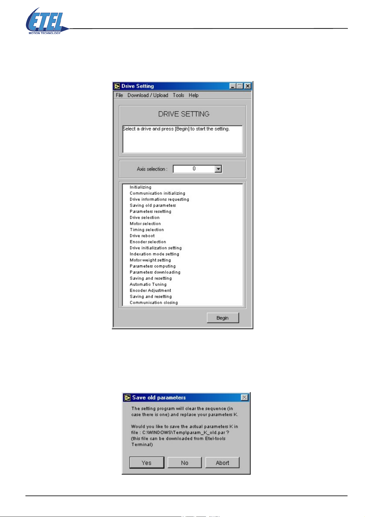
8.3 Drive Setting tool
Remark: Starting with the drive setting process is possible only if the TEB communication is established
between the DSMAX board and the controller(s) or if the EBL2 communication is established
between the PC and the controller.
Operation & Software Manual
Direct Drives & Systems 45
The Axis selection detects automatically (with EBL2 communication) the axis number; this number cannot be
changed (with TEB communication, the axis number can be selected).
• Click on the Begin button to start the drive setting process.
ETT proposes to save the 'old' parameters stored in your controller; you should click on YES.
Caution: By clicking on NO, you will loose all parameters you were previously using with the controller!
• Click on the YES button and the next window will appear.
ETEL Doc. - Operation & Software Manual # DSC2P 903 / Ver. F / 3/6/05 Chapter B: System setup & tuning
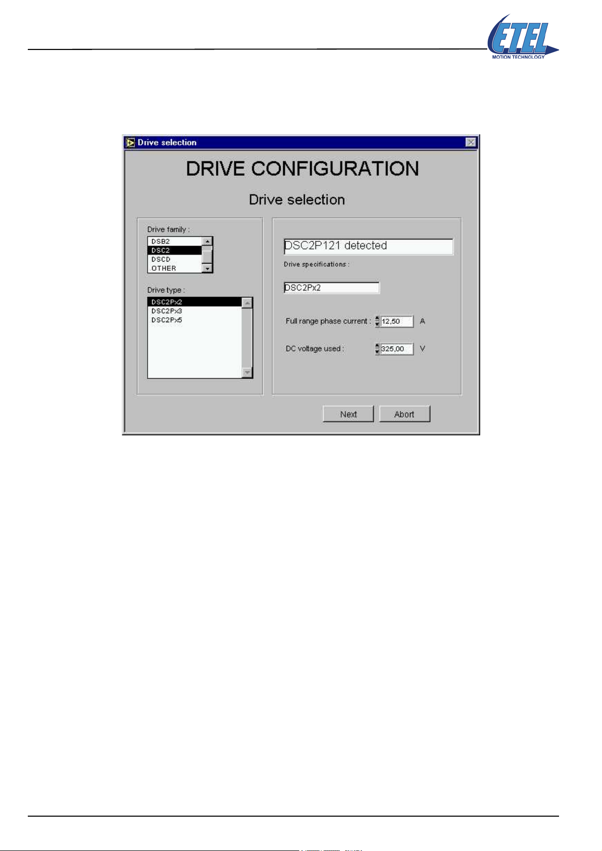
46
8.3.1 Drive selection
ETT detects automatically which controller type is connected to the DSMAX (with the TEB). The drive type
(here: DSC2Px2) and its main specifications (bus voltage = 325 VDC / Max. measurable current = 12.5 A) are
displayed:
Operation & Software Manual
Direct Drives & Systems
• Check that all data fits to your controller's characteristics.
• Click on the NEXT button and the next window will appear.
Remark: Full range phase current (measurable) Peak current
DSC2Px2 12,5 [A] 11 [A] for 2 [sec] (with 3-phase motor)
DSC2Px3 25 [A] 21 [A] for 2 [sec] (with 3-phase motor)
DSC2Px5 66,67 [A] 56 [A] for 1[sec] (with 3-phase motor)
...
DSCDPx2 12,5 [A] 11 [A] for 2 [sec] (with 3-phase motor)
...
The DC voltage used value will influence the phasing parameters (K90 to K98 and K101).
Chapter B: System setup & tuning ETEL Doc. - Operation & Software Manual # DSC2P 903 / Ver. F / 3/6/05

8.3.2 Motor selection
• The motors types manufactured by ETEL are listed in the scroll menu.
• Click on your motor family (here: ILD) and type number (here: ILD 06-030-3NA).
• The motor specification will appear in the adjacent fields on the right.
Here, the specifications are: Linear - Ironless - 3 phases
• If you are using a motor type not present in the scroll menu, click on OTHER.
Then, type the applicable values to complete the motor's specification fields.
• Select the motor max. working temperature (here: 80°C - air cooling).
Caution: This max. temperature may be reached only if the system cooling is designed accordingly!
Read the motor specifications in details to determine the cooling issues.
Operation & Software Manual
Direct Drives & Systems 47
Magnetic way period = 32.0E-3 [m]
Back EMF / Ku = 13.90 [Vs/m] or [Vs/rad]
Max peak current in a phase = 7.05 [Arms]
Max continuous current in a phase = 1.50 [Arms]
Inductance per phase = 1.81 [mH]
Resistance per phase at 20 °C = 5.96 [Ω]
• Control the motor's specifications before performing the next step.
• Click on the NEXT button and the next window will appear.
Caution: If you select a wrong motor type, the current limitation and protection parameters may not be
correctly set up in the controller. If this occurs,
the motor could burn or the wirings may be
irreversibly damaged!
ETEL Doc. - Operation & Software Manual # DSC2P 903 / Ver. F / 3/6/05 Chapter B: System setup & tuning

48
8.3.3 Encoder Selection
• The encoder types recommended by ETEL are listed in the scroll menu.
• Click on your encoder type number (here: LIDA 181 C).
• The selected encoder specification will appear in the adjacent fields on the right.
Here, the specifications are: Multi-index encoder
• If you are using an encoder type not present in the scroll menu, click on analog OTHER or TTL OTHER.
Then, type the values to complete the encoder's specification fields.
• Under Encoder processing optimization, three Parameters setting fields allow the setting of the
controller parameters K50 and K77. Default values are set by ETT. Your system will work with these
values. Ideally, you should optimize them (read this ’Operation & Software Manual’ to do it).
Click on HELP for a short explanation about these parameters.
Operation & Software Manual
Direct Drives & Systems
Encoder period = 40.00 E -6 [m]
Distance between 2 indexes = 40.00 E -3 [m]
• Under Actual system values, you can read some system data directly linked to parameters K50 and K77.
Click on the black arrow to choose which set of values you want to see:
• Check the Encoder parameters and the Actual system values before performing the next step.
Note: Parameter K77 is the encoder interpolation factor. With K77=3, the best interpolation (11 bits) is
selected. Most applications use it to have the highest position measurement resolution. However,
if the application requires a lower precision and higher speed and acceleration, you may reduce
the value of parameter K77.
• Click on the NEXT button and the next window will appear.
Chapter B: System setup & tuning ETEL Doc. - Operation & Software Manual # DSC2P 903 / Ver. F / 3/6/05

8.3.4 Initialization mode
There are two ways of initializing a motor:
The first consists in sending a constant current in the phases. In that case, the motor moves until it reaches
a 0 force position. Then, it stops on that stable balance point. Its position with respect to the magnets way
(motor's fixed part) is known because the stable balance point is always the same between two poles (as long
as the relation between the currents in the phases is constant). The longest stroke covered during the
initialization is equivalent to one magnetic period (32 mm for most ETEL's motors).
nd
The 2
phases. It determines the motor position in relation with the magnets. The advantage of this method is that the
motor does not move, but it is not as precise as the first one (20% off the optimum phase shift adjustment).
This 2
After the initialization procedure, the motor position in relation with the magnets is known with a sufficient
accuracy to work out some movements. Sometimes, the accuracy may not be sufficient. The phase shift
adjustment quality may vary from an initialization to another depending on the initial position of the motor.
These problems will be solved with the homing process (refer to the next page).
The constant current mode is selected by default, this will always work for all motors with an encoder.
way, which only works with ironcore motors, consists in sending current pulses to the motor
nd
way should be especially used with vertical linear motors, or if the system mechanical friction is high.
Operation & Software Manual
Direct Drives & Systems 49
• If you are an experienced user, you may modify this default setting (refer to the explanations above).
• Click on the NEXT button and the next window will appear.
ETEL Doc. - Operation & Software Manual # DSC2P 903 / Ver. F / 3/6/05 Chapter B: System setup & tuning

50
8.3.5 Homing mode
After the initialization, a homing (also called indexation) has to be carried out, moving the motor until it
reaches a fix reference mark called index. The motor movement can highly vary during a homing according to
the type of encoder used. Some display several indexes at regular distance from each other which enable the
user to know the motor absolute position (multi-index encoder) and others display only one (mono-index
encoder). Finally some encoders have no indexes, and homing has to be done against a fix mechanical end
stop or against a limit-switch or home switch. The homing procedure has a double aim: first, to determine
the motor absolute position, and secondly, to find a constant phase shift adjustment value for each system set
up.
• You will have to select, with the black arrows, the correct options in three scroll menus on the window:
Operation & Software Manual
Direct Drives & Systems
• Choose against which kind of reference should be performed the homing (depends on your hardware):
• Choose the movement direction for the homing and say if a limit switch is present or not:
• Four parameters (K40, 41, 42, 43) automatically defined by ETT are also displayed.
The parameters values depend on both the encoder and the homing mode you have selected.
It is possible to modify K41, 42, 43. Never modify these values unless you are an experienced user!
• Click on the NEXT button and the next window will appear.
Chapter B: System setup & tuning ETEL Doc. - Operation & Software Manual # DSC2P 903 / Ver. F / 3/6/05

8.3.6 Mass or inertia
The controller needs the mass (linear system) or the inertia (rotary system) value to correctly set up its
regulator. The whole moving mass should be included in this value (not only the motor). Take the mechanical
frictions into account to give accurate values to the controller! With a wrong value your system will not work
correctly!
• Click in the dedicated field and enter the value (here: 500.00 E -3 [kg], we have a linear system)
Operation & Software Manual
Direct Drives & Systems 51
• Click on the NEXT button, wait a few seconds until the next window appears.
8.3.7 Automatic tuning options
These options are displayed for your information only (CURRENT LOOP ADJUSTMENT, MOTOR PHASES RESEARCH,
FINE PHASE ADJUSTMENT), leave them set by default, unless you are an expert.
Note:The Current loop adjustment button is deactivated only when an ironless motor is used (low
inductance).
• Do not click on the advanced button unless you are an experienced user!.
• Put the motor in the middle of the stroke to avoid problems and click on START. The message Automatic
tuning proceeding! appears. Wait until the next window appears (in case of problem, click on Abort).
ETEL Doc. - Operation & Software Manual # DSC2P 903 / Ver. F / 3/6/05 Chapter B: System setup & tuning

52
8.3.7.1 Tuning successful
The information window above appears if the automatic tuning was successful.
• Click on OK to go back to the Automatic tuning options window and then on Finish. The following
windows appears:
Operation & Software Manual
Direct Drives & Systems
1° If you do not want to adjust the encoder's signal:
• Click on No. The parameters are saved in the controller and the setting process is finished.
2° If you want to adjust the encoder's signal:
• Click on Yes. This function is used to correct the analog encoder's amplitude and the offset errors.
• Click on Start to automatically adjust the value of parameters K70 to K73 and then click on OK.
Chapter B: System setup & tuning ETEL Doc. - Operation & Software Manual # DSC2P 903 / Ver. F / 3/6/05

8.3.7.2 Tuning not successful
If a problem has occurred during the automatic tuning, the following window appears:
Note: The AUT command is necessary to automatically calculate the regulators parameters and perform
the phases adjustment (currents), (read this ’Operation & Software Manual’ for more
information).
• Read the window and click on OK to go back to the Automatic tuning options window.
• Check if no external perturbation has disturbed the tuning, and try to click again on START
Operation & Software Manual
Direct Drives & Systems 53
• If the tuning is still not successful, an experienced user should use the Scope Window (§8.4
the settings until it is possible to successfully perform the tuning. Click on End (all options like
LOOP ADJUSTMENT, MOTOR PHASE ADJUSTMENT, FINE PHASE ADJUSTMENT
are not performed yet).
• Wait a few seconds and click on in the Drive Setting window to quit the tool.
) to modify
CURRENT
ETEL Doc. - Operation & Software Manual # DSC2P 903 / Ver. F / 3/6/05 Chapter B: System setup & tuning

54
8.4 Scope tool
Operation & Software Manual
Direct Drives & Systems
The Scope tool is used as a digital oscilloscope to set the controller's regulator parameters and to monitor their
influence on the motor's movements. It also includes a terminal (to send commands and read/write the
controller parameters). An Online Help window will appear if you click on Help in the menu bar. Point on the
items in the window to get help.
8.4.1 The icons bar
Below the menu bar, several buttons with icons or commands have their functions described below:
Open the Connection Chooser window (refer to §8.1
Reset completely the EBL2 communication between the controller(s) and the host (PC with
ETT, e.g.). It refreshes the trigger and the oscilloscope's display.
The 'emergency stop' button (similar to HLO command) stops the progression of the user's
sequence and switches off the power in the motor phases. It is used in case of emergency
(unexpected motor noise, e.g.). The Esc key on your keyboard has the same effect.
The RSD.x=255 button resets the controller (similar to RSD.x=255 command).
The SAV.x=2 button saves in the flash the registers K, X, E, R, F, as well as the axis number
(similar to SAV.x=2 command).
).
The PWR button initializes the controller and sends power into the motor phases (controller in
POWER ON mode), or switches off the power in the motor (controller in DSC2 READY mode for
example). Similar to PWR command.
The IND button starts the motor's homing process (reference marks search). Similar to IND
command.
Chapter B: System setup & tuning ETEL Doc. - Operation & Software Manual # DSC2P 903 / Ver. F / 3/6/05

The RST.x button resets the errors, (except HARDWARE OVER CURRENT and errors which
loose the position, like ENCODER POS LOST), the LED lights green and the LCD screen
displays for example DSC2 READY, as long as the cause which has produced the error is not
there any more. The motor position is kept and the instruction PWR.[axis]=1 is sufficient to reset
the motor under control (similar to RST.x command).
8.4.2 Scope menu
The Scope menu allows the user to have access to several useful tools.
Operation & Software Manual
Direct Drives & Systems 55
8.4.2.1 Upload Trace tool
This function allows the user to display the last acquisition done with the scope.
8.4.2.2 Save graph points tool
Thanks to this function, the user can save in .txt file all the points of a plot which can be used later for
calculations.
8.4.2.3 FFT analysis tool
This tool has exactly the same function as the Spectrum tool described in §2.6.5 of the ’ETEL Tools Setup
Software Manual’.
8.4.2.4 Derivative analysis
This tool enables the user to obtain the 1st, 2nd and 3rd order derivative of a plot. For example, with the plot
of a position, the user can display the corresponding speed, acceleration and jerk.
8.4.2.5 Scope Drive LCD display tool
This tool shows, on a small window, exactly the same information which appear on the display of the controller.
8.4.2.6 Scope Unit converter tool
This tool has exactly the same function as the Unit Converter tool described in §8.7
. However, it is available
only for the axis number displayed on the top left corner of the scope.
8.4.2.7 Encoder signal adjustment tool
This tool allows the user to modify the adjustment of the encoder's signals (offset and amplitude). The same
window already appeared in the controller setting (refer to §8.3.7.1
), but this tool enables the user to have
access to these parameters (K70, K71, K72, K73) without doing the whole setting again.
8.4.2.8 Encoder resolution optimization tool
Thanks to this tool, the user can set the calculation limits of the controller (parameter K50 and K77) which
determine the maximal stroke, speed and acceleration of the system plugged on the controller.
ETEL Doc. - Operation & Software Manual # DSC2P 903 / Ver. F / 3/6/05 Chapter B: System setup & tuning

56
8.4.3 Digital oscilloscope
The two-channel digital oscilloscope allows the user to view the value versus time of any M, K or X register
(M = monitoring, K = parameter, X = user variable). The register's type (ex: M), number (ex: 6), and name (ex:
theoretical position with SET/scal/map) and unit (ex:
Operation & Software Manual
Direct Drives & Systems
µ
m) are also displayed.
The Single scale display is
selected by default:
To measure the two registers displayed, it is possible to have a dual scale by unticking the box above.
In this window, the Dual scale mode is selected. The 2nd scale is on the right side of the Scope:
Chapter B: System setup & tuning ETEL Doc. - Operation & Software Manual # DSC2P 903 / Ver. F / 3/6/05

8.4.3.1 Units change
It is possible to change the units
of any register displayed on the
scope. Just click on the unit in the
dedicated field and a menu will
appear, enabling you to select a
new unit (For a position, for ex: m
/ mm / µm / nm / incr.):
8.4.3.2 Scale format change
In the scope's upper left corner,
some buttons open scroll menus
to change both the X axis and Y
axis scale's Format, Precision,
Mapping Mode, and Grid color:
Operation & Software Manual
Direct Drives & Systems 57
The scale Format buttons give you run-time control over the format of the X and Y scale markers
respectively.
By pressing the X autoscale button, ETT autoscales the X data of the graph.
By pressing the Y autoscale button, ETT autoscales the Y data of the graph.
If you want the graph to autoscale both the X axis and Y axis continuously, click on the lock switch
to lock the autoscaling mode.
8.4.3.3 Zoom and panning tools
Two buttons are used to control the operating mode for the graph:
By pressing on the panning tool, you switch to a mode in which you can scroll the visible data by
clicking and dragging sections of the graph.
By pressing on the zoom tool, you get a pop-up menu you can choose the method of zooming:
Zoom by rectangle: Zoom in on a section of the graph by dragging a selection rectangle around
that section.
Zoom by rectangle on a restricted area of the X data (the Y scale remains unchanged).
Zoom by rectangle on a restricted area of the Y data (the X scale remains unchanged).
Undo last zoom. Resets the graph to its previous setting.
Zoom in on a point. If you hold down the mouse on a specific point, the graph continuously zooms
in until you release the mouse button.
Zoom out from a point. If you hold down the mouse on a specific point, the graph continuously
zooms out until you release the mouse button.
ETEL Doc. - Operation & Software Manual # DSC2P 903 / Ver. F / 3/6/05 Chapter B: System setup & tuning

58
8.4.3.4 Cursors
Operation & Software Manual
Direct Drives & Systems
Two cursors are available; by default, their position is (0;0) and their
color is yellow for cursor A and blue for cursor B. They may be used to
measure the positions of the signals monitored on the Scope.
Cursor modes:
Click on the little locker and a menu will appear to change the mode for
each cursor:
Free, the cursor may be placed anywhere on the Scope display.
Snap to point, the cursor may be placed only on the signals traces
(equally on signal 1. or on signal 2.)
Lock to plot 1, the cursor may be placed only on the signal trace 1.
Lock to plot 2, the cursor may be placed only on the signal trace 2.
Move a cursor:
The ''cross'' button is used to move the cursors on the Scope's display:
X pos
Y pos
Another way to move a cursor is to type its coordinates directly in the position fields.
In Snap to point and in Lock to plot modes, the cursor goes automatically to the trace's
closest point (of the entered value).
X position
Y position
In the window below, the two cursors are in Lock to plot mode. Cursor A is on monitoring M11 (signal trace 1,
Lock to plot 1.), Cursor B is on monitoring M7 (signal trace 2, Lock to plot 2.):
Chapter B: System setup & tuning ETEL Doc. - Operation & Software Manual # DSC2P 903 / Ver. F / 3/6/05

Modify the cursors:
8.4.4 Scope's Trigger
This window includes also a Trigger mode button. The trigger settings enable the user to completely define
the scope's acquisition parameters and acquisition mode.
8.4.4.1 Total acquisition time
Operation & Software Manual
Direct Drives & Systems 59
To change the cursor's aspect, click on the yellow target.
Note: To suppress the cursors from the display, select Color in the scroll menu, and
click on the little ''T'' (like transparent) in the colors palette bottom left corner.
• Type in the 'Nb point' field the number of points you want to be sampled (max. 1000).
• Type in the 'Time' field the time between sampled points.
The total acquisition time displayed on the scope's X axis is:
• If we take the example of the window displayed above, we have:
8.4.4.2 Change trigger mode
• Click on the Trigger mode button: Select mode appears on the button with a pop-up menu on its right side.
It is now possible to set the trigger to four different acquisition modes: Roll, Continuous, Single or Stop
(refer to the next picture).
X = Time x 1E-3 x Nb point
0.167 x 1E-3 x 200 = 33.4 milliseconds displayed on the X axis.
•The Roll mode lets the scope run all the time.
•The Continuous and Single trigger modes have a 2nd level pop-up menu to set the acquisition's start.
• Stop will stop the acquisition on the last image displayed. If the trigger waits for a signal which is not
coming, use the Reset button to release the trigger and modify the settings.
While the button is pressed in Select mode, all the Scope functionalities are disabled. You must click again to
release the button in Trigger mode to activate the scope again.
8.4.4.3 Simple trigger
• The second level of the pop-up menu enables the acquisition start setup of the Continuous and Single
triggers.
• The first three triggers are simple:
The acquisition start can be: Immediate, at a Beginning of movement, or at an End of movement.
ETEL Doc. - Operation & Software Manual # DSC2P 903 / Ver. F / 3/6/05 Chapter B: System setup & tuning

60
Note: Reference values (theoretical) are taken into account by the trigger (not the real measured
values):
8.4.4.4 Complex trigger
• The last two triggers, Position and Parameter, are more complex.
• The second pop-up menu shows that the motor's Position can define the acquisition start.
• Type the position in the 'Value [incr]' field.
Operation & Software Manual
Direct Drives & Systems
• The acquisition can also start when a Parameter displayed on the scope reaches a defined level.
• The 1st parameter (green) is set if you click on Parameter and if you type the Value you want in the
dedicated 'Value [incr]' field (can be read with monitoring M7 [incr]).
8.4.5 Parameters
8.4.5.1 On the monitor window
Fifteen parameters that you may use to set up the controller's regulation can be displayed in the 'Parameter'
field. They will influence either the position state regulator, the current reference generator or the PI
current regulator response. These parameters are listed in two tables and DIN/DOUT status in a third one:
Chapter B: System setup & tuning ETEL Doc. - Operation & Software Manual # DSC2P 903 / Ver. F / 3/6/05
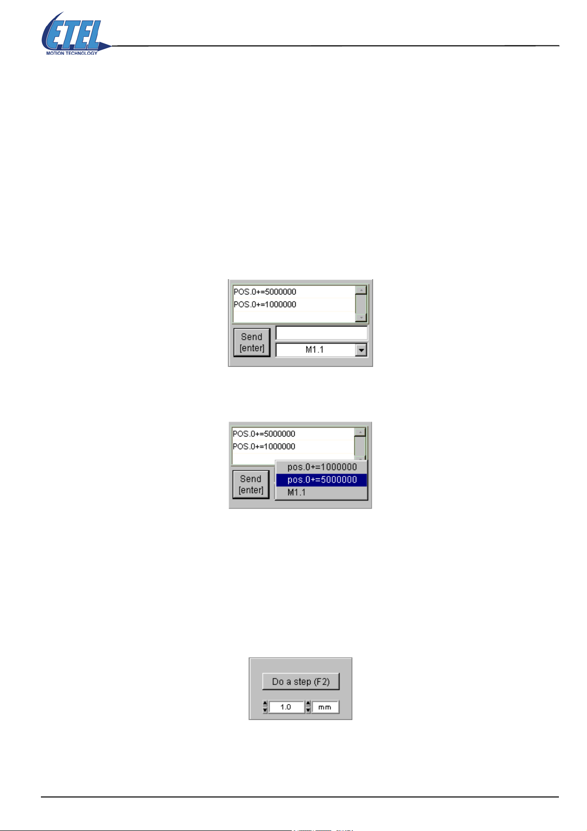
Operation & Software Manual
Direct Drives & Systems 61
Scroll the menu to choose between First set, Second set, or Din&Dout table to be displayed. It is possible to
type new parameter values in the dedicated fields.
Click on Write F5 (or press F5 on your keyboard) to accept parameter changes.
Click on Read F4 (or press F4 on your keyboard) to read the actual parameter values in the controller.
In the text field, you can work on any other parameter (here: K83). Only experts use this field; it has priority on
all other fields.
Remark:
Refer to this ’Operation & Software Manual’ if you want to understand more about these
parameters. Reading these paragraphs will also help you to understand which possible numbers
can be entered in the dedicated fields. These numbers will set the parameters to the desired
values.
8.4.6 Commands
The Scope window also includes, at the bottom right corner, a small terminal to send commands to the
controller. Firstly, type the command in the dedicated field and then press on the Send [enter] button (or type
Enter on your keyboard) to send the command to the controller.
If you want to enter one of the commands already sent, click on the black arrow and you will be able to select
one of the 11 last commands sent.
8.4.7 Step movement
In the upper part of the Scope tool window (under the icons bar), the 'Step' field is used to provide a step
movement command to the motor (back and forth step). This movement is used by experienced users to
proceed to the regulator's fine setting. Fine setting is not explained in this manual.
To perform a step movement, the controller must be in ’Power On’ mode (status on the LCD). Then, select the
movement size in the dedicated field (typically, 1.0 mm), and press on the Do a step (F2) button (or type F2 on
your keyboard) to perform the step.
ETEL Doc. - Operation & Software Manual # DSC2P 903 / Ver. F / 3/6/05 Chapter B: System setup & tuning

62
8.4.8 System identification
In the upper right corner of the Scope window, several details are displayed:
• Controller type. Here: DSC2P152.
• Firmware version installed in the controller. Here: Firmware 1.10A.
In the upper left corner of the Scope window, the following details are displayed:
• Controller axis number. Here: Axis 0.
• Daisy chain (TEB): the Axis present scroll menu shows Axis 0, Axis 1 and *(DSMAX) (Axis 31).
Axis 31 is reserved for the DSMAX; the axes number may be from 0 to 30.
Operation & Software Manual
Direct Drives & Systems
Chapter B: System setup & tuning ETEL Doc. - Operation & Software Manual # DSC2P 903 / Ver. F / 3/6/05

8.5 Terminal tool
The Terminal tool is used to communicate with the controller. It allows the user to read registers values stored
in the controller, or to send commands or registers values into the controller. All commands and the registers
syntaxes are described in this ’Operation & Software Manual’.
Operation & Software Manual
Direct Drives & Systems 63
Read registers (arrow in front of the line)
8.5.1 The icons bar
Open the Connection Chooser window (refer to §8.1).
Copy the selected text on the terminal.
Paste the last text selection on the terminal.
Unit conversion (ISO <> increments) for all values displayed on the terminal.
The 'emergency stop' button (similar to HLO command) stops the progression of the user's
sequence and switches off the power in the motor phases. It is used in case of emergency
(unexpected motor noise, e.g.). The Esc key on your keyboard has the same effect.
Send commands and registers (diamond in front of the line)
The HLT.! stops the progression of the user's sequence and stops the motor with the maximal
deceleration possible (similar to HLT.! command).
The SAV.!=0 button saves in the flash the registers K, X, E, L, S, R, F, as well as the axis number
for all axes present (similar to SAV.!=0 command).
The RST.! button reset the errors of all the axes present, (except HARDWARE OVER
CURRENT and errors which lose the position, like ENCODER POS LOST), the LED lights green
and the LCD screen displays for example DSC2P READY, as long as the cause which has
produced the error is not there any more. The motor position is kept and the instruction
PWR.[axis]=1 is sufficient to reset the motor under control (similar to RST.! command).
ETEL Doc. - Operation & Software Manual # DSC2P 903 / Ver. F / 3/6/05 Chapter B: System setup & tuning

Operation & Software Manual
64
Direct Drives & Systems
8.5.2 Read / send registers and commands to the controller
It is possible to read / send registers values and to send commands:
Read Syntax: <register_name1>[:<depth1>].<axis>[,<register_name2>[:<depth2>].<axis>], Enter
(on keyboard). The register's value appears on the same line (arrow in front of the line).
Send Syntax: <register_name>[:<depth>].<axis>[<operator>] = <p1>, Enter (on keyboard)
Syntax: <cmd_name>.<axis>[<operator>][=<p1>][,<p2>], Enter
The register's new value (or command) appears on the same line (diamond in front of the line).
After each validation (Enter on keyboard), a comment about the function appears in green on the same line.
Note: The fields put in 'square brackets' (like: [:<depth>]) are optional. (refer to §6.
explanations about the syntax described above).
8.5.3 Download sequence / registers into the controller
8.5.3.1 Download sequence
When you write a 'user sequence', you save it as a text (.txt) file on your PC (refer to §6.
commands syntax and for programming). Then, you will have to copy it into the controller, as follows:
• Click on D
•The Download Sequence window appears. Browse your PC to find the file you want. For sequences, use
*.seq files, for K parameters *.par files; *.txt files is also possible for both.
ownload/Upload then click on Download sequence from file, in the Ter m i n al menu bar.
for more
and §14. for the
• Select the file (here, the file example.txt in the example directory), and click on the 'ouvrir' (Open) button.
Chapter B: System setup & tuning ETEL Doc. - Operation & Software Manual # DSC2P 903 / Ver. F / 3/6/05

Operation & Software Manual
Direct Drives & Systems 65
• The previous window disappears and a new Download Sequence window appears.
• Select an axis and click on the D
Axis * is the DSMAX).
Remark: If a sequence is already running in the controller, the Error window below appears:
8.5.3.2 Download registers
For registers, follow the same procedure as for a sequence (refer to §8.5.3.1
Remark: The window's name will be Download Registers. The Error window will never appear.
ownload button. Wait until the sequence is completely downloaded. (The
).
ETEL Doc. - Operation & Software Manual # DSC2P 903 / Ver. F / 3/6/05 Chapter B: System setup & tuning

66
8.6 Editor tool
The Editor tool is used to communicate with the controller. It allows the user to create (write), open or modify
the sequences / registers (*.par, *.seq, or *.txt files) and to download them into the controller. It allows the user
to also upload the sequences / registers present in the controller. All commands and the registers syntax are
described in this ’Operation & Software Manual’.
Operation & Software Manual
Direct Drives & Systems
8.6.1 The icons bar
New blank editor window.
Open a text file (.txt) in the editor window.
Save the editor window contents.
Print the editor window contents.
Cut the selected text on the editor.
Copy the selected text on the editor.
Paste the last text selection on the editor.
Download the Sequence present on the editor window into the controller.
Download the Registers present on the editor window into the controller.
The 'emergency stop' button (similar to HLO command) stops the progression of the user's
sequence and switches off the power in the motor phases. It is used in case of emergency
(unexpected motor noise, e.g.). The Esc key on your keyboard has the same effect.
Chapter B: System setup & tuning ETEL Doc. - Operation & Software Manual # DSC2P 903 / Ver. F / 3/6/05

Operation & Software Manual
Direct Drives & Systems 67
8.6.2 Download (create, open, modify) sequences / registers
It is possible to directly type sequence lines or registers in the editor window. It is also possible to open
sequences and registers saved on your PC (*.par, *.seq, or *.txt files). The sequence (including or not including
registers values), or the registers may only be downloaded into the controller.
8.6.2.1 Download a sequence into the controller
• Click on D
ownload/Upload, then on Download sequence from window, in the menu bar.
•The Download Sequence window appears
• Select an axis and click on the D
ETEL Doc. - Operation & Software Manual # DSC2P 903 / Ver. F / 3/6/05 Chapter B: System setup & tuning
ownload button. Wait until the sequence is completely downloaded.

Operation & Software Manual
68
Direct Drives & Systems
Remark: If a sequence is already running in the controller, the Error window below appears:
8.6.2.2 Download registers
For registers, follow the same procedure as for a sequence (refer to previous paragraph).
Remark: The windows names will be Download Registers. The Error window will never appear.
8.6.3 Upload (create, open, modify) sequences / registers
It is also possible to upload the sequence or the registers stored in the controller. When a sequence is
uploaded, a (green) comment appears on the same line. When registers are uploaded, a (green) comment
appears on the same line for parameters K only (not for all of them).
8.6.3.1 Upload a sequence from the controller
• Click on D
ownload/Upload, then on Upload sequence to window, in the menu bar.
• It is recommended to answer Yes to the question below (to have a backup):
Chapter B: System setup & tuning ETEL Doc. - Operation & Software Manual # DSC2P 903 / Ver. F / 3/6/05

Operation & Software Manual
Direct Drives & Systems 69
•The Upload Sequence window appears.
• Select an axis and click on the U
8.6.3.2 Upload registers
For registers, follow the same procedure as for a sequence (refer to previous paragraph).
pload button. Wait until the sequence is completely uploaded.
ETEL Doc. - Operation & Software Manual # DSC2P 903 / Ver. F / 3/6/05 Chapter B: System setup & tuning

70
8.7 Unit Converter tool
The Unit Converter tool is used to set up / read position, speed and acceleration values in the controllers, in
ISO units or increments. It is also possible to read the real position, speed and acceleration values in the
controllers. These functions are available for all axes present on the Turbo-ETEL-Bus daisy chain.
Operation & Software Manual
Direct Drives & Systems
1 line
(item)
8.7.1 The icons Bar
Open the Connection Chooser window (refer to §8.1).
Add a new conversion item (new line).This
function (Add) may also be realized from the
menu:
Delete a conversion item (line).This function
(Del) may also be realized from the menu:
Remark: It is necessary to select an item (line) before deleting it.
The 'emergency stop' button (similar to HLO command) stops the progression of the user's
sequence and switches off the power in the motor phases. It is used in case of emergency
(unexpected motor noise, e.g.). The Esc key on your keyboard has the same effect.
selected line
(item)
Chapter B: System setup & tuning ETEL Doc. - Operation & Software Manual # DSC2P 903 / Ver. F / 3/6/05

8.7.2 Unit conversion
• Choose between Position, Speed or Acceleration in the
first scroll menu.
• Select also the Axis number in the second scroll menu.
• If required, you may change the ISO unit (Position, Speed or Acceleration).
Operation & Software Manual
Direct Drives & Systems 71
• With a click on the buttons below, you may upload / download Position, Speed or Acceleration, for each
line separately, and convert their values:
Upload directly from the controller (increments) the Position, Speed or Acceleration value to the
corresponding line (Inc and ISO). This is an increment > ISO value conversion.
Download directly to the controller (increments) the Position, Speed or Acceleration value (inc.
and ISO) from the corresponding line. This is an ISO > increment value conversion.
Example:
The controller is in ’Power On’ mode. The user wants to Download into the controller the following line:
Position / Axis 0 / 65536000 [Inc] / 160 / mm (click on the Download button)
This is like sending the following command from the terminal: POS.0 = 65536000 (Enter)
Note: The position value sent is always an absolute position!
ETEL Doc. - Operation & Software Manual # DSC2P 903 / Ver. F / 3/6/05 Chapter B: System setup & tuning

Operation & Software Manual
72
Direct Drives & Systems
9. Simplified regulator's principle
9.1 General diagram
)
Motor
Current loop : 1, 2 or 3 phases
Encoder
Phase 1
2
I
Phase 3
Phase 2
Set point generator: sti (refer to §4.
)
)
Regulator: cti (refer to §4.
Regulator: fti (refer to §4.
+
+
Limit
K81
Current in phase 1
Force
I
Integrator
K80
1
calculator
-
Position
calculator
: Position errorX
e
X
+
Ic
Fc
K60
Limit
++ + +
K4
K1
Integrator
e
X
+
X
a
c
K21
K20
c
V
Set point
generator
look-up table
Motor commutation
: Position reference
: Speed reference
: Force reference
: Reference of current
c
c
c
c
V
F
I
Speed
order
1
filter (x2)
estimator
K8
Motor speed v
Motor position x
: Current in phase 1
: Current in phase 2
1
F: Force supplied by the motor
2
I
I
X: Motor real position
V: Motor speed
-
-
st
K3
K2
F force supplied by the motor
-
X
c
Chapter B: System setup & tuning ETEL Doc. - Operation & Software Manual # DSC2P 903 / Ver. F / 3/6/05

Operation & Software Manual
9.2 Parameters description
The interaction between the regulator's elements will now be looked at. These explanations are more intuitive
than theoretical. They should be used to 'feel' what happens and to help the reader to set up the regulator. The
reader is supposed to have basic knowledge in automatic control. For more information, please refer to one of
the numerous works on the matter available on the market.
This regulator's description is not complete, it has been simplified for a better understanding. However, all the
main parameters listed in this chapter are sufficient to set up the controller for all typical applications.
Remark: The principles described below are generally verified; however the results will strongly depend on
the application and on the system's working conditions.
9.2.1 Current regulator
Note: Refer to §13.1.2.1 for the position regulator's K values.
A classical proportional-integral (PI) regulator is used to control the controller's current output (Refer to
§13.1.2.2
K80: Proportional gain (P).
for the current regulator's K values). The PI current regulator's parameters are:
Direct Drives & Systems 73
Speed
The main effect of parameter K80 is to make
the current response faster.
K81: Integral gain (I).
The main effect of parameter K81 is to
suppress the current permanent error.
Current
Speed
Current
Time
Ic reference current
I (K80 effect)
Time
Time
Ic reference current
K81 effect
I real current
Time
ETEL Doc. - Operation & Software Manual # DSC2P 903 / Ver. F / 3/6/05 Chapter B: System setup & tuning

74
9.2.2 Position regulator
Note: Refer to §13.1.2.1 for the position regulator's K values.
9.2.2.1 PID gains
The position feedback is controlled by a state regulator, which can be approximated by a proportional-integralderivative (PID) regulator. The position state regulator's parameters are:
K1: Proportional gain (P).
Operation & Software Manual
Direct Drives & Systems
The main effect of parameter K1 is to make the
position response faster, but it may also create
an overshoot, oscillations and a permanent
error.
Position error : Xe = Xc - X
K4: Integral gain (I).
The main effect of parameter K4 is to suppress
the position permanent error (Xe constant).
Position
Position
reference
step Xc
Xc
X (K1 effect)
perm. error
Xe constant
X (K1 low)
Time
X (K4 effect)
Time
K2: Speed feedback gain, or pseudo-derivative
gain (D). This is not a real position derivative
gain, since the input to K2 is not directly
stemmed from the position error (Xe), but
derived from the calculated speed (V).
The main effect of parameter K2 is to reduce
(suppress) the overshoot and the low-frequency
oscillations.
Position
overshoot 5% max
X (K2 effect)
Xc
Time
Chapter B: System setup & tuning ETEL Doc. - Operation & Software Manual # DSC2P 903 / Ver. F / 3/6/05
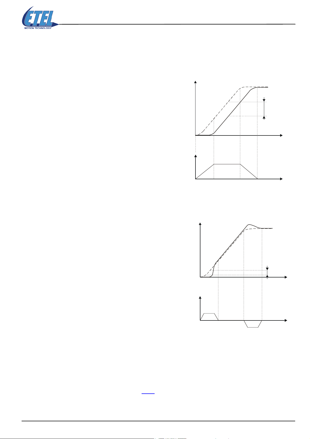
9.2.2.2 Feedforwards
)
During a movement, a permanent error may appear between the position reference and the motor's real
position. This drag can be due to mechanical frictions. It is possible to compensate it with the feedforward
parameters. These parameters will increase 'a-priori' (with anticipation, without reading the real drag) the speed
and acceleration command inputs to the state regulator. The feedforward parameters are:
Operation & Software Manual
Direct Drives & Systems 75
K20: Speed feedforward gain.
The difference between the position reference (Xc) and
the real position (X1) is similar to the speed's profile
(∆X1).
The speed feedforward will compensate the drag's
constant part. the value of parameter K20 value should
be set equal to the one of parameter K2.
K21: Acceleration feedforward gain.
Position
∆X1
Position
Mvt. reference Xc
Similar to
the speed
Mvt. reference Xc
X1 (K20 low, drag effect
Xc - X1 = ∆X1
Time
Time
X2 (K21 low, over
and undershoots)
The difference between the position reference (Xc) and
the real position (X2) is similar to the acceleration's
profile (∆X2).
The acceleration feedforward will compensate the
undershoot and overshoot remaining after the speed
feedforward compensation.
9.2.2.3 Speed filter
The speed feedback (input to K2) to the state regulator can be filtered. This speed filter is made up of 2 lowpass 1st order filters, with a -20dB/decade slope each. The state regulator's speed filter parameter is:
K8: Speed filter (no filter when K8 = 0).
Should be used when an audible high frequency perturbation occurs on the speed (f > 700 Hz).
Remark: Advanced users may refer to §13.1
Xc - X2 = ∆X2
Time
∆X2
Similar to the
acceleration
Time
for a more complete regulation loop description.
ETEL Doc. - Operation & Software Manual # DSC2P 903 / Ver. F / 3/6/05 Chapter B: System setup & tuning

Operation & Software Manual
76
Direct Drives & Systems
10. Controller regulators tuning principle
Tuning the controller's regulators gains is necessary to adapt them to the characteristics of the motor and load
that it will drive. You will use ETEL Tools for this operation, especially its Scope Tool (refer to §8.4
Caution: The following diagram describe, in a basic way, the principles to tune the controller's current and
position regulators. Of course, these procedures are general and cannot be considered as perfect
for setting all applications. Therefore, receiving a training by an ETEL support engineer is
generally necessary for the user, to be able to accurately tune a controller.
).
Chapter B: System setup & tuning ETEL Doc. - Operation & Software Manual # DSC2P 903 / Ver. F / 3/6/05

Operation & Software Manual
C
Direct Drives & Systems 77
urrent regulator's
Drive setting tool ok > Scope tool > PWR > K8=K9=K20=K21=0
basic tuning:
Do a step (T=1 STI / Nb p.=200) M30 M31
M31 bad current rise
M31 oscillations
Current saturation
(one at least) ?
YES
Current rise high
enough ?
O
Higher P gain : K80 x 1,5
NO
O
NO
High freq.
oscillations ?
(noise)
YES
Lower P gain : K80 / 2
NO
YES
Increase 'Do a step' size
M31 current rise
O
saturation
O
Do a step (T=1 STI / Nb p.=1000) M30 M31
no constant error
O
Constant error ?
YES
Higher I gain : K81 x 1,5
NO
Do a step (T=1 STI / Nb p.=200) M30 M31
High freq.
oscillations or
overcurrent ?
YES
Lower I gain : K81 / 2
NO
constant error
O
Reduce 'Do a step' size
YES
Saturation ?
(M30 >
K60)
O
NO
Current regulator's basic tuning = OK
ETEL Doc. - Operation & Software Manual # DSC2P 903 / Ver. F / 3/6/05 Chapter B: System setup & tuning
no more saturation

78
Operation & Software Manual
Direct Drives & Systems
Position regulator's
basic tuning:
Higher
Higher P gain : K1 x 1,1 to 1,5
M7 no overshoot
D gain : K2 x 1,5
pseudo
Current regulator's basic tuning = OK
THIS PAGE IS INTENTIONALLY LEFT BLANK
Do a step (T=1 / Nb p.=150) M6 M7
NO
Do a step (T=1 / Nb p.=150) M6 M7
NO
High freq.
oscillations ?
(noise)
YES
Lower
0,5% < Overshoot < 5%
D gain : K2 / 2
pseudo
?
O
Modify P gain : K1 x 0,8 to 1,2
NO
M7 oscillations on position
M7 overshoot >> 5%
Higher I gain : K4 x 1,5
constant error
(+ or -)
YES
Do a step (T=1 / Nb p.=150 to 450) M6 M7
YES
O
Constant error ?
NO
Set K20 value = K2
SAV.axis# = 2
RSD.axis# = 255
PWR
IND
POS.axis# +
Position regulator's basic tuning = OK
Chapter B: System setup & tuning ETEL Doc. - Operation & Software Manual # DSC2P 903 / Ver. F / 3/6/05
= x (< travel limit !)
High freq. noise ?
(high note)
Speed feedback filter : K8 + 1

Operation & Software Manual
Direct Drives & Systems 79
Chapter C: System functions
ETEL Doc. - Operation & Software Manual # DSC2P 903 / Ver. F / 3/6/05 Chapter C: System functions

80
11. Save the settings
The controller is set with 4Mbytes (1Mx32bits) of SDRAM memory and 2Mbytes of flash memory. The
SDRAM is a volatile memory which is erased each time the controller is switched OFF, whereas the flash is a
non-volatile memory and the data which is stored in it is not lost when the controller is switched OFF. All
calculations and operations done by the controller are made with SDRAM values.
SAV, RES and NEW commands allow the user to transfer data from the SDRAM to the flash and vice-versa.
Operation & Software Manual
Direct Drives & Systems
MEMORY
SDRAM FLASH
SAV
DATA
RES
DATA
DATA
NEW
default
values
The SAV command (SAVe) saves into the “flash” memory the controller’s data (like registers, sequences,
...), so that they are not lost when the controller is switched off and on again. Saved data is defined by the first
parameter.
The RES command (REStore) rereads the controller’s data (like registers, sequences,...), previously saved
with SAV command into the “flash” memory, and restores them into the SDRAM memory. Restored data is
defined by the first parameter.
The NEW command reloads in the SDRAM the default values of parameters K, or erases the S user sequence
stored in the SDRAM, depending on the first parameter's value.
Command format <P1> Comment
0
Saves sequence (S register), user look-up tables (L register), user variable X, parameters K,
trigger (E register), real-time interrupt (R register), float (F register) and axis number in flash
SAV.<axis> = <P1>
RES.<axis> = <P1>
NEW.<axis> = <P1>
memory
Saves sequence (S register) and user look-up tables (L register) in flash memory
1
Saves user variable X, parameters K, trigger (E register), real-time interrupt (R register), float (F
2
register) and axis number in flash memory
Restores sequence (S register), user look-up tables (L register), user variable X, parameters K,
0
trigger (E register), real-time interrupt (R register), float (F register) and axis number from flash
to ram memory if all the switches of the DIP switch are set to 1 (refer to §12.1.1
information)
1
Restores sequence (S register) and user look-up tables (L register) from flash to ram memory
2
Restores user variable X, parameters K, trigger (E register), real-time interrupt (R register), float
(F register) and axis number from flash to ram memory if all the switches of the DIP switch are
set to 1 (refer to §12.1.1
Clears sequence in ram memory and sets default K value in ram memory
0
Clears sequence in ram memory
1
Sets default K value in ram memory
2
for more information)
for more
Caution: After executing RES and NEW commands, SDRAM ordinary values are replaced by the values
read in the “flash” memory and are definitively lost. Similarly, the SAV command crushes the
values contained in ’flash’ with those contained in the SDRAM. To avoid possible problems,
SAV, RES and NEW commands should be executed if the controller is in ’Power Off’.
Chapter C: System functions ETEL Doc. - Operation & Software Manual # DSC2P 903 / Ver. F / 3/6/05

Operation & Software Manual
Direct Drives & Systems 81
Remark: When the controller is switched on, data is automatically restored, like with a RES.<axis>=0
command (so that it is not necessary to do it manually).
All parameters K depths are saved and reread when SAV, RES and NEW commands are
executed. Moreover, these commands are generally not used in a sequence but only when
sending on-line commands or with ETEL Tools.
Example:
Parameter K1 is the position loop proportional gain. The default value of this parameter is 100. The table below
shows the state of the SDRAM and the ’flash’ after realizing different actions one after the other.
Actions
Switch on the
controller
K1.1 = 5000 Parameter K1 is equal to 5000. Parameter K1 is equal to 100, value by default.
Switch off and
on the controller
K1.1 = 4000 Parameter K1 is now equal to 4000. Parameter K1 is equal to 100, value by default.
SAV.1 = 2 Parameter K1 is still equal to 4000. Parameter K1 is now equal to 4000.
NEW.1 = 2 Parameter K1 is now equal to 100, value by default. Parameter K1 is still equal to 4000.
RES.1 = 2
State of the SDRAM after acting (the controller uses
these values for all its calculations)
Parameter K1 is equal to 100, value by default Parameter K1 is equal to 100, value by default.
Parameter K1 is equal to 100, value by default. Parameter K1 is still equal to 100, value by default.
Parameter K1 is equal to 4000, value contained in the
flash.
Parameter K1 is still equal to 4000.
State of the flash after acting
ETEL Doc. - Operation & Software Manual # DSC2P 903 / Ver. F / 3/6/05 Chapter C: System functions

Operation & Software Manual
82
Direct Drives & Systems
12. Basic functions and settings (necessary to operate the
controller)
All functions defined in this chapter are necessary to operate the controller and are used for all applications.
Advanced functions in §13.
12.1 Axis number selection
The axis number of a position controller can be set either with a DIP switch or by software with the AXI
command.
12.1.1 Selection with DIP switch
Available on DSC2P DSC2V DSCDP DSCDL DSCDM
It is possible to assign or to change the axis number of the controller with a DIP switch. After each starting, the
controller takes the axis number given by the DIP switch except when all the switches are in the high position
(or low position for the DSCDM) which means set to 1 like in the pictures below. In this case the axis number
is set by the AXI command or the value previously saved in the controller or by the default value always equal
to 1 for a single axis controller (DSC2P, DSC2V) or 0 and 1 for a dual axes controller (DSCDP, DSCDM,
DSCDL). This default value is used when no AXI command has been executed or no save has been done. For
the DSCDP, DSCDL and DSCDM, as there are 16 possible values on the DIP switch for 30 axes maximum (0
to 29), the number of the first axis of a controller will be equal to the value given by the DIP switch multiplied
by 2. The second axis number of the same controller will be automatically incremented by one.
are not used in most applications. Only advanced users will have to use them.
Default position Example
The value given on the DIP switch
represents a binary value. As the
DSC2P
DSC2V
DSCDP
DSCDL
DSCDM
switch number 6 is not used, there
are 32 possibilities. The axes are
numbered from 0 to 30 because
the axis 31 is reserved for the
DSMAX.
The value (16 possibilities) given
on the DIP switch represents a
binary value.
The value (16 possibilities) given
on the DIP switch represents a
binary value.
If there are two or more controllers on the same TEB ring with the same axis number, the BAD NODE TEB
ERR error (M64=59) will appear. This error will be generated only on the duplicated node(s) and its (their) LED
’TEB OK’ will blink.
12.1.2 Selection with command AXI
The axis number given by the
following DIP switch will be equal
0
to: 2
+ 21 = 3.
The value given on this DIP switch
is equal to: 2
first axis of this controller will have
the number 6 and the second one
the number 7.
The axis number given by this DIP
switch is equal to: 2
Then, the first axis of this controller
will have the number 6 and the
second one the number 7.
0
+ 21 = 3. Then, the
0
+ 21 = 3.
Available on DSC2P DSC2V DSCDP DSCDL DSCDM
The AXI (AXIs) command is used to change an axis number. This command asks for the controller serial
number and the new axis number. The serial number is asked by security to avoid an inappropriate change of
the axis number. The AXI command MUST be used only if all the switches (of the DIP switch) are set to 1 (refer
to §12.1.1
) and in case of a dual axes controller (DSCDP, DSCDL and DSCDM), it must be used on an even
axis number with an even value.
Chapter C: System functions ETEL Doc. - Operation & Software Manual # DSC2P 903 / Ver. F / 3/6/05

Operation & Software Manual
Direct Drives & Systems 83
Command format <p1> Controller <p2> Comment
AXI.<axis> = <p1>, <p2>
controller
serial
number
DSC2P
DSC2V
DSCDP
DSCDL
DSCDM
Axis number 0-30
Changes the current axis number of a controller; <P1> is the
serial number, <P2> is the new axis number.
Axis number 0-29
Example:
The user wants to change the axis number 2 into the axis number 6:
SER.2 ;The controller gives its serial number, for example 4059.
AXI.2=4059,6 ;The axis has now the number 6 (for the DSCDP, DSCDL and DSCDM, the second axis
has now the number 7)
The new number has to be saved once for all future applications with the SAV command.
SAV.6=2 ;The new axis number has been saved (for the DSCDP, DSCDL and DSCDM, the second
axis number is calculated with regards to the first one).
Remark: The SAV command is given for the axis 6 and not for axis 2 (refer to §11.
for more information).
In case of dual axes controller (DSCDP, DSCDL and DSCDM), the SAV command must be used
only on the even axis number.
If there are two or more controllers on the same TEB ring with the same axis number, the BAD NODE TEB
ERR error (M64=59) will appear. This error will be generated only on the duplicated node(s) and its (their) LED
’TEB OK’ will blink.
12.1.3 Serial number and firmware version
Available on DSC2P DSC2V DSCDP DSCDL DSCDM
The SER command (SERial number) which is an alias of monitoring M73 is used to know the serial number of
the position controller. It can be requested by the AXI command before changing the axis number.
The VER command (VERsion) which is an alias of monitoring M72 is used to know the firmware version
contained in the controller (refer to §12.12
M Alias Name Comment
M71 - Software boot version Gives the software boot version number installed in the controller.
M72 VER.<axis> Firmware version Gives the firmware version installed in the controller.
M73 SER.<axis> Serial number Gives the serial number of the controller.
for more information).
ETEL Doc. - Operation & Software Manual # DSC2P 903 / Ver. F / 3/6/05 Chapter C: System functions

84
12.2 Motor
Available on DSC2P DSC2V DSCDP DSCDL DSCDM
The parameters described here are set only once and are normally automatically set with ETEL Tools (see §8.)
K Alias Name Controller Value Comment
K240 - Motor type -
K89 -
K54 -
K56 -
Motor phase
number and
PWM type
selection
Motor phase
number
Pairs of poles of
the motor
Motor phase and
force inversion
Operation & Software Manual
Direct Drives & Systems
01Linear motor.
Rotary motor.
Depth 0 for primary encoder and depth 1 for secondary encoder (depth 1 is ONLY
available on DSC2P and DSC2V)
One-phase motor, PWM at 24kHz (DSC2V
10
20
Two-phase motor, PWM at 24kHz (DSC2V
30
Three-phase motor, PWM at 24kHz (DSC2V
11
DSC2P
DSC2V
DSCDP
DSCDM
DSCDL
--For linear motors: K54=1
-
One-phase motor, PWM at 12kHz
21
Two-phase motor, PWM at 12kHz
31
Three-phase motor, PWM at 12kHz
14
One-phase motor, PWM at 6kHz (DSC2P
24
Two-phase motor, PWM at 6kHz (DSC2P
34
Three-phase motor, PWM at 6kHz (DSC2P
One-phase motor, PWM at 18kHz
10
Two-phase motor, PWM at 18kHz
20
Three-phase motor, PWM at 18kHz
30
1020One-phase motor
Two-phase motor
01Normal.
Inverts phases and force signs.
)
)
)
)
)
)
Motor type (parameter K240):
This parameter is only used for unit calculation by ETEL Tools program and by DLL libraries (if used). If the
values of this parameter is not correct, the motor will correctly work but the curves will not be displayed correctly
in the units given by the ETEL Tools program (meter, amp, etc.)
Remark: Monitoring M240 indicates the type of motor given either by parameter K240 or the EnDat 2.1
encoder (depending on the encoder type selection (parameter K79)).
M Name Comments
M240 Motor type Gives the type of motor connected to the position controller
Number of motor's phases and switching (parameter K89):
Tells the controller the number of motor phases. There is no difference for the user if one, two or three phase
motor is used. The meaning of each parameters is unchanged, commands are the same, etc.
For especially high inductance motors, a specific switching may be selected with parameter K89 = 11, 21 or 31.
Remark: Parameter K89 is only read when the controller is switched on. This parameter must be saved
with the SAV command when it is changed and then the controller must be switched off and on to
integrate this new data. If this new value is incorrect, the K89 BAD VALUE error (M64=41) will
appear.
Number of motor's pairs of poles (parameter K54):
Is used with rotary motors. Parameter K54 shows the number of pair of motor's magnetic poles; this parameter
is used by the motor commutation look-up table (LKT). The sinusoidal currents sent in the motor phases are
calculated by the current reference generator, with the LKT (refer also to §12.7.1.4
). With linear motors, K54=1.
Motor phase and force inversion (parameter K56):
It enables the permutation by software of the connection of the motor phases as well as the sign of the motor
force. If the phases have been inverted during the installation, any initialization will give a totally wrong
parameter K53 (refer to §12.7.1.4
). The AUT command allows the automatic calculation of the adequate value
for parameter K56.
Remark: If you manually set K56 and K52=1, it is required to perform an AUT command after, to tune K53.
Chapter C: System functions ETEL Doc. - Operation & Software Manual # DSC2P 903 / Ver. F / 3/6/05

12.3 Position encoder
Available on DSC2P DSC2V DSCDP DSCDL DSCDM
The position encoder's K parameters described below are only set once. Generally, they are automatically set
with ETEL Tools (refer to §8.
The position encoder is the device enabling the motor to measure its position. It is made up of two parts: the
head, connected to the motor, and the scale, which is fixed. Parameter K79 allows the user to select the type
of encoder(s) used on the controller.
K Name Va lue Bit # Comment
Operation & Software Manual
Direct Drives & Systems 85
).
Encoder position
K55
increments factor
Encoder reading
K68
K70
K71
K72
K73
K75
K79
way inversion
Encoder sine offset
correction
Encoder cos offset
correction
Encoder sine ampl.
correction
Encoder cos ampl.
correction
Distance between
two indexes
Encoder type
selection
--
1
2
4
- - Correction of the sine signal offset.
- - Correction of the cosine signal offset.
- - Correction of the sine signal amplitude.
- - Correction of the cosine signal amplitude.
- - Average distance between two indexes with the multi-ref. marks scales.
0
1
4
7
20
21
23
24
100
101
104
With rotary encoder: number of [dpi] / motor revolution period
With linear encoder: number of [dpi] / motor magnetic period
Analog 1 Vptp or EnDat 2.1 encoder reading way is inverted.
0
TTL encoder reading way is inverted.
1
Inverts force reference from MACRO (DSCDM
2
1 Vptp analog encoder selection (secondary = TTL for DSC2P and DSC2V)
TTL encoder selection (secondary = 1 Vptp for DSC2P and DSC2V)
EnDat 2.1 encoder selection (secondary = TTL for DSC2P and DSC2V)
TTL encoder selection (secondary = EnDat 2.1) (only on DSC2P and DSC2V)
Stepper in open loop without encoder (DSC2P
Stepper in open loop with reading of a TTL encoder (DSC2P
Stepper in open loop with reading of a 1 Vptp analog encoder (DSC2P
Stepper in open loop with reading of a EnDat 2.1 analog encoder (DSC2P
Macro mode: Analog encoder selection (1 Vptp) (Secondary = TTL for DSC2P) (DSCDM
DSCDL
)
Macro mode: TTL encoder selection (secondary = analog encoder 1 Vptp for DSC2P)
(DSCDM
Macro mode: EnDat 2.1 encoder selection (secondary = TTL encoder selection for DSC2P)
(DSCDM
and DSCDL)
and DSCDL)
and DSCDL)
and DSC2V)
and DSC2V)
and DSC2V)
and DSC2V)
and
Encoder period in [nm] (linear encoder) or number of periods per turn (rotary encoder). Depth 0
K241 Encoder period - -
for primary encoder and depth 1 for secondary encoder (depth 1 is ONLY available on
DSC2P and DSC2V)
Remark: Monitoring M13 allows the user to display the position given by the secondary encoder (for DSC2P
and DSC2V). It is also available with K79=21, 23 and 24 for DSCDP, DSCDM and DSCDL. To
interpret this value, parameters K27, K50 and K69 or K77 must be taken into account according
to the type of encoder (refer to §13.3.10
and K77 and to §13.3.10
for parameter K50).
and §13.10 for more information about parameters K69
Monitoring M5 allows the user to display the distance (dpi) covered due to the homing (used in the
case of external reference with the Macro optional board for example).
If parameter K68 is modified, the command AUT=10 must be executed to re-calculate parameters
K53 and K56.
Parameter K79 is only read when the controller is switched on and must be saved with SAV
command when it is changed and then the controller must be switched off and on to integrate this
ETEL Doc. - Operation & Software Manual # DSC2P 903 / Ver. F / 3/6/05 Chapter C: System functions

86
Operation & Software Manual
Direct Drives & Systems
new data. If this new value is incorrect, the K79 BAD VALUE error (M64=40) will appear.
For the DSCDP, if parameter K79 is modified (with K79=100, 101 and 104), the SAV command
must be executed on both axes. For the DSCDP, K79 = 4 and 104 is available only from
DSCDP3xx-xxxE. For the DSCDL, K79 = 4 is available only from DSCDL3xx-xxxC.
Parameter K55 allows the setting of the number of increments per magnetic period (linear motors)
or per turn (rotary motor); this parameter is used by the motor commutation look-up table (LKT).
Monitoring M239 indicates the encoder period given either by parameter K241 or the EnDat 2.1
encoder (depending on the encoder type selection (parameter K79)).
M Name Comments
M239 Encoder period Gives the type of motor connected to the position controller
The currents sent to the motor phases are calculated by the current reference generator with the commutation
look-up table. Here is the formula to calculate the number of increment (parameter K55):
•For rotary motor:
K77
K55 NPCod 1024 2
K55 NPCod 64 2
⋅⋅=
K69
⋅⋅=
(for analog encoder)
NPCod = Encoder periods number per turn [p/r]
(for TTL encoder)
•For linear motor:
K55
K55
Pway
----------------
PCod
Pway
----------------
PCod
1024 2
⋅⋅=
64 2
⋅⋅= (for TTL encoder)
K77
K69
Remark: Refer to §13.3.10
§13.3.10
for parameter K50.
Monitoring M241 indicates the encoder interpolation factor.
M Name Comments
M241 Encoder interpolation factor
12.3.1 Analog encoders (K79=0)
Available on DSC2P DSC2V DSCDP DSCDL DSCDM
The analog encoders (1Vptp) can determine exactly the motor position thanks to two sinusoidal signals with
a phase-shift of 90° (sine and cosine). The period of these signals varies according to the type of encoder used
(from 128 nm to 32 mm). The smaller the period is, the bigger the precision is. These signals must be calibrated
to be optimized so as to have the same amplitude and no offset. Parameters K70, K71, K72 and K73 make
such corrections. Some of the scales used with the analog encoders are multi-reference mark, and in that case
the average distance between reference marks must be given via parameter K75. Formula for linear motors:
(for analog encoder)
PCod = Encoder periods number [m]
Pway = magnetic period [m]
and §13.10 for more information about parameters K69 and K77 and to
Gives the interpolation factor of the encoder.
In the above-mentioned formulas, monitoring M241 corresponds to
1024 * 2
K77
(for an analog encoder) and 64 * 2
K69
(for a TTL encoder).
1024 Distance between 2 indexes [m]
⋅
K75
Chapter C: System functions ETEL Doc. - Operation & Software Manual # DSC2P 903 / Ver. F / 3/6/05
--------------------------------------------------------------------------------------
PCod
with PCod = encoder period [m]=

Operation & Software Manual
Direct Drives & Systems 87
The encoder resolution, which is the smallest distance measured by the encoder, is given by the following
formula:
Encoder period [m]
Analog encoder resolution [m]
------------------------------------------
=
1024 2
⋅
Interpolation factor
K77
Parameter K75 calculation, formula for rotary motors:
⋅
1024 NPCod
K75
-------------------------------
NRef
with NRef = nb. of encoder reference marks / turn=
Offset correction (K70, K71):
If parameter K70 or/and K71 is smaller than 0, a positive offset is added to the corresponding signal and a value
higher than 0 adds a negative offset. If parameter K70 or/and K71 is equal to 0, no offset correction is done.
Sensor amplitude
Signal without offset correction
K70 and K71 = 0
Position
Signal with offset correction
K70, K71 between -1024 and 1024
bigger than 0 ⇒ move down
smaller than 0 ⇒ move up
Remark: Monitorings M40 and M41 allows the user to monitor the sine and cosine signals of the analog
encoder (refer to §12.3.7
for more information).
Amplitude correction (K72, K73):
The amplitude correction only allows the decrease of the signal amplitude and never the increase of it. That is
why, the encoder head tuning is highly important because it will not be possible to correct a too weak
amplitude with the software. It is possible to decrease a signal amplitude at best by a factor 2 with the value
16384. The value 32767 does not correct any encoder signals amplitude.
Sensor amplitude
Signal without amplitude correction
A
A / 2
K72, K73 = 32767
Position
Signal with amplitude correction
for adjusting, value is included
between 32767 (·1) and 16384 (·1/2)
Remark: During offset and amplitude corrections manual research, it is advised to start first disabling
individually every signal offset, and then to correct the amplitudes in order to adjust the bigger on
the smaller.
Sensor amplitude
Signal without amplitude correction
A
A / 2
ETEL Doc. - Operation & Software Manual # DSC2P 903 / Ver. F / 3/6/05 Chapter C: System functions
K72, K73 = 32767
Position
Signal with amplitude correction
for adjusting, value is included
between 32767 (·1) and 16384 (·1/2)

Operation & Software Manual
88
12.3.2 EnDat 2.1 encoders (K79=4)
Available on DSC2P DSC2V DSCDP DSCDL DSCDM
The EnDat 2.1 encoders (analog 1Vptp) can determine the absolute position of the motor thanks to two
sinusoidal signals with a phase-shift of 90° (sine and cosine) and the information given by its two serial lines
(clock and data). The period of these signals varies according to the type of encoder used (from 128 nm to 32
mm). The smaller the period is, the bigger the precision is. These signals must be calibrated to be optimized
so as to have the same amplitude and no offset. Parameters K70, K71, K72 and K73 make such corrections.
Caution: Be careful of the length (max. 150m with distributed capacitance 90 pF/m) of the encoder cable
because the clock frequency of the EnDat 2.1 is equal to 500kHz. Refer to the encoder's
manufacturer for more information about the EnDat 2.1 encoder's cable.
Offset correction (K70, K71):
If parameter K70 or/and K71 is smaller than 0, a positive offset is added to the corresponding signal and a value
higher than 0 adds a negative offset. If parameter K70 or/and K71 is equal to 0, no offset correction is done.
Sensor amplitude
Direct Drives & Systems
Signal without offset correction
K70 and K71 = 0
Position
Signal with offset correction
K70, K71 between -1024 and 1024
bigger than 0 ⇒ move down
smaller than 0 ⇒ move up
Remark: Monitorings M40 and M41 allows the user to monitor the sine and cosine signals of the analog
encoder (refer to §12.3.7
for more information).
Amplitude correction (K72, K73):
The amplitude correction only allows the decrease of the signal amplitude and never the increase of it. That is
why, the encoder head tuning is highly important because it will not be possible to correct a too weak
amplitude with the software. It is possible to decrease a signal amplitude at best by a factor 2 with the value
16384. The value 32767 does not correct any encoder signals amplitude.
Sensor amplitude
Signal without amplitude correction
A
A / 2
K72, K73 = 32767
Position
Signal with amplitude correction
for adjusting, value is included
between 32767 (·1) and 16384 (·1/2)
Remark: During offset and amplitude corrections manual research, it is advised to start first disabling
individually every signal offset, and then to correct the amplitudes in order to adjust the bigger on
the smaller.
Parameter K75 does not exist with K79=4 contrary to K79=0.
Sensor amplitude
Signal without amplitude correction
A
A / 2
Chapter C: System functions ETEL Doc. - Operation & Software Manual # DSC2P 903 / Ver. F / 3/6/05
K72, K73 = 32767
Position
Signal with amplitude correction
for adjusting, value is included
between 32767 (·1) and 16384 (·1/2)

Operation & Software Manual
Direct Drives & Systems 89
With an EnDat 2.1 encoder, additional information can be displayed thanks to the following monitorings:
M Name Comments
M145 Encoder type Gives the type of EnDat 2.1 encoder (linear or rotary and single or multi-turn)
M146 EnDat measuring step Gives the number of measuring step per turn (for rotary encoder) or in [mm] (for linear encoder)
M147 EnDat period number Gives the number of encoder period per turn (for rotary encoder) or in [mm] (for linear encoder)
M148 EnDat pulse number Gives the number of pulse
M149 EnDat turn number Gives the number of turn
12.3.3 TTL encoders (K79=1 and K79=7)
Available on DSC2P DSC2V DSCDP DSCDL DSCDM
TTL encoders measure the motor position with two phase-shifted TTL signals. Each change of state of one of
the signals corresponds to a position increment. Parameters K70 to K73 are not used.
Signal TTL1 (UA1)
Signal TTL1 (UA1)
This formula gives the TTL encoder resolution, which is the smallest distance measured by the encoder, but
it concerns the encoder only, not the resolution obtained in the controller:
Encoder period [m]
Encoder resolution [m]
The real position reading resolution is given in the controller by parameter K55 (refer to §12.3
------------------------------------------
=
4
).
The encoder resolution, which is the smallest distance measured by the encoder, is given by the following
formula:
TTL encoder resolution [m]
Encoder period [m] 16
----------------------------------------------------
=
1024 2
⋅
⋅
K69
TTL special filter: With a TTL encoder, oscillations may happen when the motor stops and stays on a position.
When the motor moves, they disappear. They are due to the encoder weak resolution. A special speed filter,
also named “smooth filter” has been created to reduce them. It can be tuned via parameter K11.
Parameter K11 filter is taken into account only when the real speed is equal to 0. As soon as the real speed is
different from 0, parameter K11 filter is deactivated.
K Name Comment
K11 TTL speed smooth filter TTL encoder special filter on the speed (K79=1).
Remark: The difference between K79=1 and K79=7 is the type of the secondary encoder. With K79=1, the
secondary encoder, which can be used only on a DSC2P and DSC2V, is a 1 Vptp analog encoder.
With K79=7 which can be used only on a DSC2P and DSC2V, the secondary encoder is an EnDat
2.1 encoder giving an absolute position.
12.3.4 Stepper in open loop (K79=20, 21, 23 and 24)
Available on DSC2P DSC2V DSCDP DSCDL DSCDM
Refer to §12.13 for more information about the stepper in open loop.
ETEL Doc. - Operation & Software Manual # DSC2P 903 / Ver. F / 3/6/05 Chapter C: System functions

Operation & Software Manual
90
Direct Drives & Systems
12.3.5 Macro modes (K79=100, 101 and 104)
Available on DSC2P DSC2V DSCDP DSCDL DSCDM
Refer to the ’DSO-MAC User's Manual’ for more information.
12.3.6 Position factors for DLLs
Available on DSC2P DSC2V DSCDP DSCDL DSCDM
The parameters below are only used by the DLLs, to calculate the position unit with indirect encoder.
K Name Comment
K242 Position multiplication factor Used by DLLs only to calculate the position unit with indirect encoder
K243 Position division factor Used by DLLs only to calculate the position unit with indirect encoder
In ETEL Tools, all the quantities representing a position given in ISO unit can be multiplied by the Kpos-iso
factor. Kpos-iso = K242 / K243.
That way, it is possible to make the position scale bigger or smaller. The other ISO quantities (speed,
acceleration...) will be adjusted accordingly. It is really interesting for an indirect measurement of position (for
example if the user wants to measure the position on a linear movement which is caused by a rotary motor
including the encoder).
12.3.7 Encoder monitorings
Available on DSC2P DSC2V DSCDP DSCDL DSCDM
They measure the signal values given by the analog position encoder.
M Name Comment
M40 Analog encoder sine signal Encoder sine signal value
M41 Analog encoder cosine signal Encoder cosine signal value
M42 Analog encoder index signal Encoder index value (ONLY available on DSC2P and DSC2V)
M43 Analog encoder amplitude signal
The conversion formula to know the measured encoder signal value in ISO units is:
Controller For monitorings M40, M41 and M42 For monitoring M43
DSC2P
DSC2V
DSCDP
DSCDM
DSCDL
Encoder value [Vˆ]
Encoder value [Vˆ]
Analog encoder sine
Encoder value [inc]
------------------------------------------
=
=
4096 x
⋅
Encoder value [inc]
------------------------------------------
65536 x
2
+ cosine
⋅
2
M43 inc[]
M43 [Vˆ]
M43 [Vˆ]
-------------------------
=
2048 x
M43 inc[]
-------------------------
=
32768 x
⋅
⋅
The x value depends on the type of position controller:
Value Position controller
X
0.83 DSC2P and DSC2V
0.74 DSCDP, DSCDL and DSCDM
Remark: To convert ISO units ([m/s], f.e.) and ETEL units ([upi], f.e), refer to §19.
K66=4 allows the user to display on the scope the amplitude of the encoder's analog signals as
well as the position of the index.
Chapter C: System functions ETEL Doc. - Operation & Software Manual # DSC2P 903 / Ver. F / 3/6/05

Operation & Software Manual
Direct Drives & Systems 91
12.4 Precaution parameters - IMPORTANT
The parameters K described below are set only once. Generally, they are set automatically by ETEL Tools
during the Drive setting process (refer to §8.
These parameters are added up to the existing material protections (fuses, mechanical end stops, etc) and
protect the controller, the machine, its motor and its compounds. There are three types of protection
parameters: 1
overcurrent, 3
st
: those which introduce movement limits, 2nd: those which protect the motor from an
rd
: the general protection parameters which control the interactions between the motor and the
rest of the machine.
12.4.1 Movements limits
Available on DSC2P DSC2V DSCDP DSCDL DSCDM
Parameters K34 and K35 limit the linear motors movements. If the value of a position to reach programmed
with the POS command is higher than the one contained in parameter K35, the programmed position will
automatically be brought back to parameter K35. And it is the same with a value smaller than parameter K34.
In both cases the movement takes place with the limit value and the controller does not display an error
message. Parameter K36 enables or disables the activation of the protection of parameters K34 and K 35; an
error may appear (depends on the value of parameter K36) if the motor goes over the parameters K34 and K35.
Parameters K30 and K31 switch automatically off the power of the motor in case of position error or in case
of overspeed of the values contained in parameters K30 and K31. In that case the controller switches in error
mode, lights a red error LED and displays a message to identify the error.
).
Valid for K Name Va lue Bit # Comment Units
All
motors
K30
tracking error limit
Motor real speed
K31
K36
Minimum software
K34
Maximum software
K35
Search limit stroke
K145
Motor position
limit.
Motor position
limitation mode
position limit.
position limit
mode selection
(SLS mode)
-
-
1
2
4
-
-
0
1
2
3
When the tracking error is > K30, the controller generates the TRACKING
ERROR error (M64=23)
When the speed is > K31, the controller generates an OVER SPEED
error (M64=24)
0
Use of parameters K34 and K35 as limit on the target the motor can
reach. These limits are tested on every sti only if a homing has been
previously done. Used with K61=1
Use of parameters K34 and K35 as limit on the actual position of the
1
motor. If the motor reaches these limits, it generates an OUT OF
STROKE error (M64=65). These limits are tested on every sti only if a
homing has been previously done. Used for all values of parameter K61
Use of parameters K34 and K35 as limit on the target to generate an REF
2
OUT OFSTROKE error (M64=66) when the movement starts. These
limits are tested only if a homing has been previously done. Used with
K61=1. This error is generated when one of the following command is
executed: POS=, POS+=, POS-=, STE=, STE+=, STE-=, STA= and STI=
Depending on the values of K36 and K61 parameters, the motor cannot
go lower than parameter K34
Depending on the values of K36 and K61 parameters, the motor cannot
go higher than parameter K35
SLS on mechanical end stop, positive movement.
SLS on mechanical end stop, negative movement.
SLS on limit switch, with positive movement
SLS on limit switch, with negative movement
[dpi]
[rdpi]
[dsi]
[rdsi]
-
[upi]
[rupi]
[upi]
[rupi]
-
Rotary
motors
only
K27
Maximum
position value
--
Defines the maximum position range limit (K27). Depth 0 for primary
encoder and depth 1 for secondary encoder (refer also to §12.10.4.2
)
[upi]
[rupi]
Remark: If K145 = 0 or 1, parameters K41, K42, K43, K44 and K47 are taken into account (refer to §12.9
for more information).
If K145 = 2 or 3, parameters K41, K42, K47 and K58 are taken into account (refer to §12.9
for
more information).
ETEL Doc. - Operation & Software Manual # DSC2P 903 / Ver. F / 3/6/05 Chapter C: System functions

92
Operation & Software Manual
Direct Drives & Systems
SLS (Search Limit Stroke) command is:
Command format Comments
SLS.<axis>
Remark: A homing must be done (with IND command) before sending the SLS command.
The SLS command is available only when K61 = 1.
If K36=2, an error appear
Note: With K36 = 1 the target of a POS / STA / STI movement is limited by parameters K34 and K35
without generating an error.
12.4.2 Current limits
Available on DSC2P DSC2V DSCDP DSCDL DSCDM
An overcurrent in the motor phases can destroy it. Parameters K83, K84 and K85 help to avoid it. Parameter
K60 will limit the force/torque reference (theoretical) at the position regulator's output. Thus, the current in the
motor should also be limited. However, the real force/torque in the motor may oscillate and go over parameter
K60.
Searches the limit stroke according to parameter K145. Limit position is returned in monitorings M36 and
M37 (given in [upi]). K47 is taken into account by SLS command but not in M36 and M37.
MOTOR
If K36=2, an error appear
K35K34
K Name Comment Units
K83
K84 I2t rms current limit The integration starts when the motor current is > K84 -
K85 I2t time limit If the integral value is > K85, the I2T ERROR error (M64=4) appears -
K60 Force/torque limit Max. force/torque reference at the position regulator output (will limit the current in the motor)
M Name Comment Units
M67
M82
Motor
overcurrent limit
I2t integration
limit test
Controller
maximum current
If the current in the phases is > K83, the OVER CURRENT error appears (M64=2 or 3) [ci]
[foi]
[toi]
When monitoring M67 is greater than parameter K85, the controller generates an I2T ERROR
error (M64=4)
Maximum current [A] = M82/100. Should never be reached! This theoretically maximum value
is used for calculations only
[A]*100
-
Parameter K83 protects the motor from an instantaneous overcurrent. If the motor current gets higher than
the value of parameter K83, the controller changes to error mode. OVER CURRENT1 (M64=2) or OVER
CURRENT2 (M64=3) message is displayed.
Reaching the current in monitoring M82 is not permitted; this value is a theoretical measurable value, for
calculations only! (refer to §20.2
).
Parameters K84 and K85 protect the motor from a too high current during a too long time, whose energy
could raise the temperature high enough to burn the motor. This i
2
t (energy) limit is given by parameter K85.
When the instantaneous current value increases over the value of parameter K84, an integrator is activated.
As long as the current stays over the value of parameter K84, it is integrated, but when it passes under it the
integrator empties progressively. If the integral value is higher than parameter K85, the controller displays an
I2T ERROR error (M64=4).
Chapter C: System functions ETEL Doc. - Operation & Software Manual # DSC2P 903 / Ver. F / 3/6/05

Operation & Software Manual
Direct Drives & Systems 93
Current I
K83
K84
t
M67 (integral)
It
2
K85
Remark: It may happen that, during a periodic movement (machine cycle), parameter K84 may temporarily
be overcome, and the integrator may not entirely be empty at the end of the cycle. In that case,
after several cycles, an I2T ERROR error (M64=4) is displayed. The cycle is then called an
unstable cycle.
error
t
Caution: All software protections described above cannot protect at 100% a motor against overheating;
calculation of the energy balance in the whole system is required to avoid overheating.
Thus, ETEL cannot be hold as responsible in case of system failure due to motor overheating.
The next example explains how to calculate parameters K83, K84, K85. Some information concerning the
system configuration has to be known.
Motor:
I
peak: Motor peak current [A] (this is also the max current of the application).
m
I
continuous: Motor continuous current [A].
m
t: Maximum time at I
I
current: Ultimate motor current value, for a motor OVER CURRENT error [A] (= Im peak [A] + 20%)
over
Controller:
I
controller: Maximum current of controller [A] = M82 / 100
max
Parameter K83 motor over current limit:
K83
Parameter K84 i2t rms current level:
K84
peak before an i2t error [s].
m
I
current 32768⋅
over
----------------------------------------------
=
Imcontinous
---------------------------
=
M82 100⁄
M82 100⁄
100⋅
2
0.8192⋅
Caution: If a 2-phase linear motor performs a back and forth movement with very short strokes, only
one phase will be used. Thus, thermal load will be concentrated on the half of the motor
surface. Take parameter K84, (value obtained with formula above) and divide it by 2: K84
short_stroke = K84 / 2.
Parameter K85 i
ETEL Doc. - Operation & Software Manual # DSC2P 903 / Ver. F / 3/6/05 Chapter C: System functions
2
t integration limit (energy):
K85 9830 t
⋅⋅=
Im peak
------------------------
M82 100⁄
2
Imcontinuous
–
------------------------------------
M82 100⁄
100⋅
2
100⋅

94
Operation & Software Manual
Direct Drives & Systems
Example:
Motor: I
Controller: DSC2P1
peak = 7.96 A
m
I
continuous = 3.196 A
m
t= 5 s
I
current = Im peak + ~20% = ~1.2 · Im peak = 9.55 A
over
21xx I
955, 32768⋅
-------------------------------
3.196
-------------
12 5,
K84
K83
=
K85 9830 5
12.4.3 Safety signals on DIN and DOUT
Available on DSC2P DSC2V DSCDP DSCDL DSCDM
When a motor is integrated in a complex machine and an error is detected in the controller, it is important to
send a message about it to the rest of the machine so that the other elements can adequately react. This is
possible with the digital outputs (the DSO-HIO optional board's outputs are not concerned). Parameter K37
allows the user to select the digital outputs to be used. When an error occurs, the outputs selected by
parameter K37 change from the logical value ’1’ to ’0’. For example, DOUT1 can be connected to a relay which
short-circuits the motor phases in case of error, making a magnetic brake. The outputs that have to be
activated in case of error are chosen via the binary value of parameter K37.
controller = (M82 / 100) = 12,5 A
max
12 5,
2
100⋅
7.96
⋅⋅=
------------
12 5,
25000==
0.8192 536=⋅
2
100⋅
3.196
-------------
12 5,
2
100⋅
167000000=–
The number of digital outputs is different from a position controller to another. Here is a table giving the number
of digital outputs present on each position controller (refer to the corresponding ’Hardware Manual’ for more
information):
DSC2P / DSC2V DOUT # 4321
DSCDP / DSCDL DOUT # --21
DSCDM DOUT # -321
Caution: On the DSCDM, the digital inputs and outputs are on the same pin. The pin must be selected in
order to have an input or an output. It is NOT possible to have both on the same pin. To use
a pin as a digital input, the bit corresponding to this input MUST be equal to 0 in parameter K171.
Example:
To activate DOUT3 of the DSC2P or DSC2V, parameter K37 has to be set to 4, because it corresponds to
0000000000000100 binary. Several outputs can be activated simultaneously, for example, DOUT2 and
DOUT1 are selected with value 3 (0000000000000011 bin).
K37
3 0 0 0 0 0 0 0 0 0 0 0 0 0 0011
4 0 0 0 0 0 0 0 0 0 0 0 0 0 0100
Bits# 3 to 15
not used
Bit# 3
DOUT4
Bit# 2
DOUT3
Bit# 1
DOUT2
Bit# 0
DOUT1
Decimal Binary
On the contrary, parameter K33 switches the controller in error mode by adding the number 0 and switches off
the power if DIN1 digital input is not set to 1. The error displayed on the LCD screen shows POWER OFF/ON
Chapter C: System functions ETEL Doc. - Operation & Software Manual # DSC2P 903 / Ver. F / 3/6/05

Operation & Software Manual
Direct Drives & Systems 95
(M64=26). An external error can also be detected by the controller, with this system. It is important to notice
that only DIN1 input can be used to perform this function. If the PWR instruction is given while parameter K33
contains the value 0 and that DIN1 is not set to 1, the controller also switches in POWER OFF/ON error mode
(M64=26).
K Name Va lu e Comment
Select cleared
K37
DOUT if error
K33
Power on/off
with DIN1
Remark: Refer to §13.4
Mask of the digital output (DOUT), that must be cleared when the controller is in error. When the
controller is not in error any more, the digital outputs have DOUT value.
0
Enabled signal is necessary to power up the controller on DIN1. In this case this input must be at 1
when a PWR.<axis>=1 command is executed. If this input is cleared, the controller generates a
POWER OFF/ON error (M64=26).
Enabled signal not used (DIN1 is not taken into account). PWR.<axis>=1 command powers up the
125
motor.
for more information about the digital inputs and outputs.
12.4.4 Motor temperature, TEB time-out and analog encoder error check
Available on DSC2P DSC2V DSCDP DSCDL DSCDM
• When the bit# 0 of parameter K141 is equal to 1, the motor temperature is checked by the DSC2P or/and
DSC2V, and the MOTOR OVERTEMP error (M64=29) will appear in case of overheating. (ONLY available
on DSC2P and DSC2V).
• When the bit# 1 of parameter K141 is equal to 1, the TIMEOUT TEB ERR error (M64=56) will appear if a
communication problem is detected by the controller on the TEB.
• When the bit# 2 of parameter K141 is equal to 1, the ENCODER AMPLITUD error (M64=20) or
ENCODER POS LOST (M64=21) will appear if a problem is detected on the analog encoder as secondary
encoder (ONLY available on DSC2P and DSC2V).
• When the bits# 3, 4, 5 and 6 (of parameter K141) associated to its corresponding digital input, is equal to 0,
the controller generates a MOTOR OVERTEMP error (M64=29) (DSC2P
K Name Val ue Bit # Comment
1
0
Enables test of motor overtemperature protection (PTC), connected on TSD signal (Only
available on DSC2P and DSC2V)
Enables time-out TEB error test
1
Enables the control of the error on the analog encoder if secondary encoder (Only available
2
on DSC2P and DSC2V)
Enables test of motor's overtemperature protection connected to DIN1 (DSC2P
3
Enables test of motor's overtemperature protection connected to DIN2 (DSC2P
4
DSCDM
)
Enables test of motor's overtemperature protection connected to DIN9 (DSC2P
5
Enables test of motor's overtemperature protection connected to DIN10 (DSC2P
6
K141
overtemperature
Motor
protection
2
4
8
16
32
64
and DSC2V).
and DSC2V)
, DSC2V and
and DSC2V)
and DSC2V)
Caution: On the DSCDM, the digital inputs and outputs are on the same pin. The pin must be selected in
order to have an input or an output. It is NOT possible to have both on the same pin. To use
a pin as a digital input, the bit corresponding to this input MUST be equal to 0 in parameter K171
(otherwise the hardware of the controller and the one of the user can be damaged).
Remark: For a dual axes controller (DSCDP, DSCDL and DSCDM), if parameter K141 is modified the SAV
command must be executed on both axes.
DIN1, 2, 9 and 10 are standard inputs then be careful when choosing the type of temperature
sensor (digital only). Refer to the corresponding 'Hardware Manual' for more information about
the inputs.
ETEL Doc. - Operation & Software Manual # DSC2P 903 / Ver. F / 3/6/05 Chapter C: System functions

96
12.4.5 Vpower DC bus voltage
Available on DSC2P DSC2V DSCDP DSCDL DSCDM
Parameters K146, K147, K148 and K149 are used to give the errors and warnings limits values of the input
voltage.
K Name Value Comment Units
0
Disables test on Vpower
> 0
Warning activated: Vpower level is tested.
If Vpower[V]*100<K146, the controller generates a W UNDER VOLTAGE warning M66=10)
0
Disables test on Vpower
> 0
Error activated: Vpower level is tested.
If Vpower[V]*100<K147 the controller generates an UNDER VOLTAGE error (M64=9)
0
Disables test on Vpower
> 0
Warning activated: Vpower level is tested.
If Vpower[V]*100> K148, the controller generates a W OVER VOLTAGE warning (M66=4)
0
Disables test on Vpower
> 0
Error activated: Vpower level is tested.
If Vpower[V]*100 > K149, the controller generates an OVER VOLTAGE error (M64=6)
K146
K147
K148
K149
Vpower
undervoltage
warning
Vpower
undervoltage
error
Vpower
overvoltage
warning
Vpower
overvoltage
error
Operation & Software Manual
Direct Drives & Systems
[V]*100
[V]*100
[V]*100
[V]*100
Remark: Each axis of the DSCDL has its own parameters K146, K147, K148 and K149 whose values is
used for +Vpower and -Vpower.
• For the DSC2P / DSC2V, monitoring M91 is used to indicate the DC input voltage level (Vpower).
M Name Comment Units
M91 Vpower measurement Gives the DC input voltage level (Vpower): Vpower[V] = M91 / 100 [V]*100
• For the DSCDL, monitorings M91 and M92 are used to indicate the positive and negative DC input voltage
level (respectively +Vpower and -Vpower).
M Name Comment Units
M91 +Vpower measurement Gives the positive DC input voltage level (+Vpower): +Vpower[V] = M91 / 100 [V]*100
M92 -Vpower measurement Gives the negative DC input voltage level (-Vpower): -Vpower[V] = M92 / 100 [V]*100
12.4.6 Fuse check
Available on DSC2P DSC2V DSCDP DSCDL DSCDM
Parameter K140 allows the user to enable or disable the check of the fuse protecting the supply of the encoders
K Name Valu e Comment
K140 Mask for fuse control
0
1
Enables the test of the fuse
Disables the test of the fuse
Remark: On the DSC2P, this parameter can be used only from the DSC2Pxxx-xxxC version.
It is also possible to monitor the state of this fuse with monitoring M140.
M Name Value Comment
M140 Fuse status
0
1
Fuse is not broken
Fuse is broken
Remark: If the check of the fuse is enabled and if the fuse is broken, the ENCODER FUSE KO error
(M64=35) will appear.
Chapter C: System functions ETEL Doc. - Operation & Software Manual # DSC2P 903 / Ver. F / 3/6/05

Operation & Software Manual
Direct Drives & Systems 97
12.5 Errors and warnings handling
Available on DSC2P DSC2V DSCDP DSCDL DSCDM
Errors may be detected by the controller if a precaution limit is exceeded, or if a hardware failure occurs, e.g.
Each error corresponds to a value of monitoring M64, readable by the user. It shows which error has taken
place in order to handle it adequately. Some limits will give a warning before the error appears, to allow the
user to solve the problem. Each warning corresponds to a value of monitoring M66, readable by the user.
Messages also appear on the DSC2P and DSC2V LCD display (16 characters).
When an error is identified, the Errors reference list (§19.
the problem.
M Name Comment
M64 Error code Number of the occurred error
M66 Warning code Number of the occurred warning
12.5.1 Troubleshooting
Note: Troubleshooting is permitted only for ETEL technicians and agreed distributors!
Points to check in the Errors reference list are indicated as follows:
Enc = x Error may be due to the encoder and its cable.
Mot = x Error may be due to the motor and its cable.
Hrd = x Error may be due to the hardware of the controller.
Hrd Error may be due to the a part of the hardware of the controller (F7= fuse7, DSP = Sharc,...)
K value(s) Error may be due to a bad setting of the listed parameter(s).
PS = x Error may be due to the power supply (DSO-PWS).
TEB = x Error may be due to the Turbo-ETEL-Bus communication protocol.
EBL2 = x Error may be due to the ETEL-Bus-Lite 2 communication protocol.
Other Error may be due to the reason described in the cell.
SW Res = x It is possible to reset the error by software (RST command).
HW Res = x It is recommended or compulsory to reset the error by hardware (RSD command or switch
off/on)
Brk = OFF/ON OFF or ON means that this error activates or deactivates the dynamic braking (when used).
) is used to enable the user to identify the cause of
Example:
Displayed
M64
message
OVER
2
CURRENT1
OVER
3
CURRENT2
4 I2T ERROR
OVER
5
TEMPERAT
ETEL Doc. - Operation & Software Manual # DSC2P 903 / Ver. F / 3/6/05 Chapter C: System functions
The measured current in
phase 1 is greater than K83
The measured current in
phase 2 is greater than K83
This occurs when M67
becomes greater than K85.
This is a power protection (of
the motor and/or the controller)
The temperature of the
controller is greater than 70°C.
This is measured by a
thermostat mounted on the
heat sink.
Comment Enc Mot Hrd K PS TEB EBL2 Other
K60, K80,
xx
xx
K81, K82,
K83, K98
K60, K80,
K81, K82,
K83, K98
K1, K2,
K4, K52,
K53, K56,
K84, K85
Friction /
duty cycle
Heat
evacuation
SW
resHWres
xOFF
xOFF
xOFF
xON
Brk

Operation & Software Manual
98
12.5.2 Reset errors: RST and RSD
Available on DSC2P DSC2V DSCDP DSCDL DSCDM
RST command (ReSeT) resets most of the errors that can happen in the position controller.
RSD command (ReSet Drive) resets the hardware board.
Remark: RSD command consists in switching off and on the controller, so if an autorun sequence exists
(label n°79), it will start again after executing RSD command.
In a sequence, these commands are generally placed in the labels n°80 which is the label in which
the program execution goes on in case of error.
Command RST, used with a single axis, starts automatically the instruction CPE described
underneath.
Command format Comment
RST.<axis> Resets the error flags of the controller (bit# 10 of SD1)
RSD.<axis> = 255 Hardware resets of the controllers.
Direct Drives & Systems
Example:
If during a movement, the position error x
power is cut off, the LED lights red and the LCD display shows TRACKING ERROR error (M64=23). This error
can be reset with one or other of the RST or RSD commands:
RST.1 The error is reset, the LED lights green and the LCD screen displays for example DSC2P
READY, as long as the cause which has produced the error is not there any more. The motor
position is kept and the instruction PWR.1=1 is sufficient to reset the motor under control.
RSD.1=255 The board is reset and the motor position is erased. A new initialization has to be redone in
order to find again the absolute motor position.
12.5.3 Clear errors: CPE
Available on DSC2P DSC2V DSCDP DSCDL DSCDM
CPE command (Clear Pending Error) resets to 0 the ’pending’ error bit when required.
Command format Comment
CPE.<axis> Pending error bit set to 1 in case of error
becomes too big. The controller switches then to error mode. The
e
When an error happens, the execution of a sequence goes on automatically on label n°80 (if it exists) and an
internal bit of the controller called ’pending’ error, is set to 1 (bit# 0 of SD2 ’Status Drive’, alias of monitoring
M61). As long as the ’pending’ error bit is set to 1, it is forbidden for the controller to jump to label 80, so that it
can execute the line following the label 80, and tries to correct the error. Without this ’pending’ bit and as long
as the error is there, the sequence would jump endlessly on label 80 and gets stuck there without going on with
the execution of the rest of the sequence.
In the code contained in label 80, the error is generally handled with monitoring M64 and the RST command.
This command, apart from resetting the error, resets the ’pending’ error bit to 0. This way, when the following
error takes place, it enables again the controller to jump to label 80.
Chapter C: System functions ETEL Doc. - Operation & Software Manual # DSC2P 903 / Ver. F / 3/6/05

Operation & Software Manual
Direct Drives & Systems 99
12.5.4 Errors management with the µ-master
Available on DSC2P DSC2V DSCDP DSCDL DSCDM
When an axis enters in error mode, the µ-master (DSC2P and DSC2V only) is immediately informed about it
thanks to the information running on the frame of the TEB. In this case, the µ-master sends an error in all the
other axes by sending the !ERR.! command in emergency record via the TEB. All the axes which were not in
error will go in EXTERNAL ERROR error (M64=116). The !ERR.! command is sent only once by the µ-master.
Only the execution of the RST command allows the µ-master to send again the !ERR.! command (when an
axis is in error).
All this is possible as long as the TEB works properly. If there are problems on the TEB (error,...), it is possible
to send the TIMEOUT TEB ERR error (M64=56) in all the axis if the bit# 1 of parameter K141 is set to 1. This
error can be activated or deactivated with a parameter because if the user wants to work with the controller in
single mode (without TEB connection), he does not want it to be in error. In all the modes using the TEB, it
is highly recommended to enable this error by setting the bit# 1 of parameter K141 to 1.
During the initialization of the TEB, if the µ-master tests that the TEB is not at least once in ’Ready’ mode (which
means no error) in the first 5 seconds, it will enters in SELFTEST TEB ERR error (M64=54).
12.5.5 Dynamic braking
Available on DSC2P DSC2V DSCDP DSCDL DSCDM
The dynamic braking is used to quickly stop the motor when an error arises and allows the user to protect the
mechanical system during an emergency braking. It is based on the short-circuit principle at the terminals of
the motor.
Caution: This function cannot be considered as a safety system because there is no mechanical
protection (relay), the function is managed by a software and a voltage is present at the
motor's terminal! (continuous alternating switching of the transistors (GND - Vpower)).
Due to this voltage, it is strictly forbidden to touch the system (controller, cable and
motor) as long as the mains is not switched off.
Bit 4 of parameter K32 is used to enable or disable the braking mode (refer also to §12.9
about parameter K32). Once enabled (K32¦ = ∅x10), 2 types of error having an opposite effect on the braking,
can arise. These two types of error (refer to §19.
'brake off' cancelling the braking. The deactivation takes always priority over the activation.
• If a ‘brake off’ error type arises, the braking will not be reactivated by a ‘brake on’ error type. It can be done
only after a ‘PWR.<axis>=1’ or RSD.<axis>=255 command.
• If a ‘brake on’ error type arises, followed by a ‘brake off’ one, this second error type will not be displayed
but the braking will be deactivated.
for more information
for the list) are: 'brake on' activating the braking mode and
• The ‘RST’ command does not have any effect on the braking mode. The latter can be reset only after a
PWR.<axis>=1 or RSD.<axis>=255 or by resetting and setting again bit# 4 of parameter K32. If the
braking is activated, a vertical motor will not suddenly fall against the mechanical end stop after the ‘RST’
command.
• During the braking, there is a protection against the overcurrent in order to protect the controller and the
system. The braking is deactivated (power bridge opened) when the current in one phase is bigger than
75% of the software overcurrent error (parameter K83). The braking is reactivated when the current in all
phases is again smaller than this limit.
• During the braking, there is also a protection against the I2t in order to protect the controller and the
system. The braking is deactivated when monitoring M67 (I2t value) is bigger than 75% of I2t error
(parameter K85). The braking is reactivated when monitoring M67 is again smaller than this limit.
ETEL Doc. - Operation & Software Manual # DSC2P 903 / Ver. F / 3/6/05 Chapter C: System functions

Operation & Software Manual
100
Direct Drives & Systems
12.6 Basic reference mode (K61=1)
Available on DSC2P DSC2V DSCDP DSCDL DSCDM
Parameter K61 allows the user to set the reference mode. The standard reference mode (also called normal
or basic reference mode) is set when K61 = 1. This mode is the most frequently used mode (described up to
now in this manual) To use it, the user needs to set:
• a type of movement defined by parameter K202 (or the MMD command which is an alias of parameter
K202). Refer to §13.3.1.3
for more information.
• the references of the movement which are (refer to §12.10.3
for more information):
• a final position to reach defined by parameter K210 (or the POS command which is an alias of
parameter K210)
• the maximum speed defined by parameter K211 (or the SPD command which is an alias of
parameter K211)
• the maximum acceleration defined by parameter K212 (or the ACC command which is an alias of
parameter K212)
• the jerk time defined by parameter K213 (or the JRT command which is an alias of parameter
K213) when a S-curve movement is selected
All these references are calculated by the set point generator generating the movement trajectory. Refer to
§13.1.1
Remark: Refer to §13.2
for more information about the complete diagram of the regulation loop.
for more information about the other values of parameter K61.
Chapter C: System functions ETEL Doc. - Operation & Software Manual # DSC2P 903 / Ver. F / 3/6/05
 Loading...