

Page 1

GSM/GPRS Modem
User's Manual
Page 2

CONTENTS
Chapter 1 GPRS/GSM Modem Overview
1. 1 Product Description
1. 2 Product Features
Chapter 2 Hardware Installation
2. 1 Standard Shipment Contents
2. 2 Connecters
2.3 LEDs Indicators
2.4 Hardware Installation
Chapter 3 AT Commands for the Modem
1
1
1
3
3
3
4
4
6
Chapter 4 Troubleshooting
4.1 No connection with the modem through the serial link
4.2 Receiving ERROR Message
4.3 Receiving No carrier Message
“ ”
“ ”
AppendixA Standard Definition of RS-232 Interface 10
Appendix B Interpretation of extended error code
10
7
7
8
9
GSM/GPRS Modem User's Manual
Page 3
Chapter 1 GSM/GPRS Modem Overview
Chapter 1 GS0/G35S Modem Overview
1. 1 Product Description
GSM/GPRS Modem is a industrial external MODEM which can transmit
data based on GPRS (General Packet Radio Service). Self-contained EGSM/GSM-GPRS 850/1900 dual-band. Give your full 2.5G GSM/GPRS Voice
and data application. It also provides the function of USSD data terminal. Housed
in a rugge d metallic casing, the modem is build to withstand the toughest
environments applications such as power plant control and outer door data
gathering.
1. 2 Product Features
Model
TD-8011
TD-8012
TD-8013
TD-8014
Channel
Circuit Channel
CLASS 2
CLASS 10
CLASS 10
1. 3 Product Features
1.31 Product standard
Dual Band GSM/GPRS (GSM850/1900MHz)
Compatible to ETSI GSM Phase 2+
1.32 Voice function
Telephony and Emergency calls
Full rate, enhanced full rate and half rate (FR/EFR/HR)
Echo canceling and noise eliminating
Speakerphone
Dual tone multi frequency function (DTMF)
Rate
14.4K
28.8K
48K
48K
IP Function
None
None
None
Available
1.33 Data Function
GSM Data/Fax features:
Data circuit asynchronous, transparent and non transparent up to 14,400 bits/s
Automatic fax group 3 (Class 1 and Class 2)
GPRS Data/Faxfeatures ( )It Cannot Be Applied in TD-8012
Coding schemes: CS1 to CS4
PBCCH support
GSM/GPRS Modem User's Manual
1
Page 4
Chapter 1 GSM/GPRS Modem Overview
1.34 Message Service
Point to point (MT/MO)
EMS
1.35 GSM Supplementary Service
Call Forwarding, Call Barring
Multiparty
Call Waiting and Call Hold
USSD
1.36 Other Operation
Software upgrade through XMODEM
SIM, Network and Service Provider Locks
Real Time Clock
Alarm Management
VCS2 Character set Management
1.37 Antenna
Frequency range: Dual Band GSM 850/PCS 1900 Mhz
Impedance: 50 Ohms
Gain (antenna + cable): 0 dBi
VSWR (antenna + cable): -10 dB
1.38 Power Supply
12V DC 1A
1.39 Environmental and mechanism
Operating temperature range: -20 to +55
Storage temperature range: -25 to +70
Overall dimensions: 96 54 25mm
× ×
Weight: 105g
℃ ℃
℃ ℃
2
GSM/GPRS Modem User's Manual
Page 5
Chapter 2 Hardware Installation
2. 1 Standard Shipment Contents
Contents Description
Chapter 2 Hardware Installation
GSM/GPRS MODEM
User's Manual
Power Adaptor
Standard RS-232 Cable
Antenna
One set
GSM/GPRS
12V DC Power Adaptor
DB-9F to DB-9M Cable
Dual Band Antenna
MODEM User's Manual
If any item above are not received, please contact us or our sales agent.
2. 2 Connecters
External Antenna Connector
Standard RS-232 Serial Interface (DB9-F to DB9-F)
Power Plug
Sliding SIM Holder
GSM/GPRS Modem User's Manual
3
Page 6

Chapter 2 Hardware Installation
2.3 LEDs Indicators
LED Status
On
OFF
LED light activity Modem status
LED ON Permanent
LED Flashing Slowly
LED Flashing Rapidly
LED OFF
Modem is switched on
Not registered on the networ k
Idle mode C onnected to the network
Transmission mod e
Modem is switched off.
2.4 Hardware Installation
2.41 MODEM QuickStart
To set up the modem, do the following:
Press SIM card holder ejector (yellow button) with a sharp object (the tip of a
pen for example).
Insert the SIM card in the holder.
Verify the SIM card fits in the holder properly.
Connect the antenna to the SMA connector.
Connect both sides of the serial and control cable
Connect the power adaptor to the power supply, and plug into the Modem.
Now the modem is ready to work. Refer to Chapter 3 for some AT commands
to configure the modem.
2.42 Checking the communication with themodem
Connect the RS232 link between the DTE (port COM) and the modem(DCE).
Configure the RS232 port of the DTE as follows:
Bits per second: 115200 bps or 9600 bps
Data bits: 8
Parity: None None
Stop bits: 1
Flow control: Hardware Flow control control.
Using a communication software such as Hyperterminal program, enter the
AT command. The response of the modem must be OK displayed in the
Hyperterminal window.
If the communication cannot be established with the modem, do the following:
Check the RS232 connection between the DTE and the modem (DCE),
Check the configuration of the port COM used on the DTE.
4
GSM/GPRS Modem User's Manual
Page 7
2.43 Verifying the received signal strength
To verify the received signal strength, do the following:
Using a communication software such as HyperTerminal program, enter the
AT command AT+CSQ. Value appears for the received signal strength.
Verify the result with the values given in the table below:
Chapter 2 Hardware Installation
Value of Received Signal Strength
(AT+CSQ Response)
0-10
11-31
Greater than 99
Interpretation of the
Received Signal Strength
Insufficient
Suffic ient
Insufficient
2.44 Verifying the network registration of the modem
Make sure a valid SIM card has been previously inserted in the SIM card
holder of the modem.
Using a communication software such as HyperTerminal program, enter the
following AT command: AT+CREG? . Value appears as a response.
Verify the result with the values given in the table below:
Value Network registration
0,1
0,5
Yes (r egistered roaming)
Yes
If the modem is not registered, perform the following procedure:
Check the connection between the modem and the antenna.
Verify the signal strength to determine the strength of the received signal
(refer to paragraph 2.43)
GSM/GPRS Modem User's Manual
5
Page 8

Chapter 3 AT Commands for the Modem
Chapter 3 AT Commands forthe Modem
The table below reminds the main AT commands required for getting started the
modem:
Description
Description
MODEM S
ynchronization
Checking
Receiving an
incoming call
Initiate a call
AT Commands Modem's Response Comment
OK
AT+CP IN=1234
AT+CREG?
ATA OK
ATD<phone
number>;
(Don't fo rget
the ; at the
《 》
end for voice
call)
《 》
+CME ERROR:16
+CME ERROR:3
CREG=<mode> 1
CREG=<mode> 2,,
CREG=<mode>, 0
OK
CME ERROR 11:
CME ERROR 3:
PIN Code accepted.
Incorrect PIN Code
(with +CMEE = 1 mode).
PIN already entered
(with +CMEE = 1 mode).
Modem synchronised on
the network.
Synchronization lost,
resynchronization attempt.
Modem not synchronized
on the network, no
synchronization attempt .
Answer the call.
Communication established.
PIN code no t entered
(with +CMEE = 1 mode).
AOC credit exceeded or a
commu nication is already
stablished.
ATD112; (Don't
Initiate an
emergency call
Communicatio n
loss
Hang up ATH OK
Store the
parameters in
EEPROM
forget the ;
at the end for
voice call)
《 》
AT&W
《 》
OK
NO CARRIER
6
Communication
established.
The configuration
settings are stored in
EEPROM.
GSM/GPRS Modem User's Manual
Page 9

Chapter 4 Troubleshooting
Chapter 4 Troubleshooting
This section of the document describes possible problems encountered when using
the Modem and their solutions.
4.1 No connection with the modem through the serial link
If the modem does not answer through the serial link, refer to the table below for
possible causes and solutions.
If the modem
returns…
Nothing
Then ask Action
Is the modem powered
correctly?
Does the serial cable
follow correctly pin
assignment shown in
paragraph 1.2.1.3.
Is the communication
program properly
configured?
Provide a power supply in the
range of 5 V (5.5V for GPRS
Class 10) to 32 V.
Connect the cable by following
pin assignment given in
paragraph 1.2.1.3.
Ensure the setting of the
communication program is fit
to setting of modem.
Modem factory setting is:
Data bits = 8
Parity = none
Stop bits = 1
Baud = 115200 bps or 9600bps
Flow control = Hardware
Is there another program
interfering with the
communication program
(i.e. Conflict on
communication port
access)
GSM/GPRS Modem User's Manual
Close the application
(e.g. mouse or printer driver).
7
Page 10

Chapter 4 Troubleshooting
4.2 Receiving "ERROR" Message
If the modem return a message of ERROR upon an attempted transmission of data,
or voice signals, then refer to the table below for possible causes and solutions.
If the modem
returns…
ERROR
Then ask Action
Is the modem registered
on the network?
Is the modem receiving an
incoming call or is it already
in communication?
Is the selected bearer type
is supported by the called
party?
Is the selected bearer type is
supported by the network?
Refer to paragraph 4.4 to
verify that th e modem is
registered on the network.
End any incoming by using
ATH command.
Enter AT+CMEE to view the
extended error code.
Note: Refer to Table 1 5.
Ensure that the selected bearer
type is supported by the called
party.Ensure that the semicolon
(;) is entered immediately after
the phone number in the AT
command. e.g. ATD######;
Is the received signal strong
enough?
Is the antenna properly
connected?
Refer to paragraph 3.4 to verify the
strengt h of th e received signal.
Refer to paragraph 2.3 for antenna
requirements
8
GSM/GPRS Modem User's Manual
Page 11

Chapter 4 Troubleshooting
4.3 Receiving "No carrier" Message
If the modem return a message of No carrier upon an attempted transmission of
data, or voice signals, then refer to the table below for possible causes and
solutions.
If the modem
returns…
No c arrier
No c arrier (when
trying to i ssue a
voice communication )
No c arrier (when
trying to i ssue a
data communication)
Then ask Action
Is the received s ignal
strong enough?
Is the antenna pr operly
connected?
Is the semicolon (;)
entered immediately after
the phone number in the
AT command?
Is SIM card configured for
data / fax calls?
Is the selected bearer type
supported by the called party?
Is the selected bearer type
supported by the network?
Refer to paragraph 4.3 to
verify the strength of t he
received signal.
Refer to paragraph
3.4 fo r antenna
requirements.
Ensure that the semicolon (;) is
entered immediately after the
phone number in the AT
command.
e.g. ATD######;
Configure the SIM card
for data / fa x calls (Ask
your network provider if
necessary).
GSM/GPRS Modem User's Manual
9
Page 12
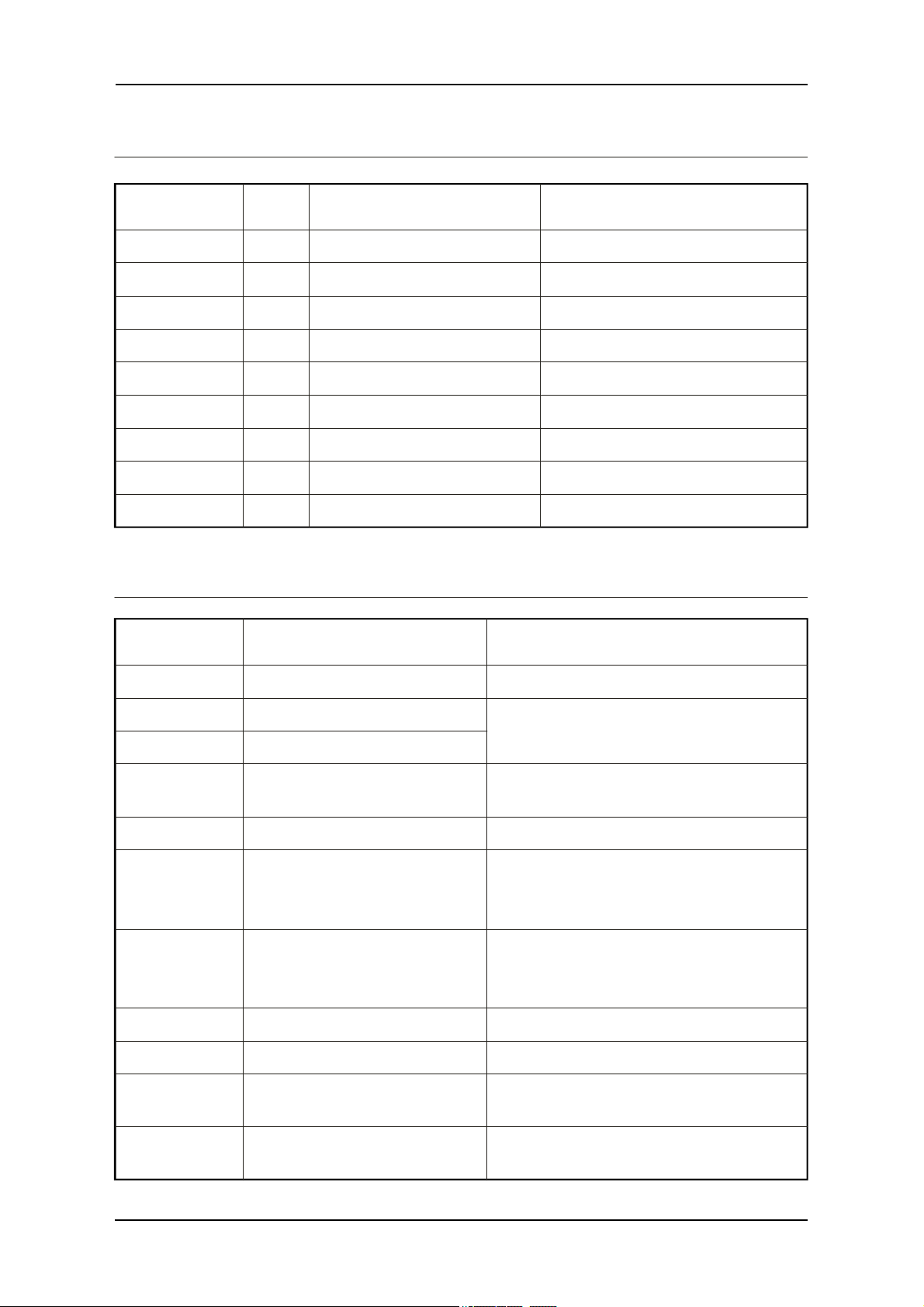
Appendix A: Standard Definition of RS-232 Interface
AppendixA: Standard Definition of RS-232 Interface
RS-232 PIN I/O RS-232 Standard Description
1
2
3
4
5
6
7
8
9
O
O
I
I
-
O
O
I
O
CD
RXD
T XD
DTR
GND
DSR
CTS
RTS
RI
D ata Carrie r Det ec t
Receiv e ser ial da ta
Tra nsm it serial dat a
D ata Termi nal Re ady
G roun d
D ata Set Re ady
Clear To Se nd
Reque st To Send
Ring I ndicator
Appendix B: Interpretation of extended error code
Error Code Diagnostic
0
P hone failu re
Call you r technical suppo rt.
Hint
3
4
10
11
12
13
16
17
18
26
O perati on not all owed
O perati on not su pported
S IM not ins erted
S IM PIN required
S IM PUK r equir ed
S IM Failur e
Incorrect pas sword
SIM PIN2 re quired
SIM PUK2 r equired
Dial st ring too long
If SIM card is inserted, check the SIM
card if it is cle an an d properly inserted.
Enter PI N cod e.
Enter PUK c ode.
Note: Call yournetwork provider if
you don'tknowthis code.
Check validi ty of your SIM card.
If SIM card damaged, call your
networ k provider.
Check the code you en tered .
E nter PIN2 code.
Enter PUK2 code (call your network
provider if you don't know this code).
Check your phone number (max 20
digits).
10
GSM/GPRS Modem User's Manual
Page 13
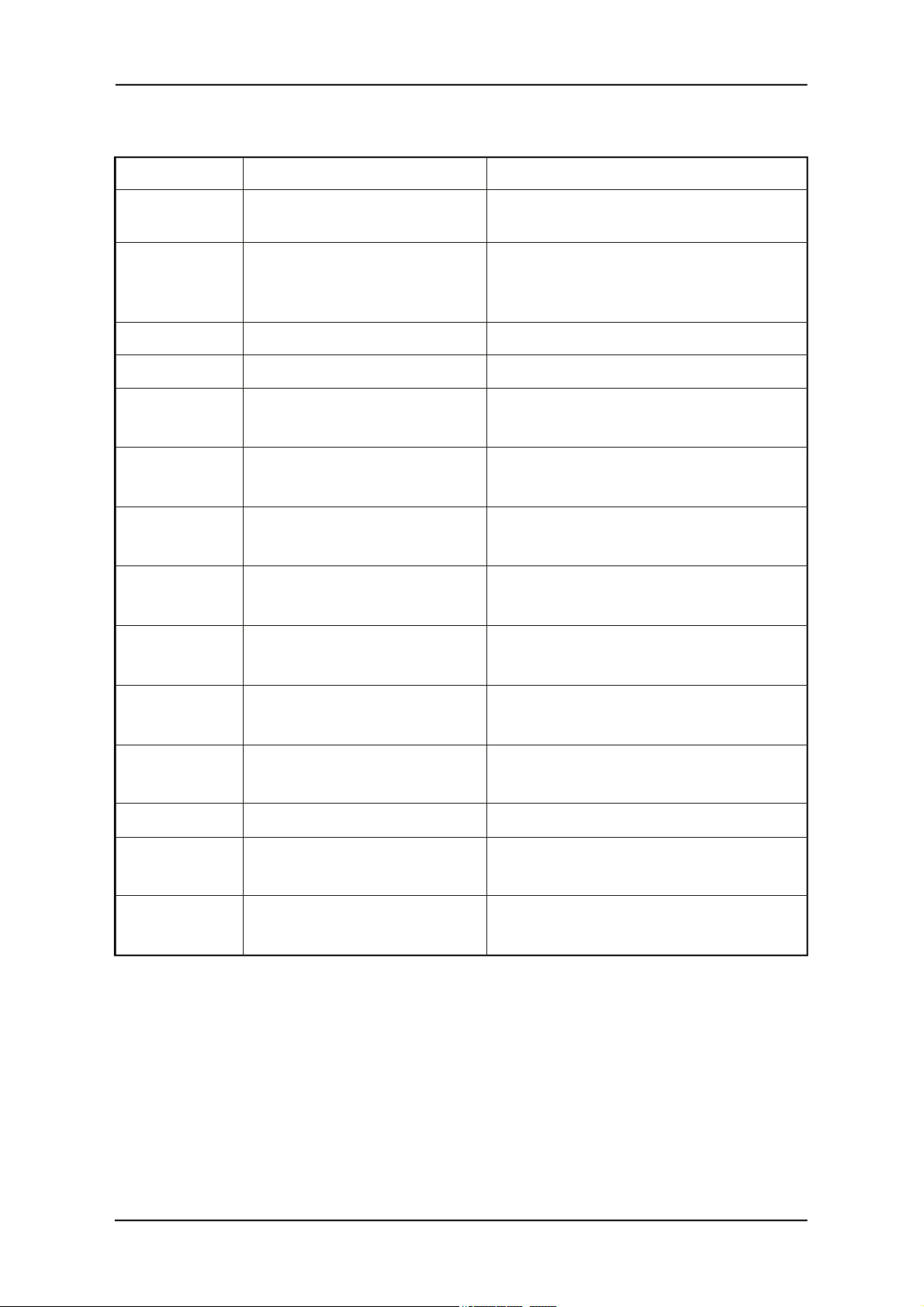
Appendix B: Interpretation of extended error code
30
32
40
103
106
107
111
112
113
No network service No action.
Network not a llowed
Emergency calls only
Network
personalization PIN required
(Network lock)
Illegal MS (#3)
Illegal ME (#6)
GPRS services not
allowed (#7)
PLMN area not
allowed (#11)
Location area not
allowed (#12)
Roaming not allowed in this
location area (#13)
No action.
Enter Network lock code (call yo ur
network provider if you don't know
this code).
No action.
No action.
Contact your network provider to
subscribe to the GPRS services.
132
133
134
148
149
150
Service option not
supported (#32)
Requested service option not
subscribed (#33)
Service option temporarily
out of order (#34)
Unspecified GPRS error
PDP authentication failure
Invalid mobile class
Call your network provider to subscribe
to the requested service option.
Call your network provider to know the
right authentication parameters.
Change the class of the mobile to a valid
one.
GSM/GPRS Modem User's Manual
11
Page 14

FCC STATEMENT
This device complies with Part 1 5 of the FCC Rules. Operation is subject to the
condition that this device does not cause harmful interference.
This equipment has been tested and found to comply with the limits for a C lass B digital device,
pursuant to part 15 of the FCC Rules. These limits are designed to provi de reasonable protection
against harmful interference in a residential installation. T his equipment generaters, uses and can
radiate radio frequency e nergy and, if not installed and used in accordance with the instr uctions,
may cause h armful in terference t o ra dio com munications. H owever, th ere is n o guarantee that
interference will not occur in a particular i nstallation. If this e quipment do es cause h armful
interference to radio or television reception, which can be determined by turning the equipment off
and on, the user is enc ouraged to try to c orrect the interference by one or m ore of the fol lowing
measures:
—Reorient or relocate the receiving antenna.
—Increase the separation between the equipment and receiver.
—Connect the e quipment into an outlet on a circuit d ifferent from that t o w hich the rece iver i s
connected.
—Consult the dealer or an experienced radio/ TV technician for help.
FCC Radiation Exposure Statement:
This equipment complies with FC C ra diation ex posure l imits set forth for an u ncontrolled
environment. In ord er to a void the p ossibility of ex ceeding t he F CC rad io fre quency ex posure
limits, Hu man pr oximity to t he an tenna sha ll not be less t han 20cm (8 inc hes) during n ormal
operation
 Loading...