

ETEKCITY MSR-R500 User Manual

User Manual
Digital Multimeter
model no.: MSR-R500
Questions or Concerns? support@etekcity.com
visit etekcity.com for more products

- 1 - - 2 -
Safe and Proper Usage Safety Operating Procedures
Thank you for purchasing the Etekcity® MSR-R500 Digital
Multimeter. Measure DC and AC voltage, current, diode and
audible continuity, and resistance with the convenience of
one single tool with built-in overload protection.
WARNING: TO AVOID THE RISK OF ELECTRIC SHOCK
OR THE DAMAGE OF THE MULTIMETER OR OTHER
EQUIPMENT, DO NOT CONNECT TO ANY INPUT
TERMINALS OF THE MULTIMETER THAT MAY
EXCEED 500V.
Read all the instructions provided in this manual. Failure to
comply with the instructions in the manual and/or use of
the device in ways other than the ones mentioned in the
manual may result in serious injury, fire, and/or electrical
shock. The person responsible for this equipment must
ensure that all users understand the directions and adhere
to them.
This meter complies with standard IEC61010: in pollution
degree 2, overvoltage category (CAT I 600V, CAT II 300V)
and double insulation.
CAT I: Signal level, special equipment or parts of
equipment, telecommunications, electronic, etc.
CAT II: Local level, appliance, PORTABLE EQUIPMENT etc.,
with smaller transient overvoltages than CAT III.
Be sure to read, understand and comply with all the
instructions in this manual
Make sure the test leads are in a safe state. Keep
equipment out of humidity or moist environments.
DO NOT use the meter if it is damaged or the case (or part
of the case) is removed. Look for cracks or missing plastic.
Check the insulation around the connectors before use.
DO NOT use the equipment in wet environments.
Remove the test probes from the item of measurement
before changing the settings or measurement functions on
the multimeter.
DO NOT apply the multimeter to voltages that may exceed
500V.
DO NOT measure voltages when the meter is set to
measure resistance (Ω).
Always use the fuses of the correct type as specified
within the instructions to avoid any injury, electrical shock,
or risk of fire.
DO NOT operate the meter around explosive gas, vapor,
or dust.
When operating the test probes, keep your fingers behind
the finger guards.
When making electrical connections, connect the common
test lead (black) before connecting the live test lead (red).
When disconnecting, disconnect the live test lead (red)
before disconnecting the common test lead (black).
Always remove the test leads before replacing the
battery within the multimeter or opening the battery
compartment.
Inspect the condition of the test leads and the multimeter
for any damage before operating the meter. Repair or
replace any damage before use.
Verify the meter’s operation by measuring a known
voltage before and after using the meter.
- 3 - - 4 -
DO NOT change the settings on the rotary switch while
the test leads are measuring a source of power.
Use great care when making measurements if the voltages
are greater than 25VAC rms or 35VDC. These voltages are
considered to be a shock hazard.
DO NOT operate the meter with the battery cover
removed or the case open.
DO NOT remove the cover or open the case of the meter
without first removing it from the main power source.
DO NOT allow children to operate this device.
USE a 9V DC battery when replacing the battery within the
device.
Make sure to insert the battery under the correct polarity
indicated in the device.
DO NOT use leaking batteries.
DO NOT dispose old batteries in fire.
Expired or damaged batteries can cause cauterization
on contact with skin. Always therefore, use suitable hand
gloves for protection in such cases.
Disconnect circuit power and discharge all high voltage
capacitors before testing resistance, continuity, diodes, or
capacitance.
Before measuring current, check the meter’s fuses and
turn off power to the circuit before connecting the meter
to the circuit.
In the case the device is going to be unused for an
extended period of time, remove the battery before
storage.
AC or DC Low Battery
AC Current Diode
DC Current Fuse
Earth Ground Continuity Test
Double Insulated Warning
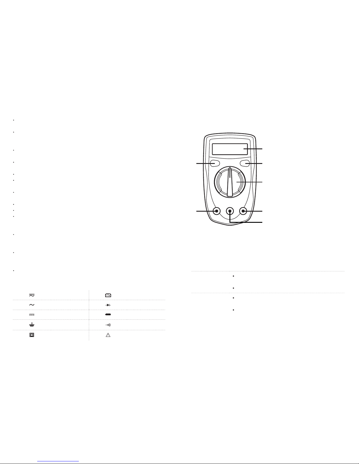
1. LCD Display
2. HOLD Button
3. Backlight Button
4. Rotary Switch
5. COM Terminal
6. 10A Terminal
7. Other Terminals
1
3
4
5
7
2
6
Figure 1
Meter Diagram
Button Functions
Button Operation
HOLD Press once to lock measurement results
(An ‘H’ symbol will appear on the display)
Press once more to unlock results
BACKLIGHT Press once to turn on the display
backlight
Press once more to turn off backlight
 Loading...