


ETEC PH-42FB31, PH-50FB31 Schematic
PDP TELEVISION
PH-42/50FB31

CONTENTS
Safety precautions………………………………………………………………………..…
Criterion for identifying the defects on screen……………………………………………
Alignment instructions …………………………….…….………………………………….
Method of software upgrading……………….…….……………………………………….
Working principle analysis of the unit……………………………….………….………….
Block diagram…………………………………..………………………………….…………
IC block diagram………………………………………………………………………..……
Wiring diagram ……………………………………………………………………………….
Troubleshooting guide ………………………………………………………………..……..
Schematic diagram…………………………………………………………………………..
APPENDIX: Exploded View
1
2
5
8
15
17
18
26
27
38

Note: This maintenance manual is intended only for the reference of the maintenance people.
Please pay attention to the following points before carrying out the maintenance work.
Safety Precautions
Please read the “Points for attention for the Maintenance & Repair of PDP” and “Criterion for
Identifying the Defects on Screen” as below, before inspecting and adjusting the TV set.
1. “Points for attention for the Maintenance & Repair of PDP”
To avoid possible danger, damage or jeopardy to health and to prevent PDP screen from new
damage, the maintenance people must read the following carefully. If they ignore the following
warnings, there will be deathful risks:
1.1 Screens vary from one model to another and therefore not interchangeable. Be sure to use the
same type of screen in the replacement.
1.2 The operation voltage is approximately 350V for PDP module (including screen, driving circuit,
logic circuit and power module). If you want to conduct maintenance work on PDP module when the
set is in normal operation or just after the power is off, you must take proper measures to avoid
electric shock and never have direct contact or touch with the circuitry of the working module or
metal parts. That’s because within a short time relatively high voltage still remains on the capacitor
of the driving part even after the power is off. Make sure to begin relevant maintenance operation at
least one minute after the power is off.
1.3 Don’t apply on the module any power supply that is higher than the specification. If the power
supply used deviates from the value given in the specification, there might be a possibility of leading
to fire or damage to the module.
1.4 Never have operation or mounting work under unsuitable environment such as areas in the
vicinity of water – bathroom, laundry, water chute of kitchen – sources of fire, heat-radiation parts or
direct exposure to sunlight. Otherwise there will be kickbacks.
1.5 In case foreign substances such as water, liquid, metal slices or others fall into the module
carelessly power must be cut off immediately. Keep the module as it is and do not move anything on
the module. Otherwise it might be possible to contact the high voltage or cause shock short circuit
so that it may lead to fire or electric shock.
1.6 If there is smoke, abnormal smell or sound from the module, please cut the power off
immediately. Likewise in case the screen doesn’t work when the power is on or during the operation,
please also cut off the power at once. No more operation in this case.
1.7 Do not remove or plug its connection wire when the module is in operation or right after the
power is off. That’s because there remains a relatively high voltage on the capacitor of the driving
circuit. If there is a need to remove or plug in the connection wire, please wait at least one minute
after the power is off.
1.8 Considering the module has a glass faceplate, please avoid extrusion by external force lest it
should cause glass breakage that may get people injured. Two people are needed in cooperation to
move this module lest contingency takes place.
1.9 The complete TV set is designed on the basis of full consideration of thermal dissipation by
convection, with the round hole on the top for heat emission. To avoid overheat, please do not have
any covering on the hole during normal operation and never put it in the place where the space is
narrow and in bad ventilation.
1.10 There is quite a number of circuits in PDP that are integrated ones. Please be on guard against
1
static electricity. During maintenance operation be sure to cover yourself with anti-static bag and
before operation make sure to have it sufficiently grounded.
1.11 There are a big number of connection wires distributed around the screen. Please take care
not to touch or scuff them during maintenance or removing the screen, because once they are
damaged the screen will fail to work and it’s not possible to repair it.
If the connection wires, connectors or components fixed by the thermotropic glue need to disengage
when service, please soak the thermotropic glue into the alcohol and then pull them out in case of
damage.
1.12 Connector for the circuit board of the screen part is relatively fine and delicate. Please take
care in the replacement operation lest it should get damaged.
1.13 Special care must be taken during transportation and handling because strenuous vibration
could lead to screen glass breakage or damage on the driving circuitry. Be sure to use a strong
outer case to pack it up before transportation or handling.
1.14 Please put it for storage in an environment in which the conditions are under control so as to
prevent the temperature and humidity from exceeding the scope stipulated in the specification. For
prolonged storage please cover it with anti-moisture bag and have them piled and stored in one
place. The environmental conditions are tabulated as below:
Temperature Scope for operation 0~50centigrade
Scope for storage -15~60centigrade
Humidity Scope for operation 20%~80%
Scope for storage 20%~80%
1.15 If a fixed picture is displayed for a long time, difference in its brightness and color may occur
compared with movable pictures. But it doesn’t show any problem and the reason is that there is
reduced density of fluorescent powder in the former. On the other hand, even if changes take place
in the picture, it can keep its brightness for a period of time (several minutes). It’s a feature inherent
with plasma and it’s not abnormal. However please try as much as possible to avoid showing a still
picture of high brightness for a long time during operation.
1.16 As a digitalized display devise, this module is provided with error diffusion technology and the
gray scale and false enhancement of contour can be displayed by reusing of sub-field. As compared
with cathode ray tube, it can be found in the moving picture that at the brim of the face of a person
there are some wrong colors.
1.17 During the display of graph (indicating the gradual change in brightness horizontally or
vertically) resulting from gray scale test it can be found that the brightness for the two adjacent
levels is uneven. This is caused by the reuse of sub-field, the display of load rectification and the
electrolysis.
1.18 The screen front plate is of glass. Please make sure that the screen has been put in place
during erection. If it is not in place before the erection begins it may lead to screen crack or
breakage.
1.19 Make sure the screw used in the mounting of the screen is of the original specs lest it should
cause damage to the screen due to mismatch. Special care should be taken not to use too long or
too big screw.
1.20 Care must be taken to guard against dust during assembling or dismantling, especially to avoid
dirt from falling in between the screen and the glass lest it should harm the receiving and viewing
2
effect.
1.21 There is piece of insulator stuck on the rear chassis corresponding to the power supply board.
It is used to isolate the cool part from the hot part. Please take care to keep it intact lest it should
become a potential safety trouble.
1.22 In addition to plasma screen, the glass is a part of high value. It has such functions as
anti-radiation, adjustment of color temperature etc. Please handle it carefully.
2. “Criterion for Identifying the Defects on Screen”
The PDP produced by our Company at present uses the following criterion for identifying the
defective points:
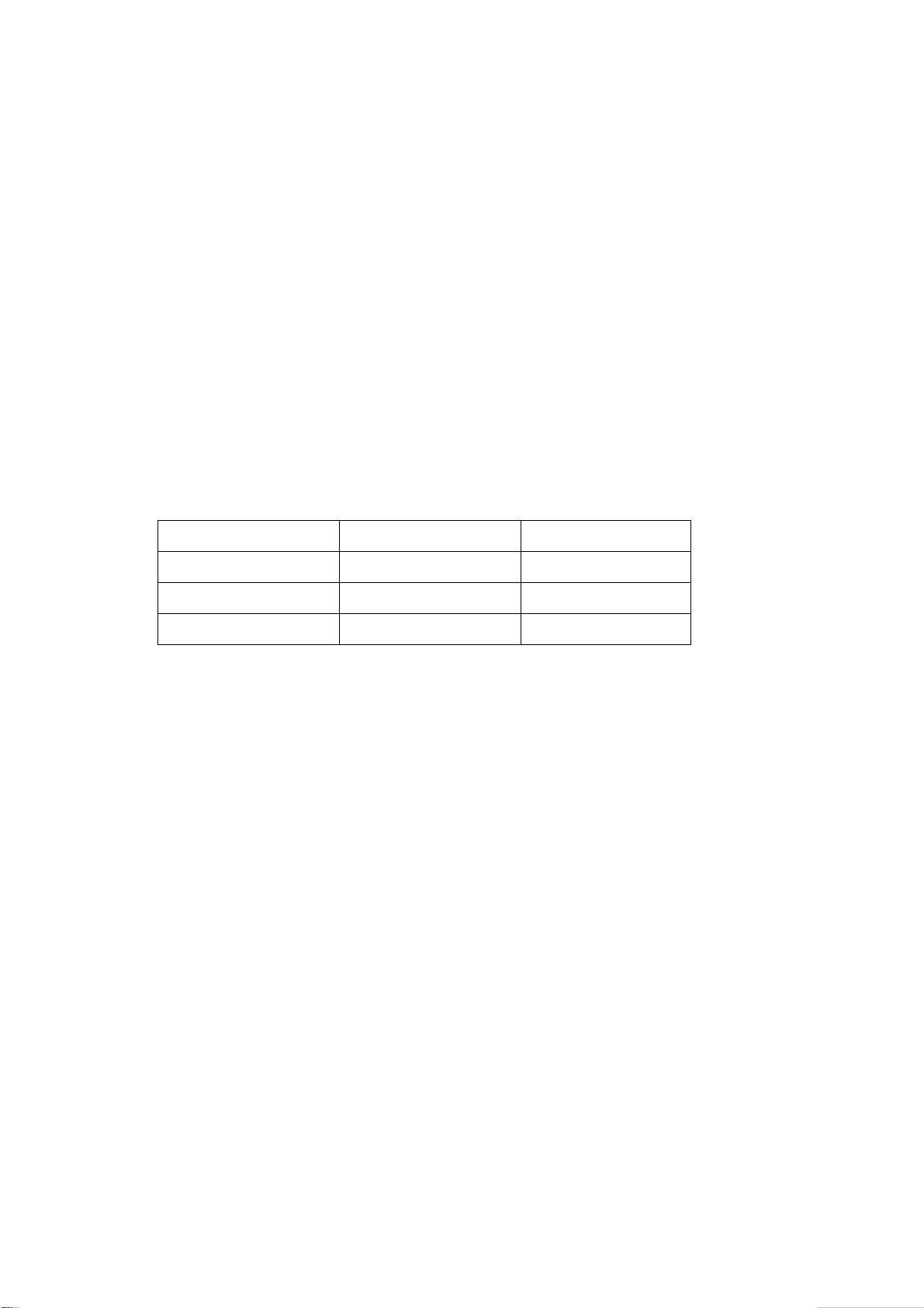
2.1 42” Plasma PDP panel:
There may appear three kinds of defective points for this model as shown in Fig.1, i.e., bright spot
(remain bright); dark spot (non-illuminating); flickering spot (continuously flickering).
However they should not exceed the specification as in table 1. Otherwise the product shall be
deemed as sub-standard.
Zone B
H
W/4 W/2 W/4
Figure 1 Defective Points
Table 1 Criterion for Three Kinds of Defective Points
Kind Area A Area B Remark
Dark spots No more than 2 No more than 8
Bright spot No more than 1 No more than 2
Flickering spot No more than 1 No more than 2
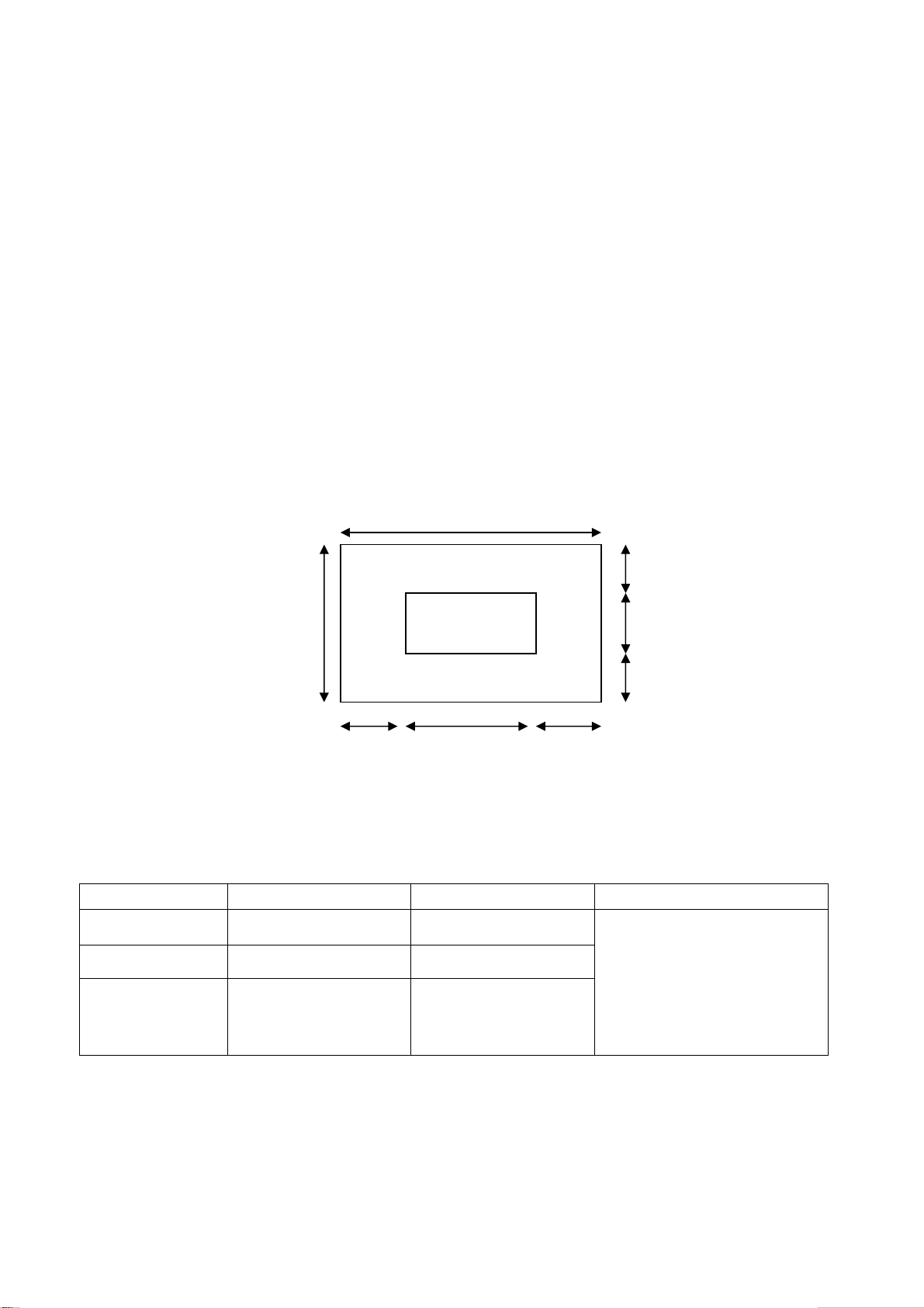
2.2 50” Plasma PDP panel:
There may appear three kinds of defective points for this model as shown in Fig.2 i.e., bright spot
(remain bright); dark spot (non-illuminating); flickering spot (remain flickering).
However they should not exceed the specification as in table 2. Otherwise the product shall be
Zone A
W
H/4
H/2
H/4
Total number of defective
points in A and B shall not
exceed 8. The distance
between two defective
points shall not be shorter
than 15mm.
3
deemed as sub-standard.
H
Zone B
Zone A
W
H/4
H/2
H/4
Item Kind Area A Area B Remark
1 Dark spots No more than 4 No more than 10
2 Bright spot No more than 1 No more than 3
W/4 W/2 W/4
Total number of defective
points in A and B shall not
exceed 14. The distance
3 Flickering spots No more than 1 No more than 3
between two defective points
shall not be shorter than
10mm.
Figure 2 Defective Points
Table 2 Criterion for Three Kinds of Defective Points
4

Alignment instructions
1. Test equipment
PM5515 (video signal generator)
VG-849 (YUV, VGA, HDMI signal generator)
CA100 (white balancer)
2. The alignment flow chart (see below figure)
Connect with central signal source, then check each function of TV such as
station missing, analog control etc., check the output of headphone and speaker
Input AV/SVIDEO signal, then check each function of all the terminals
Input HD signal (format), then check each function of the terminal
Input VGA, HDMI signal, check if the display is normal, check each
function such as analog control etc., check horizontal /vertical center etc.
3. Description of adjustment
3.1 Unit adjustment
To produce digital board and analog board
Check the accessories and pack them in box
Fig-1 adjustment flow-chart
Check DDC and FLASH
All testing
Adjust white balance
Preset ex-factory
Connect the digital processing board, analog board, power board, power filter board and button
board according to the wiring diagram. Connect with power and observe the display.
3.2 Method for using factory menu
Press ”Source” button, then press”2580” to enter level one factory menu. Press ”▲” and “▼“ to
5
select adjustment page, then press “OK” to access. Press “▲” and “▼“ to move cursor up and down,
when the cursor stays on a certain adjustment item, you can adjust it according the prompt. Press
“MENU” exit to the level one factory menu; press “MENU” again to exit from the factory menu. The
adjustment item is list as table 3.
Table 3 adjustment item
No. Item Specification
1 Factory Preset Reset to the default data
2 Spatial NR
3 Speckel NR
4 Temporal NR
5 White Balance White balance adjustment
6 Auto Color A/D correction
7 DTV Manual Scan If search DTV at manual scan, default= Off
3.3 adjustment of white balance
3.3.1 input 16 level gray-scale signal from VG849 to HDMI channel (TMIING: select a support
format of HDMI), enter white balance adjustment page of factory menu, select cool color
temperature of item, fixed GG to 5000, adjust RG, BG, let the color coordinate of third level on the
right be (270,283) at 120nits; fixed BO to 5000, adjust RO, GO, let the color coordinate of third level
on the left be (270,283) at 5nits. The brightness of 120nits and 5nits may obtain by adjusting the
contrast and brightness of menu.
Noise reduce setting, the preset data of each
channel is different, please don’t change it.
3.3.2 input 16 level gray-scale signal from VG849 to AV channel (TMIING:968), enter white balance
adjustment page of factory menu, select cool color temperature of item, fixed GG to 5000, adjust
RG, BG, let the color coordinate of third level on the right be (270,283) at 120nits; fixed BO to 5000,
adjust RO, GO, let the color coordinate of third level on the left be (270,283) at 5nits. The brightness
of 120nits and 5nits may obtain by adjusting the contrast and brightness of menu.
3.3.3 input 16 level gray-scale signal from VG849 to VGA channel (TMIING: select a support format
of VGA), enter white balance adjustment page of factory menu, select cool color temperature of
item, fixed GG to 5000, adjust RG, BG let the color coordinate of third level on the right be (270,283)
at 120nits; fixed GO to 5000, adjust RO, BO, let the color coordinate of third level on the left be
(270,283) at 5nits. The brightness of 120nits and 5nits may obtain by adjusting the contrast and
brightness of menu.
3.3.4 input 16 level gray-scale signal of 480P from VG849 to YPbPr channel, enter white balance
adjustment page of factory menu, select cool color temperature of item, fixed RG, GG, BG to 5000,
and RO to 5000, adjust RO, BO, let the color coordinate of third level on the left be (270,283) at
5nits. The brightness of 5nits may obtain by adjusting the contrast and brightness of menu.
Note: the white balance adjustment of VGA and YPBPR must be done at the situation that the white
balance adjustment of HDMI is accurate.
4 Performance check
4.1 TV function
Connect RF-TV terminal to the central signal source, enter the setup menu→ auto search, check if
there is station skipping, the output of earphone and speaker, the picture are normal. Especially
check the signal of PAL and DVB-T, check if the S/PDIF output of DVB-T is normal.
4.2 AV/S-VIDEO terminal
Input AV/S signal, check if the picture and sound are normal. The main system is NTSC and PAL.
6
4.3 YPbPr/YCbCr terminal
Input YUV signal (VG-849 signal generator), separate input YUV format signal of table 4 and check
if the picture and sound are normal.
Table 4 YUV signal format
No H-frequency (KHz) V-frequency (KHz) Signal
15.734 59.94 SDTV 480i
1
2 31.469 59.94 HDTV 480p
3 44.955 59.94 HDTV 720p
33.716 59.94 HDTV 1080i
4
15.625 50 SDTV 576i
5
31.25 50 HDTV 576p
6
37.5 50 HDTV 720p
7
4.4 VGA terminal
Input VGA signal (VG-849 signal generator), separate input VGA format signal of table 3 and check
if the picture and sound are normal. If the image is deflection of the H/V-field, select manual
correction of Advanced Video Menu.
4.5 HDMI terminal
HDMI signal format receives the 8 high-definition signals: 480I, 480P, 720P/60 Hz, 1080I/60 Hz,
576I, 576P, 720P/50Hz,1080I/50Hz except for the table 5 signal. Separate input the signals from
VG-849. Check if the image (contain HDCP ON and OFF) and sound are normal, if the output of
S/PDIF is normal.
Table 5 VGA signal format
No Resolution H-frequency(kHz) V-frenquency(Hz)
1 720 X 400 31.469 70.086 28.322 IBM
2 640 X 480 31.469 59.94 25.175 IBM
3 640 X 480 37.861 72.809 31.5 VESA
4 640 X 480 37.5 75 31.5 VESA
5 640 X 480 43.269 85.008 36 VESA
6 800 X 600 35.156 56.25 36 VESA
7 800 X 600 37.879 60.317 40 VESA
8 800 X 600 48.077 72.188 50 VESA
9 800 X 600 46.875 75 49.5 VESA
10 800 X 600 53.674 85.061 56.25 VESA
11 1024 X 768 48.363 60.004 65 VESA
12 1024 X 768 56.476 70.069 75 VESA
13 1024 X 768 60.023 75.029 78.75 VESA
Point clock pulse
frenquency(MHz)
Remark
5 Ex-factory setting of user menu
1) Select TV channel, volume: 40
2) Video menu, Picture Mode: Vivid ( other items: Mild, Custom, Standard), Aspect Ratio: Wide
3) Video menu, Advanced Video Menu:
7
Color Temperature: Cool
4) Audio menu, Audio Mode: Speech(other items: Custom, Music, Movie)
Balance: 50, SPDIF Mode: Auto, HP Volume:50
5) Rate menu, Rating: No Block, Parent Lock: off
6) System menu, State: NSW/ACT(other items: VIC, QLD, SA, WA, TAS, NT)
Note: the default password of Rate menu is”0000”
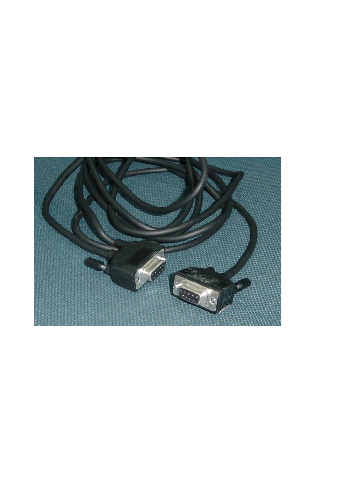
Method of software upgrading
1. Connect RS-232 cable to computer and TV set. The cable must be a female to female
RS-232 cable, and the line is TXD to RXD and RXD to TXD cross-link. It’s popular for PC to
PC connection.
2. If the computer has no RS-232 serial port(e.g. Notebook PC),you needs a additional USB to
serial port cable.
8
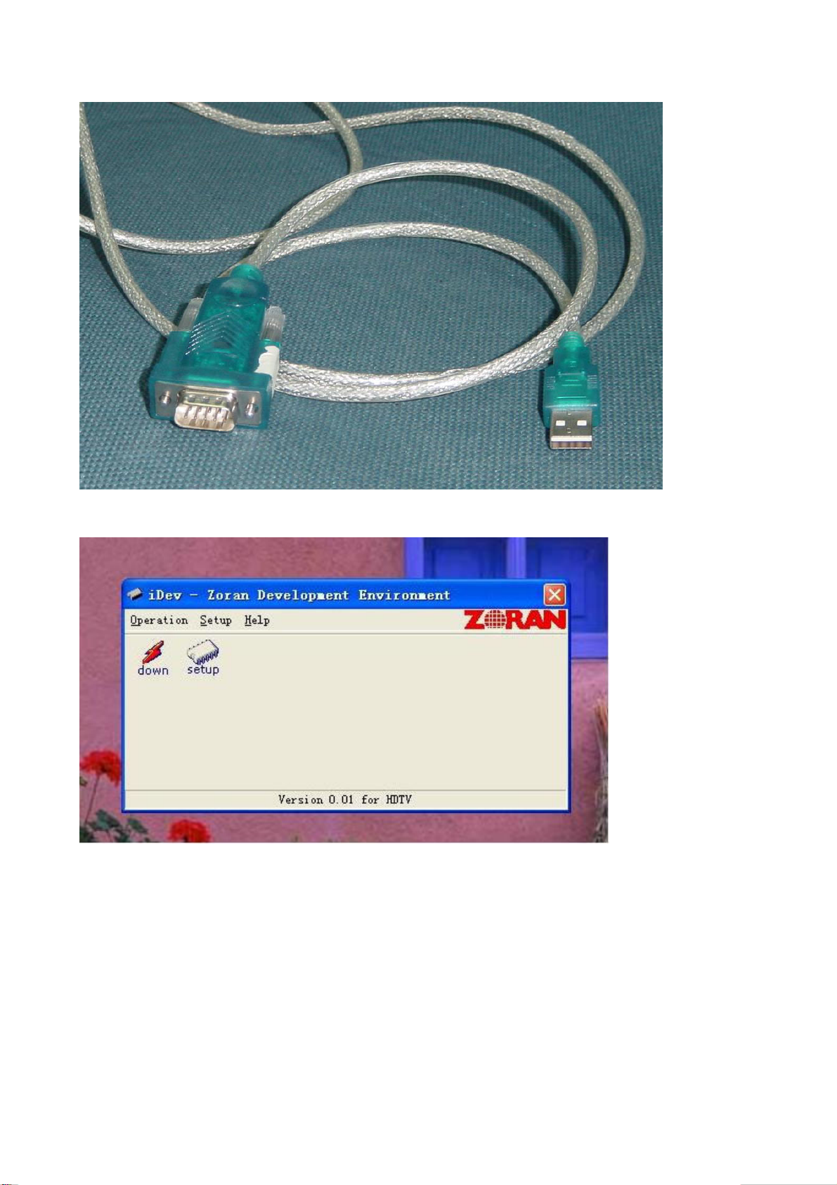
3. Copy the update tools (iDev.exe) to the path you want to do it, and double click it.
4. Select “setup” menu.
9
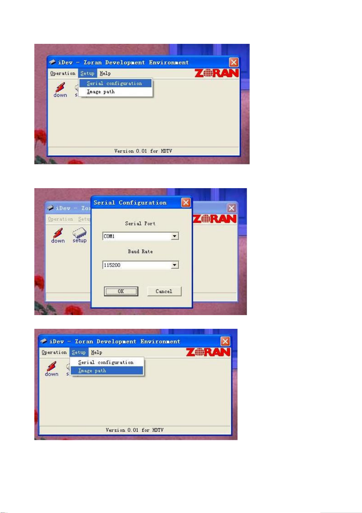
5. Confirm the Serial port is right. Base on the port which using for update. And set the band rate to
115200 (default).
6. Select the “Image path” menu.
10
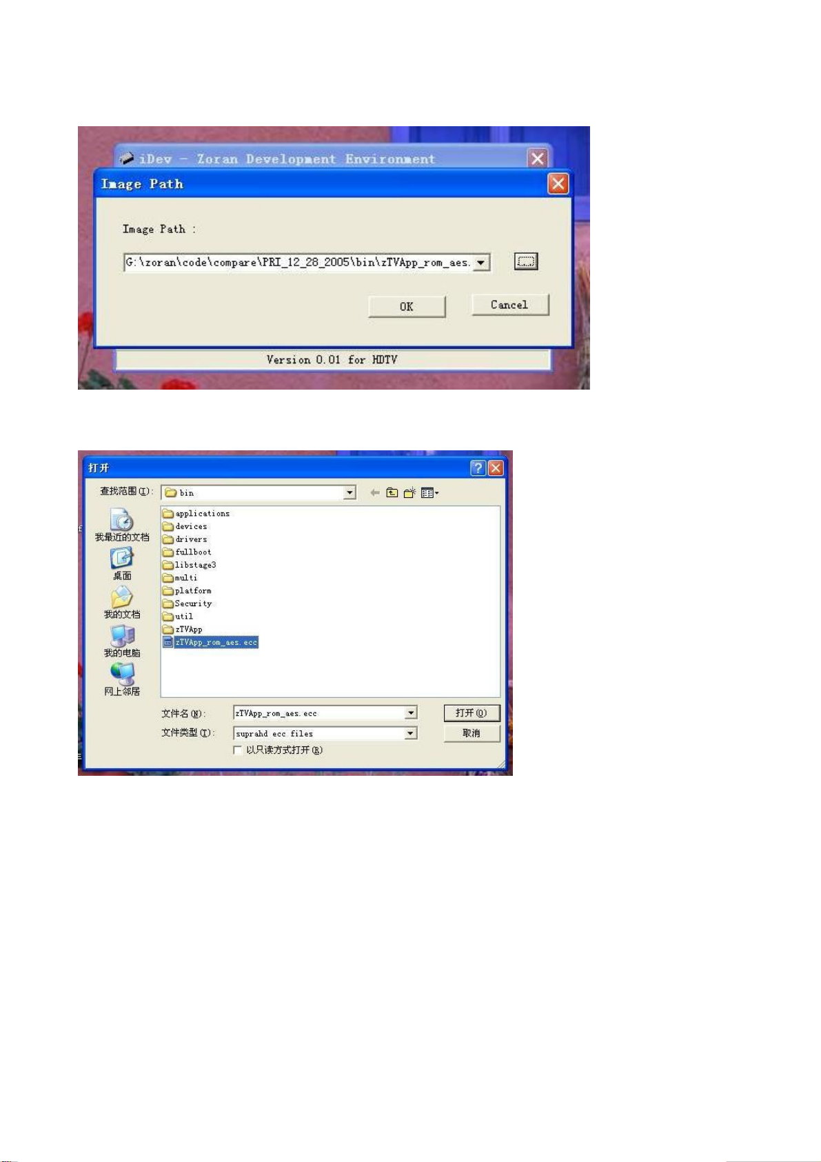
7. Confirm it’s the right file.
8. If it’s not right(Maybe you didn’t select it before),click the “…”button to select “*.ecc” file.
Sometimes the image file you got it will be “*.rar ”or “*.zip” zip file, needs unzip it first.
9. You also can click the setup button to select and config, but please don’t select the red
one(update boot sector).
11
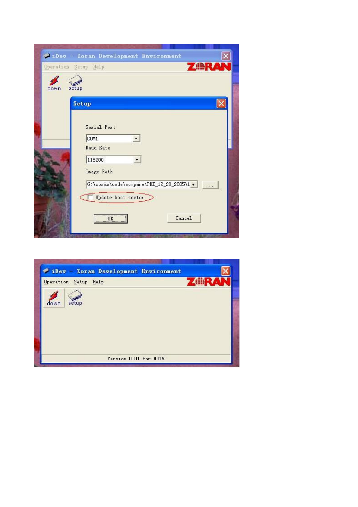
10. Then click the “down” button.
12
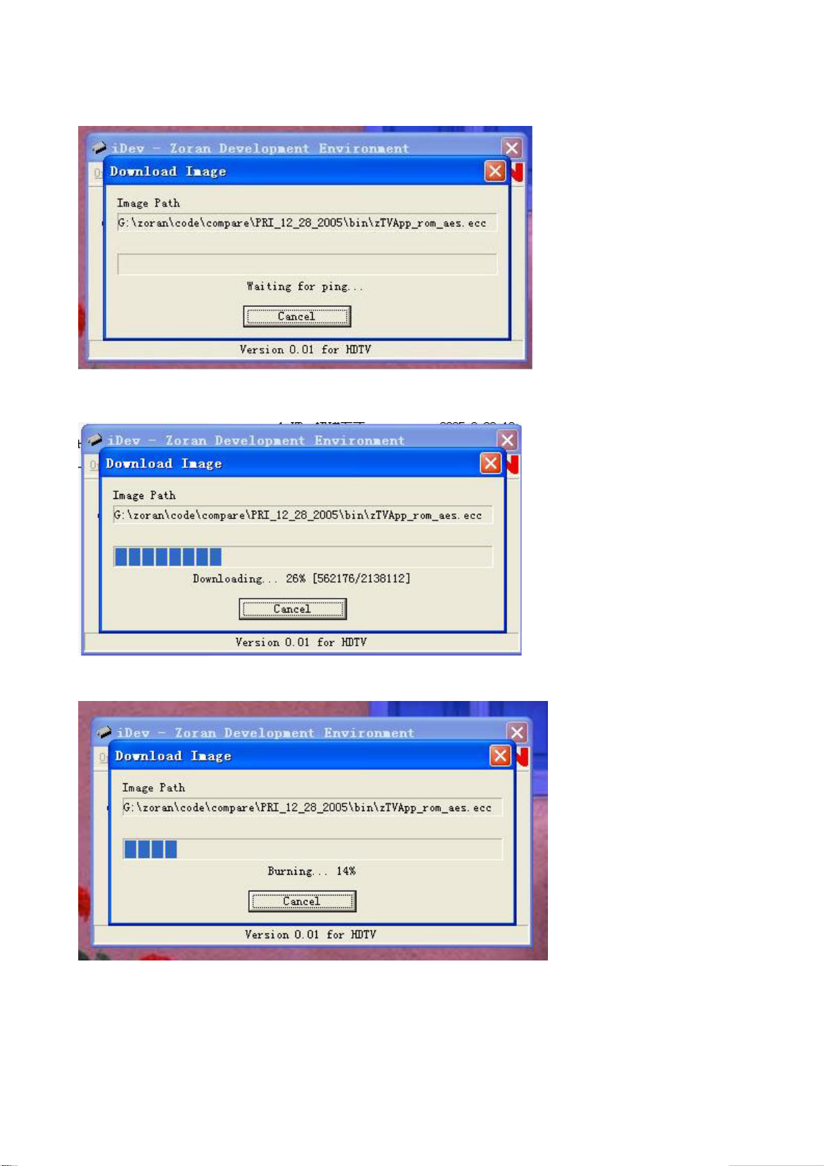
11. You can see the “waiting” window.
12. Then power (off then) on the TV set.
13. After download, it will be burning.
13