

Etec EX202DS Installation Manual
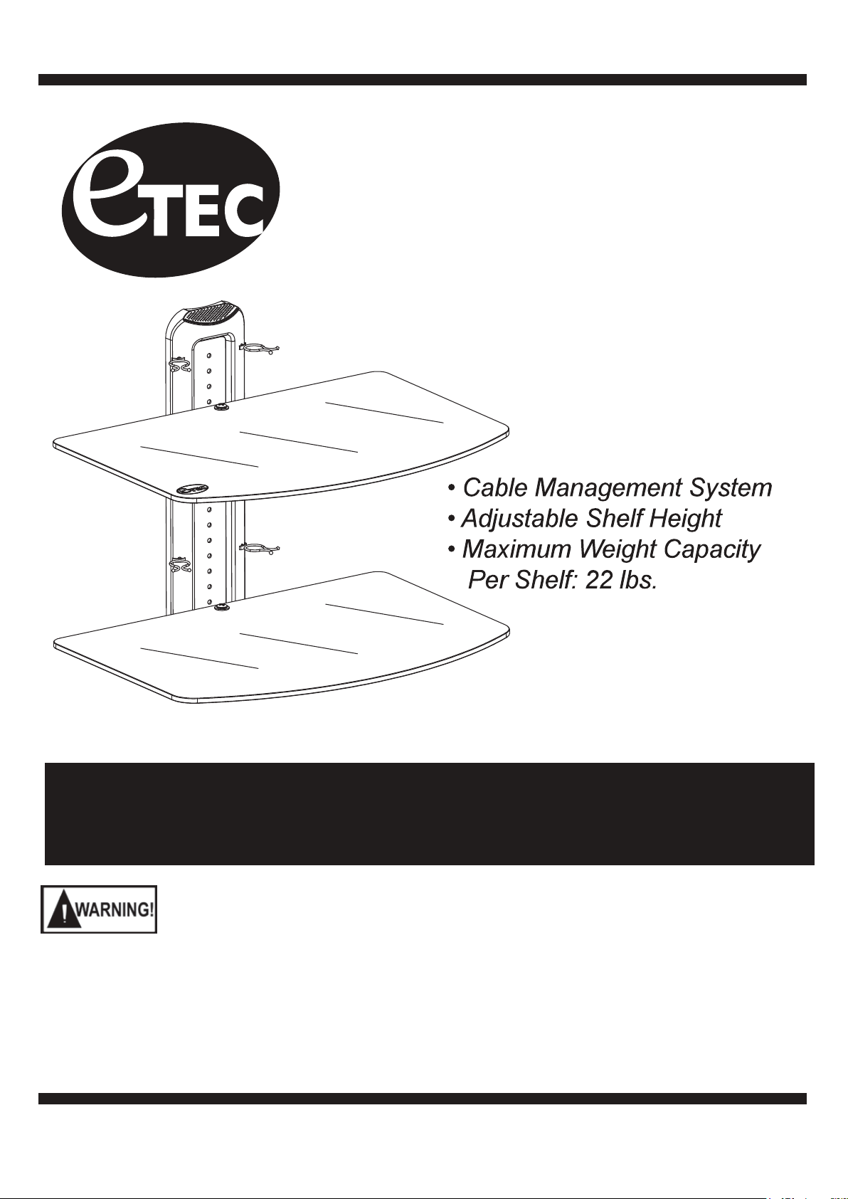
Two Shelf, Wall Mounted
A/V Component Stand
Installation Guide
Model: EX202DS
For technical assistance or troubleshooting
please call 1-855-994-3832.
This product is intended for use only with Audio/Video components (Not for use with any type of TV). The maximum weight
capacity per shelf is 22 lbs. See apparatus instructions. Using with an apparatus heavier than the maximum shelf support
weight indicated may result in instability and cause personal injury.
READ THIS FIRST
Read this entire manual! Do not attempt to install this product if you do not understand the instructions. Contact a qualified
mount installer if you have any doubts about a safe and secure mount installation, or if you are not sure what specific wall
materials you are attaching this mount to. Check all the parts carefully to make sure there are no missing or damaged parts.
Improper installation may result in damage to your Components, TV, property, and personal injury.
This product is intended only to be used to support Audio/Video Components (DVD players,
Cable boxes, 5.1 Sound syste .noisiveleT fo epyt yna rof dnats siht esu ton oD ).cte ,sm
Use with components heavier than the maximum shelf weight capacity can damage equipment and
cause personal injury.
Schoenfeld International Inc. and ETEC are not responsible for personal injury or product
damage due to mishandling, incorrect mounting, incorrect assembly, or incorrect use of this
oduct.
pr
CHILD SAFETY
How and where you use your A/V Component Wall Mount Stand is extremely important for Child Safety
As you set up and use your new product, keep all of these safety tips in mind.
One size of A/V Component Stand does not support all components weights and sizes.•
Your A/V Component Stand assembly instructions contains specific information on the maximum weight •
capacity per shelf that your A/V Component Sta
support weight for each shelf.
Carefully read all of enclosed instructions for proper use of this product. If you have any doubts about •
safe and secure assembly, please contact a professional.
Don’t let children climb on or play next to Wall Mounted A/V Stands or TV Wall Mounts.•
Remember that children can become excited while watching a program, especially on a “larger than •
life” TV. Make sure to place or install the A/V Component
or knocked down.
Make sure that you safely route all cords and cables so that they cannot be pulled or grabbed by curious •
children.
nd can safely support. Do not exceed the maximum
Stand where it cannot be pushed, pulled on,
Always wear safety goggles to when drilling or installing hardware.
Tools
For your convenience, we have included an allen wrench and a socket tool with this mount. For the best assembly experience and mounting safety, we always recommend using full-size tools for each assembly steps.
Below is a recommended tool list you will need for proper and safe installation. See applicable warnings
in this manual about certain types of mounting surface materials and the special hardware and tools that
should be used.
• Drill with a specific size drill bit to pre-drill holes in the wall
• Stud finder
• Tape measure
• Pencil
• Screw drivers
• Socket wrenches
• Small hammer
• Safety goggles
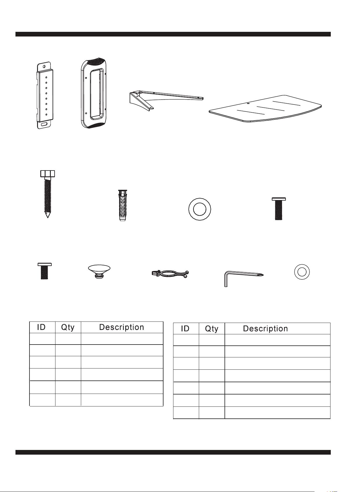
x1
1
2
x1
x2
3
x24
Wall Plate
x2
A
Long Bolts
x4
E
M6x8mm
Bolts
Plastic Cover
x2
B
Concrete Anchors Long Bolt Washers
F
x8
Glass Shelf
Suction Pads
Shelf Support
x2
C
G
x8
Cable Management
Clips
Glass Shelves
*The shelf with the ETEC
logo is the top shelf.
x2
D
M6x12mm
Shelf Security Bolts
x1
H
Allen Wrench
with Phillips End
x2
I
Washer
1 1
2 1
3 2
4 2
A
B
Wall Plate
Plastic Cover
Shelf Support
Glass Shelf
2
2
Long Bolts
Concrete Anchors
C
D
E
F
G
H
2
2
4
8
8
1
Long Bolt Washers
Shelf Security Bolt
M6x8mm Bolts
Glass Shelf Suction Pads
Cable Management Clips
Allen Wrench
WasherI 2
3
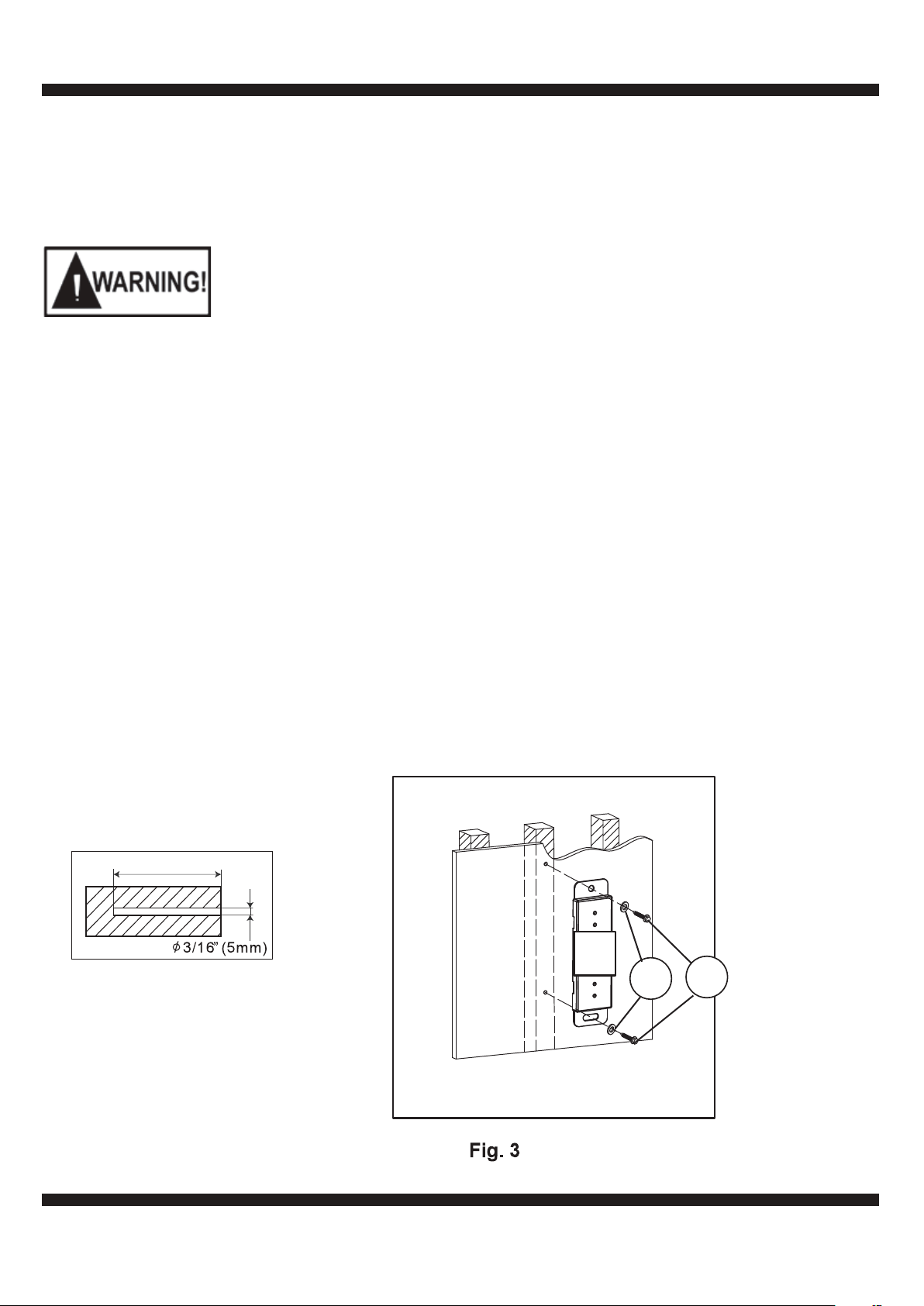
Step 1: Install the Wall Plate
Read the instructions. Determine the proper location for your wall type. Make sure the mounting location
has enough space for the Glass Shelf (4) and the Wall Plate (1). Follow the mounting instructions for
wood studs or concrete wall installation.
Do not attach this A/V Component Stand to any wall with Brick or steel stud construction.
Attaching this mount to wood or concrete walls requires special tools and hardware to
ensure the mount is securely and safely attached to these materials. Brick and concrete
will break or crumble if special concrete drill bits and drill operating speeds are not properly
used. Consult a professional if you are unsure or have any doubts
about the safely of the
installation. Personal injury or equipment damage can result if the mount is not properly
installed.
Wood stud walls (Fig 1):
1. Use an electronic stud finder to locate the wall studs. Mark their locations on the wall.
2. Place the Wall Plate (1) flat against the wall in the desired mounting location, aligning the mounting
holes on the bracket with the studs. Use the Wall Plate (1) as a template to mark the mounting holes
on the wall.
3. Use 3/16” (5mm) drill bit to pre-drill holes at least 2.5” inches (65mm) deep at the marked locations.
4. Use the Long Bolts (A) and Long Bolt Washers (C) to mount the Wall Plate (1) to the wall as shown
in Fig. 3. Do not use wall anchors in wood stud walls.
5. Use a level to make sure the Wall Plate (1) is perfectly straight and securely tighten the Long Bolts (A)
using a proper size wrench. Make sure to tighten the top bolt first, then re-check the level before
tightening the bottom bolt.
2-1/2” (65mm)
1
C
A
4
 Loading...