

Page 1

CD-RADIO RECORDER WITH DIGITAL
DISPLAY AM/FM TUNER
OPERATING INSTRUCTIONS
8-WAY
SPEAKER
SYSTEM
DIGITAL
READOUT
TUNER
DX
DBBS
BASS
BOOSTER
MODEL : CD9900
DATE : 6 JULY, 2007
MODEL CD9900 “eTEC”
ENGLISH I/M FOR APPROVAL
SIZE : 102 (W) X 136 (H) MM FOR EACH PAGE
PRINTING COLOR : BLACK
E-2
CAUTION: INVISIBLE LASER RADIATION WHEN OPEN AND INTERLOCKS DEFEATED.
AVOID EXPOSURE TO BEAM.
VORSICHT: UNSICHTBARE LASERSTRAHLUNG TRITT AUS, WENN DECKEL
GEÖFFNET UND WENN SICHERHITSVERRIEGELUNG ÜBERBRÜCKT IST.
NICHT DEM STRAHL AUSSETZEN.
VARNING: OSYNLIG LASERSTRÁLNING NÄR DENNA DEL ÄR ÖPPNAD OCH SPÄRR
ÄR URKOPPLAND. STRÁLEN ÄR FARLIG.
ADVARSEL: USYNLIG LASERSTRÁLING VED ÁBNING. NÁR
SIKKERHEDSAFBRYDERE ER UDE AF FUNKTION. UNDGÁ UDS/ETTELSE FOR
STRÁLING.
ATTENZIONE: RADIONS LASER INVISIDILE. NON GUARDARE DIRETTAMENTE
NELLA SORGENTE DEL LASER.
ACHTUNG: LASERLINSE NICHT BERÜHREN UNSICHTBARER LASERSTRAHL.
AVISO: A LENTE NUNCA DEVE SER TOCADA.
CAUTION: GROUNDING OR POLARIZATION. THE PRECAUTIONS SHOULD BE
TAKEN SO THAT THE WIDER BLADE OF THE AC PLUG MUST MATCH THE SLOT
IN RECEPTACLE "WALL SOCKET".
WARNING: To reduce
the risk of electric shock, do
not remove cover (or back).
No user-serviceable
parts inside. Refer
servicing to qualified
service personnel.
CAUTION
RISK OF ELECTRIC SHOCK
DO NOT OPEN
The exclamation
point within the
triangle is a warning
sign alerting you of
important instructions
accompanying the
product.
The lightning flash
and arrowhead
within the triangle
is a warning
sign alerting you of
"dangerous voltage"
inside the product.
WARNING:
TO REDUCE THE RISK OF FIRE OR ELECTRIC SHOCK, DO NOT
EXPOSE THIS APPLIANCE TO DRIPPING OR SPLASHING LIQUIDS.
CLASS 1 LASER PRODUCT
KLASSE 1 LASER PRODUKT
LASER DE CLASSE
LASER DI PRIMA CLASSE
KLASSE 1 LASER
LASER PRIMERA CLASE
LASER CLASSE 1
KLASSE 1 LASER PRODUKT
CAUTION
DO NOT EXPOSE TO DRIPPING OR SPLASHING LIQUIDS!
CAUTION : TO PREVENT ELECTRIC SHOCK, MATCH WIDE BLADE OF
PLUG TO WIDE SLOT, FULLY INSERT.
ATTENTION: POUR ÉVITER LES CHOC ÉLECTRIQUES, INTRODUIRE
LA LAME LA PLUS LARGE DE LA FICHE DANS LA BORNE
CORRESPONDANTE DE LA PRISES ET POUSSER JUSQU' AU FOND.
Page 2
E-3
1. READ INSTRUCTIONS - All the safety and operating instruction should be read before the product
is operated.
2. RETAIN INSTRUCTIONS - The safety and operating instruction should be retained for future
reference.
3. HEED WARNINGS - All warning on the product and in the operating instructions should be adhered to.
4. FOLLOW INSTRUCTIONS - All operating and use instructions should be followed.
5. CLEANING - Unplug this product from the wall outlet before cleaning. Do not use liquid cleaners or
aerosol cleaners. Use a damp cloth for cleaning.
6. ATTACHMENTS - Do not use attachments not recommended by the product manufacturer as they
may cause hazards.
7. WATER AND MOISTURE - Do not use this product near water- for example, near a bath tub,
wash bowl, kitchen sink, or laundry tub, in a wet basement, or near a swimming pool, and the like.
8. ACCESSORIES - Do not place this product on an unstable cart, stand, tripod, bracket, or table.
The product may fall, causing serious injury to a child or adult, and serious damage to the product.
Use only with a cart, stand, tripod, bracket, or table recommended by the manufacturer, or sold with
the product. Any mounting of the product should follow the manufacturer's instructions, and should
use a mounting accessory recommended by the manufacturer.
9. A product and cart combination should be moved with care. Quick stops,
excessive force, and uneven surfaces may causethe appliance and cart
combination to overturn.
10. VENTILATION - Slots and openings in the cabinet are provided for ventilation
and to ensure reliable operation of the product and to protect it from
overheating, and these openings must not be blocked or covered. The openings should never be
blocked by placing the product on a bed, sofa, rug, or other similar surface. This product should
not be placed in a built-in installation such as a bookcase or rack unless proper ventilation is
provided or the manufacturer's instruction have been adhered to.
11. POWER SOURCES - This product should be operated only from the type of power source indicated
on the marking label. If you are not sure of the type of power supply to your home, consult your
product dealer or local power company. For products intended to operate from battery power, or
other sources, refer to the operating instruction.
12. GROUNDING OR POLARIZATION - This product may be equipped with a polarized
alternating-current line plug (a plug having one blade wider than the other). This plug will fit into the
power outlet only one way. This is a safety feature. If you are unable to insert the plug fully into the
outlet, try reversing the plug. If the plug should still fail to fit, contact your electrician to replace your
obsolete outlet. Do not defeat the safety purpose of the polarizes plug.
ALTERNATE WARNINGS - This product is equipped with a three-wire grounding-type plug, a plug
having a third (grounding) pin. This plug will only fit into a grounding-type power outlet.
This is a safety feature. If you are unable to insert the plug into the outlet, contact you electrician to
replace your obsolete outlet. Do not defeat the safety purpose of the grounding-type plug.
13. POWER-CORD PROTECTION - Power supply cords should be routed so that they are not likely to
be walked on or pinched by items placed upon or against them, paying particular attention to cords
at plugs, convenience receptacles, and point where they exit from the product.
IMPORTANT SAFETY INSTRUCTIONS
14. PROTECTIVE ATTACHMENT PLUG - The product is equipped with an attachment plug having
overload protection. This is a safety feature. See Instruction Manual for replacement or resetting
of protective device. If replacement of the plug is required, be sure the service technician has used
a replacement plug specified by the manufacturer that has the same overload protection as the
original plug.
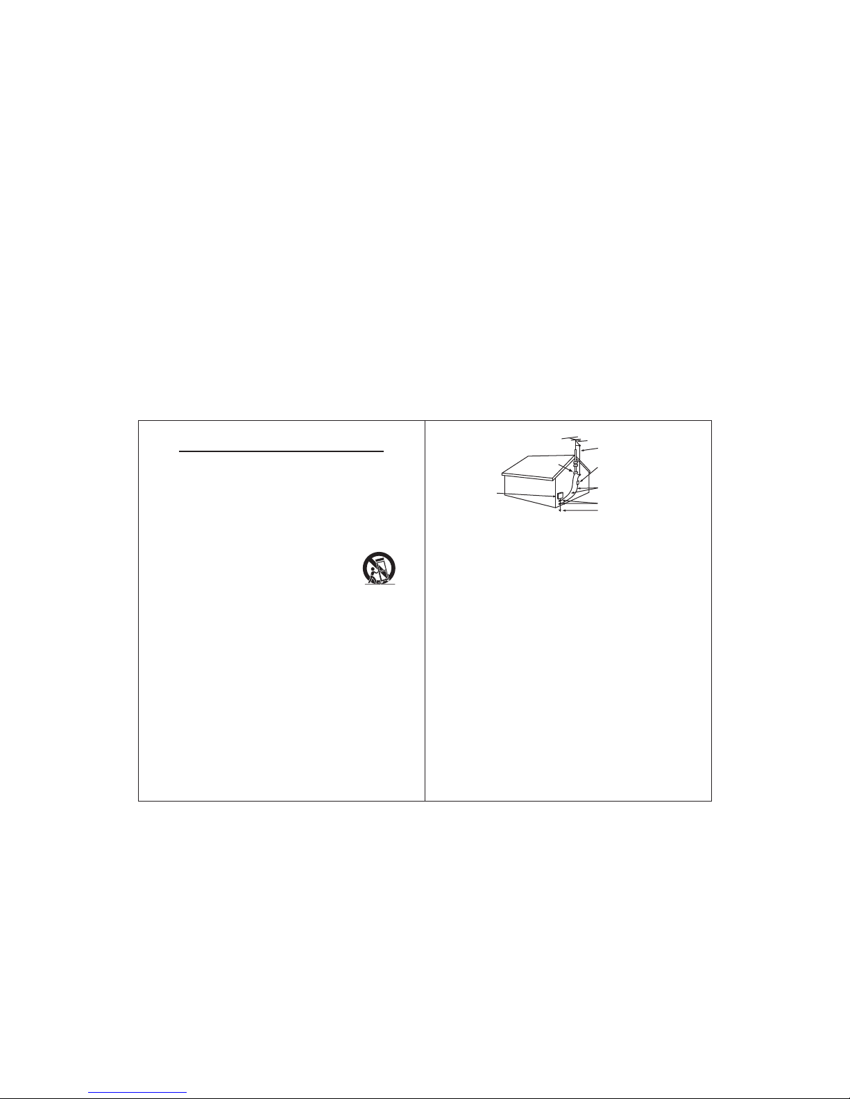
15. OUTDOOR ANTENNA GROUNDING - If an outside antenna is connected to the receiver, be sure
the antenna system is grounded so as to provide some protection against voltage surges and
built-up static charges. Article 810 of the National Electrical Code, ANSI/NFPA 70, provides
information with regard to proper grounding of the mast and supporting structure, grounding of the
mast and supporting structure, grounding of the lead-in wire to an antenna-discharge unit, size of
grounding conductors, location of antenna-discharge unit, connection to grounding electrodes,
and requirements for the grounding electrode.
E-4
SEE FIGURE:
NEC - NATIONAL ELECTRICAL CODE
GROUND
CLAMP
ANTENNA
LEAD IN WIRE
ANTENNA
DISCHARGE UNIT
(NEC SECTION 810-20)
GROUNDING CONDUCTORS
(NEC SECTION 810-21)
GROUND CLAMPS
ELECTRIC
SERVICE
EQUIPMENT
POWER SERVICE GROUNDING
ELECTRODE SYSTEM
(NEC ART 250, PART H)
16. LIGHTNING - For added protection for this product during a lightning storm, or when it is left
unattended and unused for long periods of time, unplug it from the wall outlet and disconnect the
antenna or cable system. This will prevent damage to the product due to lightning and power-line
surges.
17. POWER LINES - An outside antenna system should not be located in the vicinity of overhead
power lines or other electric light or power circuits, or where it can fall into such power lines or
circuits. When installing an outside antenna system, extreme care should be taken to keep from
touching such power lines or circuits as contact with them might be fatal.
18. OVERLOADING - Do not overload wall outlets, extension cords, or integral convenience
receptacles as this can result in a risk of fire or electric shock.
19. OBJECT AND LIQUID ENTRY - Never push objects of any kind into this product through openings
as they may touch dangerous voltage points or short-out parts that could result in a fire or electric
shock. Never spill liquid of any kind on the product.
20. SERVICING - Do not attempt to service this product yourself as opening or removing covers may
expose you to dangerous voltage or other hazards, Refer all servicing to qualified service personnel.
21. DAMAGE REQUIRING SERVICE - Unplug this product from the wall outlet and refer servicing to
qualified service personnel under the following conditions:
a) When the power-supply cord or plug is damaged,
b) If liquid has been spilled, or objects have fallen into the product,
c) If the product has been exposed to rain or water,
d) If the product does not operate normally be following the operating instructions. Adjust only
those controls that are covered by the operating instructions as an improper adjustment of
other controls may result in damage and will often require extensive work by a qualified
technician to damage and will often require extensive work by a qualified technician to restore
the product to its normal operation.
e) If the product has been dropped or damaged in any way, and
f ) When the product exhibits a distinct change in performance this indicates a need for service.
22. REPLACEMENT PARTS - When replacement parts are required, be sure the service technician
has used replacement parts specified by the manufacturer or have the same characteristics as the
original part. Unauthorized substitutions may result in fire, electric shock, or other hazards,
23. SAFETY CHECK - Upon completion of any service or repairs to this product, ask the service
technician to perform safety checks to determine that the product is in proper operating condition.
24. WALL OR CEILING MOUNTING - The product should be mounted to a wall or ceiling only as
recommended by the manufacturer.
25. HEAT - The product should be situated away from heat sources such as radiators, heat registers,
stoves, or other products (including amplifiers) that produce heat.
Page 3
25
26
27
24
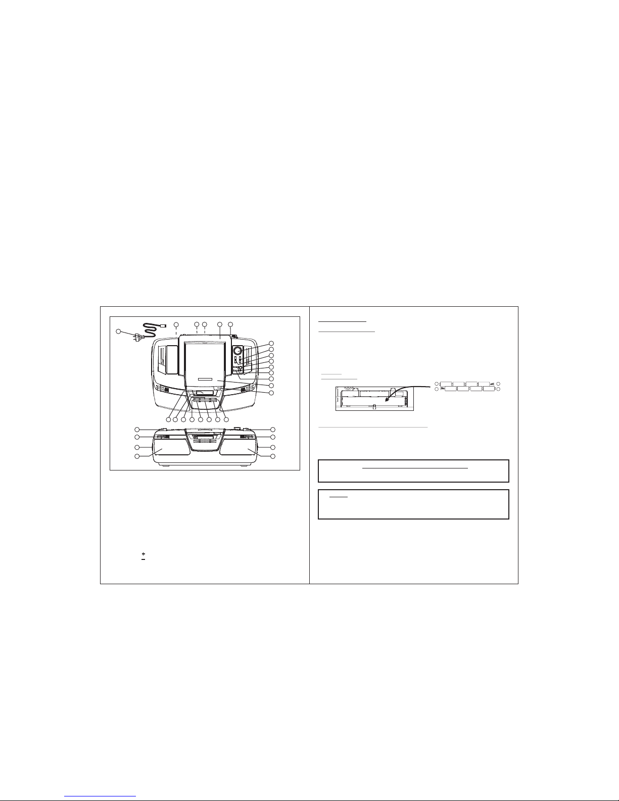
LOCATION OF CONTROLS
E-5
1.
2.
3.
4.
5. CARRYING
6.
7.
9.
10. BASS-BOOST (DBBS) KEY
11. BASS-BOOST (DBBS) LED LIGHT
12. VOLUME ( )
AC POWER CORD AND PLUG
AC-SOCKET (REAR OF UNIT)
HEADPHONES(EARPHONES) SOCKET
BATTERY DOOR COMPARTMENT
(UNDER THE UNIT)
HANDLE
TELESCOPIC ANTENNA
TUNING KNOB
8. BAND SWITCH (AM/FM/FM ST.)
FUNCTION SWITCH
[OFF/ RADIO/ CD/ AUX]
KEY
13. VOLUME ( )KEY
14. CD DOOR
15. CD DOOR FINGER GRIP
16. MULTIFUNCTION DIGITAL LCD DISPLAY
17. FM STEREO LED LIGHT
18. CD "PLAY/ PAUSE" KEY
19. CD "BACK" KEY
20. CD REPEAT KEY
21. CD "STOP" KEY
22. CD PROGRAM KEY
23. CD "NEXT" KEY
24. TOP SPEAKERS (LEFT & RIGHT)
25. FRONT TWEETERS (LEFT & RIGHT)
26. SIDE SPEAKERS (LEFT & RIGHT)
27. MAIN SPEAKERS (LEFT & RIGHT)
E-6
13
8
25
26
27
24
3
6
4
5
2
1
POWER SUPPLY
BATTERY OPERATION
- OPEN THE BATTERY DOOR AND INSERT 8 PCS "C-CELL" (UM-2/ LR14 TYPE)
BATTERIES. PLEASE OBSERVE CORRECT BATTERY POLARITIES OR THE SET WILL
NOT WORK.
- IMPORTANT: WHEN THE SET IS ONLY USED WITH AC, OR IS NOT USED FOR 2 WEEKS
OR MORE, PLEASE REMOVE THE BATTERIES, TO AVOID DAMAGE TO THE SET FROM
LEAKAGE OF BATTERIES.
BATTERY
COMPARTMENT:
AC OPERATION (BUILT-IN TRANSFORMER)
- MAKE SURE THE SET VOLTAGE OF THE UNIT MATCHES YOUR LOCAL HOUSEHOLD
VOLTAGE.
- INSERT THE TAIL END OF THE AC-CORD INTO THE AC-SOCKET AT THE REAR OF THE
UNIT. MAKE SURE THE TAIL END IS FULLY INSERTED.
- INSERT THE PLUG OF THE AC-CORD INTO A WALL OUTLET WITH AC-POWER.
UM-2/"C"/LR14
(1.5V) SIZE x 8 PCS.
+
-
+
-
IMPORTANT: HOW TO TELL IF POWER IS "ON" ?
WHEN THE POWER IS "ON" THE ENTIRE DIGITAL DISPLAY WILL BE LIT UP WITH
A 'BLUE" BACK-LIGHT. THIS INDICATES THE SET IS SWITCHED "ON".
7
9
10
11
12
PLEASE MAKE SURE THE TAIL END OF THE AC-CORD
IS FULLY AND PROPERLY INSERTED INTO THE AC-SOCKET AT THE REAR OF
THE UNIT. IF IT IS NOT FULLY INSERTED, THE UNIT MAY NOT FUNCTION OR
MAY STOP WORKING SUDDENLY.
NOTE:
14
18
19
20
212223
1716
15
Page 4

E-7
E-8
THE BUILT IN "SUPER BASS BOOSTER" CIRCUIT PROVIDES A POWERFUL
ENHANCEMENT TO LOW FREQUENCY MUSIC, GIVING A STRONGER BASS SOUND
WHICH IS IDEAL FOR "ROCK" OR "JAZZ" MUSIC.
- SET THE FUNCTION SWITCH TO "RADIO" AND THE BAND SELECTOR SWITCH TO THE
DESIRED BAND.
- ROTATE TUNING KNOB TO TUNE-IN THE DESIRED STATION. AS DISPLAYED IN THE
LCD DIGITAL DISPLAY.
- ADJUST THE TELESCOPIC ANTENNA AND POSITION OF THE SET TO OBTAIN THE
BEST RECEPTION.
- ADJUST THE VOLUME KNOB TO THE DESIRED LEVEL.
- TO TURN OFF THE RADIO, SLIDE THE FUNCTION SWITCH TO "OFF" POSITION,
WITHOUT ANY TAPE BUTTON PRESSED.
SUPER BASS (DBBS) FINCTION
OPERATION OF RADIO
- WHEN OPENING THE CD-DOOR, ALWAYS ENSURE THE DISC IS NOT IN MOTION (NOT
SPINNING) WHEN YOU OPEN THE CD-DOOR. ALWAYS PRESS CD "STOP" BUTTON TO
STOP THE DISC SPINNING FIRST.
- PLACE A CD INTO THE COMPARTMENT WITH THE LABEL-SIDE (PRINTED SIDE OF
DISC) FACING UPWARDS. PRESS DOWN IN THE CENTER PART OF DISC UNTIL THE
DISC "LOCKS" ONTO THE CENTER SPINDLE.
- WHEN THE CD HAS BEEN PLACED ONTO THE CENTER SPINDLE, GENTLY LOWER
THE CD-DOOR DOWNWARDS UNTIL IT LOCKS SHUT.
- THE CD IS NOW READY TO BE PLAYED.
- TO REMOVE A DISC, FOLLOW THE SAME PROCEDURE AS DESCRIBED ABOVE,
EXCEPT TO REMOVE THE CD INSTEAD OF INSERTING IT INTO THE COMPARTMENT,
BY PLACING ONE FINGER AT THE MIDDLE OF DISC (CENTER SPINDLE) & THE OTHER
AT THE EDGE OF THE DISC & GENTLY PULLING UPWARDS.
- IMPORTANT : ALWAYS HOLD A CD BY ITS EDGES. AVOID GETTING ANY FINGER
PRINTS, SMUDGES OR DIRT ONTO THE SURFACE OF A DISC. IN CASE THIS
HAPPENS, USE A SPECIAL CD-CLEANING CLOTH OR CLEANING KIT TO REMOVE THE
DIRT OR SMUDGES.
INSERTION & REMOVAL OF DISCS
- AT ANYTIME DURING PLAYBACK, PRESS THE "STOP" BUTTON TO STOP
OPERATION OF THE SET. THIS WILL RESET THE CD PLAYER TO THE FIRST TRACK (IF
YOU PRESS PLAY AFTER STOP, THE FIRST TRACK WILL ALWAYS START PLAYING).
- AT ANYTIME DURING PLAYBACK, "PRESS AND RELEASE" THE BACK/NEXT
BUTTONS : OR TO SKIP BACKWARDS OR FORWARDS BY ONE TRACK, AS
DESIRED.
- AT ANYTIME DURING PLAYBACK, "PRESS AND HOLD" THE BACK/NEXT
BUTTONS : OR TO FAST-REVERSE (REVIEW) OR FAST-FORWARD (CUE)
THE SPECIFIC TRACK, WHICH IS CURRENTLY PLAYING.
- AT ANYTIME DURING PLAYBACK, PRESS THE "CD REPEAT BUTTON" AS FOLLOWS:
PRESS ONCE = DISPLAY IS FLASHING, TO REPEAT THE CURRENT TRACK
PRESS TWICE = TO REPEAT ALL TRACKS (FULL CD)
PROGRAMMING THE CD PLAYER
- THE CD PLAYER CAN BE PROGRAMMED TO PLAY ANY SEQUENCE OF UP TO
20 TRACKS, AS DESIRED.
- ALWAYS PRESS THE STOP SWITCH BEFORE STARTING THE PROGRAMMING.
- PRESS THE PROGRAM BUTTON. THE DISPLAY WILL SHOW "01" AND THE
"PROGRAM"SYMBOL WILL BE SHOWN FLASHING, TO INDICATE THAT THE
SET IS NOW IN "MEMORY PROGRAMMING MODE", AT THE FIRST MEMORY POSITION.
- REPEAT THE PREVIOUS 2 STEPS, EACH TIME SELECTING ANY TRACK NUMBER
OF YOUR CHOICE TO BE STORED IN THE SUCCESSIVE MEMORY (PROGRAM)
POSITIONS.
- WHEN YOU PRESS THE DISPLAY WILL ADVANCE TO
THE NEXT MEMORY POSITION (eg. "02").
THE PROGRAM BUTTON
- PRESS THE BACK/NEXT SWITCHES OR TO SELECT THE TRACK (SONG)
NUMBER YOU WISH TO BE STORED IN THE FIRST MEMORY (PROGRAM)
POSITION, AND PRESS THE PROGRAM BUTTON TO CONFIRM YOUR SELECTION.
- AFTER EACH TRACK NUMBER, REMEMBER TO PRESS THE PROGRAM BUTTON.
- AFTER A MAXIMUM OF 20 SONGS (OR LESS) HAVE BEEN SELECTED AS
DESCRIBED ABOVE, PRESS THE PLAY BUTTON.
"PROG"
- THE "PROGRAM" SYMBOL WILL REMAIN "ON" TO INDICATE THAT YOU
HAVE SAVED A PROGRAM-MEMORY (SEQUENCE).
- PRESSING PLAY STARTS PLAY BACK OF THE "SAVED SEQUENCE" IN
THE PROGRAM MEMORY.
- TO CLEAR (CANCEL) THE ENTIRE PROGRAM WHICH IS STORED IN THE MEMORY,
SIMPLY PRESS "STOP" , OR SWITCH "OFF" THE SET.
"PROG"
NORMAL CD OPERATION
- INSERT A NORMAL MUSIC CD AS DESCRIBED.
- SLIDE THE FUNCTION SWITCH TO "CD".
- THE CD WILL SPIN MOMENTARILY AND THEN THE DISPLAY WILL SHOW THE T OTAL
NUMBER OF T RACKS (SONGS) OF T HE DISC.
- PRESS THE PLAY/PAUSE BUTTON . THE DISC WILL START SPINNING & THE
FIRST SONG (TRACK) WILL START PLAYING. THE DISPLAY WILL INDICATE THE
CURRENT TRACK NO. ("1" IF IT IS THE FIRST TRACK).
- AT ANYTIME DURING PLAYBACK, PRESS THE "PLAY/PAUSE" BUTTON TO PAUSE
OPERATION OF THE UNIT. PRESS PLAY/PAUSE BUTTON TO RESUME OPERATION AT
THE SAME TRACK & POSITION.
Page 5

E-9
POWER SUPPLY : .................................... AC 120V , 60Hz
DC 12V (8 x C-CELL/ UM-2/ LR14)
(BATTERIES NOT INCLUDED)
POWER CONSUMPTION : ........................ 19W
OUTPUT POWER PER CHANNEL : .......... 2.5W
FREQUENCY : .......................................... AM 530 - 1710 KHz
FM 88 - 108 MHz
SPECIFICATIONS
USING THE AUDIO LINE IN CONNECTION (AUX-INPUT)
- YOU CAN CONNECT THE AUDIO OUTPUT OF AN EXTERNAL DEVICE SUCH AS A MP3
PLAYER TO THIS UNIT, TO LISTEN TO THE SOUND OF THAT DEVICE THROUGH THE
HIGH QUALITY AMPLIFIER OF THIS PORTABLE BOOMBOX.
- TO CONNECT THE EXTERNAL DEVICE PLEASE USE A STANDARD STEREO
HEADPHONE (3.5MM TO 3.5MM PLUGS) CABLE TO CONNECT THE "HEADPHONE-OUT
OR AUDIO LINE-OUT" OF THE DEVICE TO THE AUX-INPUT SOCKET OF THIS UNIT.
- SWITCH THE FUNCTION "AUX" USING THE FUNCTION SWITCH.
- SWITCH ON THE POWER OF THE MAIN UNIT AND THE EXTERNAL DEVICEB (eg. MP3 PLAYER).
- START PLAYBACK OF THE EXTERNAL DEVICE AND ADJUST THE VOLUME CONTROL
OF THE MAIN UNIT TO THE DESIRED LEVEL.
- REMEMBER TO SWITCH OFF THE POWER OF THE MUSIC SYSTEM (MAIN UNIT)
WHEN YOU ARE FINISHED USING THE EXTERNAL DEVICE.
~
BATTERY SHALL NOT BE EXPOSED TO EXCESSIVE HEAT SUCH AS SUNSHINE,
FIRE OR THE LIKE.
THE APPARATUS SHOULD NOT BE EXPOSED TO DRIPPING OR SPLASHING
AND NO OBJECTS FILLED WITH LIQUIDS SHOULD BE PLACED ON THE
APPARATUS.
EXCESSIVE SOUND PRESSURE FROM EARPHONES AND HEADPHONES CAN
CAUSE HEARING LOSS.
CAUTION
DANGER OF EXPLOSION IF BATTERY IS INCORRECTLY REPLACED. REPLACE
ONLY WITH THE SAME OR EQUIVALENT TYPE.
THE MARKING AND RATING LABEL IS LOCATED AT REAR ENCLOSURE OF
THE APPARATUS.
Page 6

LIMITED 90 DAY WARRANTY
We warrant this product to be free from defects in material and workmanship under normal
use for a 90-day period after purchase. We will repair or replace the unit free of charge
should it become defective under this warranty, providing you submit proof of purchase
During the initial 90 day period after original purchase, we will service or exchange,
at no charge. To obtain warranty service or replacement within the duration of the
(sales slip) along with the unit and all accessories.
90-day warranty, return the product freight prepaid to the address below.
eTEC USA
823 Old Settlers Trail
Suite 100
Hopkins, Minnesota 55343
UNDER NO CIRCUMSTANCES WILL ETEC USA BE LIABLE FOR ANY
INCIDENTAL OR CONSEQUENTIAL DAMAGES.
Please enclose a copy of the sales receipt with the date of purchase and provide a detailed
description of the problem. Failure to enclose required information will result in delay of
This warranty does not cover any product, which has been subject to damage due to an act
of Nature, misuse, neglect, accident, abuse, commercial use, or modification of, or to, any
part of the product, including the antenna. Damage to external devices such as speakers
and other memory devices are not covered nor is the cost incurred in shipping the unit for
warranty repair. Under no circumstances shall eTEC USA, be liable for any loss (direct,
indirect, incidental, foreseen, unforeseen, special or consequential) or for any damage
your shipment. Please allow 4-6 weeks for product service or replacement.
arising out of, or in connection with, the use of this product.
This warranty does not cover re-manufactured units, or product sold 'As Is'.
This warranty is valid only in the United States and grants specific legal rights.
DATE : 6 JULY, 2007
MODEL CD9900 “eTEC”
WARRANTY FOR APPROVAL
SIZE : 102 (W) X 136 (H) MM FOR EACH PAGE
PRINTING COLOR : BLACK
Page 7

DATE : 6 JULY, 2007
MODEL CD9900 “eTEC”
FOLDING PLAN FOR APPROVAL
SIZE : 102 (W) X 136 (H) MM FOR EACH PAGE
PRINTING COLOR : BLACK
(FRONT)
COVER
E-2
E-3 E-4
E-5
(BACK)
E-6
E-7
E-8 E-9
WARRANTY
BLANK BLANK
 Loading...