

© 2015 TE Connectivity family of companies
All Rights Reserved
*Trademark
TE Connectivity, TE connectivity (logo), and TE (logo) are trademarks. Other logos, product, and/or company names may be trademarks of their respective owners.
PRODUCT INFORMATION
1-800-522-6752
This controlled document is subject to change.
For latest revision and Regional Customer Service,
visit our website at www.te.com.
PROPER USE GUIDELINES
Cumulative Trauma Disorders can result from the prolonged use of manually powered hand tools. Hand tools are intended for occasional use and low
volume applications. A wide selection of powered application equipment for extended-use, production operations is available.
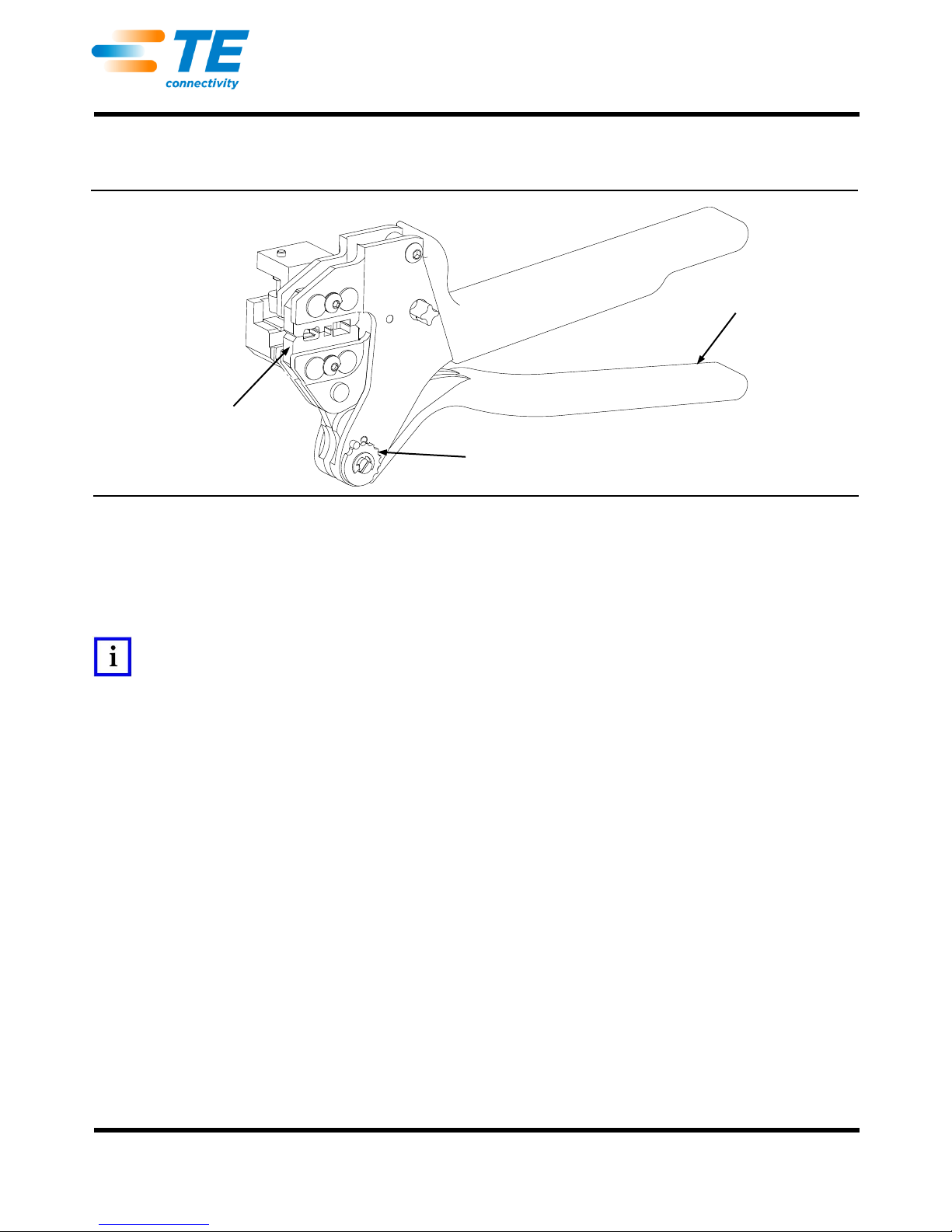
SDE PEW-12 Hand Crimping
Tool Assembly 2031734-1 with
Die Assembly 2031734-2
SDE PEW-12 Hand
Crimping Tool 2031734-1
Die Assembly
2031734-2
Hand Tool Frame
Assembly 9-1478240-0
Ratchet Adjustment
Wheel
ORIGINAL
INSTRUCTIONS
Instruction Sheet
408-10243
02 JUL 15 Rev E
Figure 1
1. INTRODUCTION
This instruction sheet provides information on the application and maintenance procedures for the SDE
PEW-12 Hand Crimping Tool 2031734-1. This tool consists of Hand Tool Frame Assembly 9-1478240-0
(Instruction Sheet 408-8851), and die assembly 2031734-2. See Figure 1.
NOTE
Dimensions in this instruction sheet are in millimeters with [inches in brackets]. Figures and illustrations are for reference only
and are not drawn to scale.
2. DESCRIPTION
The die assembly is designed with two crimp nests to terminate the RJ Point Five* Plug Kit 2007312-1 utilizing
a shell crimp (scroll crimp), and a contact piercing crimp. This document only deals with the termination
procedures. Complete assembly procedures for the plug kit may be found in Application Specification
114-13235.
3. INSTALLATION AND REMOVAL OF DIE SET AND LOCATOR ASSEMBLY
1. Open the tool handles and remove the two die retaining screws from the tool jaws.
2. Place the wire anvil so that the chamfered side and the marked surfaces face outward, when mounted
in the moving jaw of the tool frame.
3. Insert the short die retaining screw through the jaw and through the anvil die, and tighten the screw
just enough to hold the die in place. Do not tighten the screw completely at this time.
4. Place the wire crimper so that the chamfered side and the marked surface face outward, when
mounted in the stationary jaw of the tool frame.
just enough to hold the die in place. Do not tighten the screw completely at this time.
6. Carefully close the tool handles, making sure that the anvil and crimper align properly. Continue
closing the tool handles until the ratchet in the tool frame has engaged sufficiently to hold the anvil and
crimper in place, then tighten both die retaining screws.
5. Insert the long die retaining screw through the jaw and through the crimper die, and tighten the screw
1 of 5
2 of 5
7. Place the nut onto the end of the long screw and tighten the nut enough to hold the locator assembly
Stripped Cable Jacket
9.50 ±0.25
[.374 ±.010]
in place, while still allowing the locator to slide up and down.
8. To disassemble, close the tool handles until the ratchet releases, remove the nut, the locator
assembly, the two die retaining screws, and slide the anvil and crimper out of the tool jaws.
NOTE
The ratchet has detents with audible “clicks” as the handles are closed. The ratchet releases on the sixth “click”.
Figure 2
4. CRIMPING PROCEDURES
NOTE
Prior to stripping the cable, make sure to slide the strain relief and shell onto the cable and away from the stripping area. See
Figure 2.
408-10243
NOTE
This tool is provided with a crimp adjustment feature. Initially, the crimp height should be verified as specified in Figure 7.
Refer to Section 5, Crimp Height Inspection, and Section 6, crimp height Adjustment, to verify crimp height before using the
tool to crimp desired contacts and wire sizes.
1. Strip the cable jacket to 9.50 ±0.25 mm [.374 ±.010 in.] as shown in Figure 2.
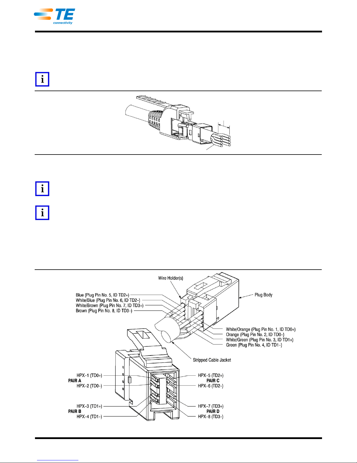
2. Insert the discrete wires into the wire holders according to the wiring diagram provided in Figure 3 until
bottomed. After wire insertion, the holders shall be sandwiched on the plug body prior to crimping. See
Figure 3.
Rev E
Figure 3

408-10243
3 of 5
Assembly Located
in Lower Jaw
Wire Side
Piercing of Contacts
Shell Seam
Shell
Terminated
Assembly
Assembly Located
in Upper Jaw
Crimp Shell
Terminated
3. Hold the tool so that the back (wire side) is facing you. Squeeze tool handles together and allow them
to open fully.
NOTE
Make sure the wires are bottomed in their respective wire slots prior to the crimping procedure.
4. Insert the assembly into the lower jaw of the hand tool. Locate the module and crimp. See Figure 4.
Figure 4
5. After termination, slide the shell over the module assembly and bottom. In order to ensure that the
shell is oriented properly for placement in the crimping tool, make sure the shell seam is opposite the
plug latch prior to insertion of the plug body. See Figure 5.
6. Insert assembly into the jaw of the hand tool and crimp.
NOTE
Make sure the cable jacket is located under the crimp area of the shell. See Figure 6.
Rev E
Figure 5
Figure 6

4 of 5
7. Complete the assembly procedures according to the information provided in Application Specification
WIRE SIZE
CRIMP HEIGHT DIMENSION
WIRE PIERCING
SCROLL CRIMP
See Figure 3
5.80 ±0.10 [.228 ±.004]
4.75 ±0.13 [.187±.005]
Adjustment Screw
Ratchet
Adjustment Wheel
114-13235.
5. CRIMP HEIGHT INSPECTION
Proceed as follows:
1. Refer to Section 4, CRIMPING PROCEDURE, and crimp the contact(s) accordingly.
2. Measure the wire barrel crimp height listed in Figure 7. If the crimp height conforms to that shown in
the table, the tool is considered dimensionally correct. If not, the tool must be adjusted. Refer to
Section 6, CRIMP HEIGHT ADJUSTMENT.
Figure 7
CAUTION
Damaged product should not be used. If a damaged contact is evident, it should be replaced. Contacts must not be reterminated.
6. CRIMP HEIGHT ADJUSTMENT
408-10243
Although the ratchet is preset prior to shipment, it is important to verify the crimp height using a micrometer or
caliper. General use and subsequent wear may cause the tool to go out of adjustment. It is recommended that
crimp height be inspected, and the ratchet be adjusted, if necessary, on a regular basis. Refer to Figure 8, and
proceed as follows:
Figure 8
1. If the crimp height is larger than recommended, remove the ratchet wheel adjustment screw and
rotate the adjustment wheel counterclockwise (+) to a higher setting. Reinstall the screw. Repeat as
required.
2. If the crimp height is smaller than recommended, remove the ratchet wheel adjustment screw and
rotate the adjustment wheel clockwise (-) to a lower setting. Reinstall the screw. Repeat as required.
3. If the crimp cannot be made to conform to the recommended crimp height, the tool or die set must be
replaced. See Section 9, REPLACEMENT.
7. MAINTENANCE AND INSPECTION
7.1. Daily Maintenance
1. Remove dust, moisture, and other contaminants with a clean, soft brush, or a clean, soft, lint-free
cloth. DO NOT use any objects that could damage the dies or tool.
2. Make sure that the proper die retaining screws are properly secured.
Rev E

408-10243
5 of 5
3. When the tool is not in use, keep the handles closed to prevent objects from becoming lodged in the
dies. Store the tool in a clean, dry area.
4. Remove all lubrication and accumulated film from the dies by immersing the dies in a suitable
commercial degreaser.
7.2. Inspection
Close the tool handles until the ratchet releases, and then allow them to quickly open freely. If they do not open
quickly and fully, the spring is defective. See Section 9, REPLACEMENT.
8. REPLACEMENT
Order replacements through your TE Connectivity Representative, or call 1-800-526-5142, or send a facsimile
of your purchase order to 717-986-7605, or write to:
CUSTOMER SERVICE (038-035)
TYCO ELECTRONICS CORPORATION
PO BOX 3608
HARRISBURG PA 17105-3608
9. REVISION SUMMARY
Updated document to corporate requirements
Changed dimension in table in Figure 7
Rev E
 Loading...