

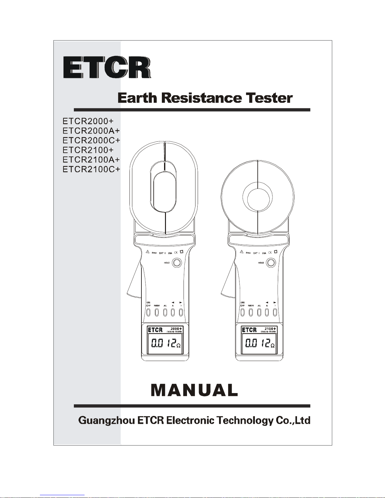
ETCR ETCR2000+, ETCR2000A+, ETCR2100A+, ETCR2100C+, ETCR2000C+ User Manual
...

CONTENT
I. Attention ....................................................................................... 1
II. Brief Introduction ........................................................................ 3
III. Specification .............................................................................. 5
1.Model of Series .................................................................. 5
2. Ranges and Accuracy of Measurement .............................. 5
3. Specifications ...................................................................... 6
IV. Structure of Meter ...................................................................... 7
V. Liquid Crystal Display ................................................................. 8
1. LCD Screen ......................................................................... 8
2. Description of Special Symbols........................................... 9
3. Examples Illustrated .......................................................... 10
VI. Operating Method ....................................................................11
1.Boot up ................................................................................11
2.Shutdown ......................................................................... 12
3.Resistance Measurement ................................................ 13
*4.Current Measurement .................................................... 14
5.Date Lock/Release/Storage............................................. 15
6.Data Access ..................................................................... 16
7.Alarm Settings ................................................................. 16
8.Access to Alarm Critical Value ......................................... 17
9.Clear Data........................................................................ 17
VII. Measurement Principle .......................................................... 18
1. Principle of Resistance Measurement .............................. 18
2. Principle of Current Measurement .................................... 18
VIII. Measurement Method of Earth Resistance .......................... 19

1. Multi-Point Grounding System ............................................ 19
2. Limited Point Grounding System ........................................ 20
3. Single-Point Grounding System.......................................... 21
IX. Bill of Loading .......................................................................... 24
X. Parts List and Assembly Details............................................... 25
1. Parts List ........................................................................... 25
2. Assembly Details ............................................................... 26
XI.Trouble shooting ...................................................................... 27

-1-
I. Attention
Thank you for purchasing this pincers earth tester from ETCR
Electronic Technology Company. In order to make better use of the
product, please be certain:
----To read this user manual carefully.
----To comply with the operating cautions presented in
this manual.
1 Under any circumstances, use the Meter should pay special
attention to safety.
2 Pay attention to the measurement range of the Meter and the
using environment provided.
3 Pay attention to the text labeled on the panel and back plane
of the Meter.
4 Before booting up, the trigger should be pressed for 1-2 times
to ensure the jaws are well closed.
5 At Boot time, DO NOT press the trigger, nor clamp any wire.
6 Before the auto inspection is completed and the "OL Ω"
symbols are showed, the measured objects cannot be
clamped on.
7 The jaw planes contact must be maintained clean, and should
not be polished with corrosive and rough materials.
8 Avoid any impact onto this Meter, especially the Jaw contact
surface.
9 This Meter will have some buzzing sound in measurement

-2-
process, and it is normal.
10 The measurement current of the wire should not exceed the
upper limit of the Meter.
11 Please take out the batteries in the case of the Meter being
idle for a long time.
12 The dismantling, calibration and maintenance the Meter shall
be operated by the authorized staff.
13 If the continuing use of it would be dangerous, the Meter
should be stopped using immediately, and immediately sealed
for the treatment by the authorized agencies.
14 The contents in this user manual marked with "*" are limited to
C+.

-3-
II. Brief Introduction
This instrument was designed by technical department of
ETCR Electronic Technology Company. Its performance is mainly
reflected in:
u Breakthrough in self-test the boot a long time to wait, start
immediately into the test.
u Breakthrough relay self-test mode, using the most
advanced processing algorithms and digital integration
technology, a fully intelligent.
u Break the old product to heavy issues, more in line with
characteristics of handheld devices.
u New design, panel operation with 6 buttons, better
performance.
u An increase of sound and light alarm, "beep—beep--beep
--" alarm sound.
u Increase the interference signal recognition indicator.
u Improved anti-jamming capability and test stability.
u Stored data: 99 Units.
u Wider range: 0.01Ω-1200Ω
u Lower power consumption: Maximum operating current
not exceeding 50mA.
ETCR series of Pincers Earth Tester is widely used in the
grounding resistance measurement of the power,
telecommunications, meteorology, oilfield, construction and the
-4-
industrial and electrical equipment.
ETCR series of Pincers Earth Tester, in the measurement of a
grounding system with loop current, does not require breaking
down the grounding wire, and need no auxiliary electrode. It is safe,
fast and simple in use.
ETCR series of Pincers Earth Tester can measure out the
faults beyond the reach of the traditional methods, and can be
applied in the occasions not in the range of the traditional methods.
ETCR series of Pincers Earth Tester can measure the
integrated value of the grounding body resistance and the
grounding lead resistance.
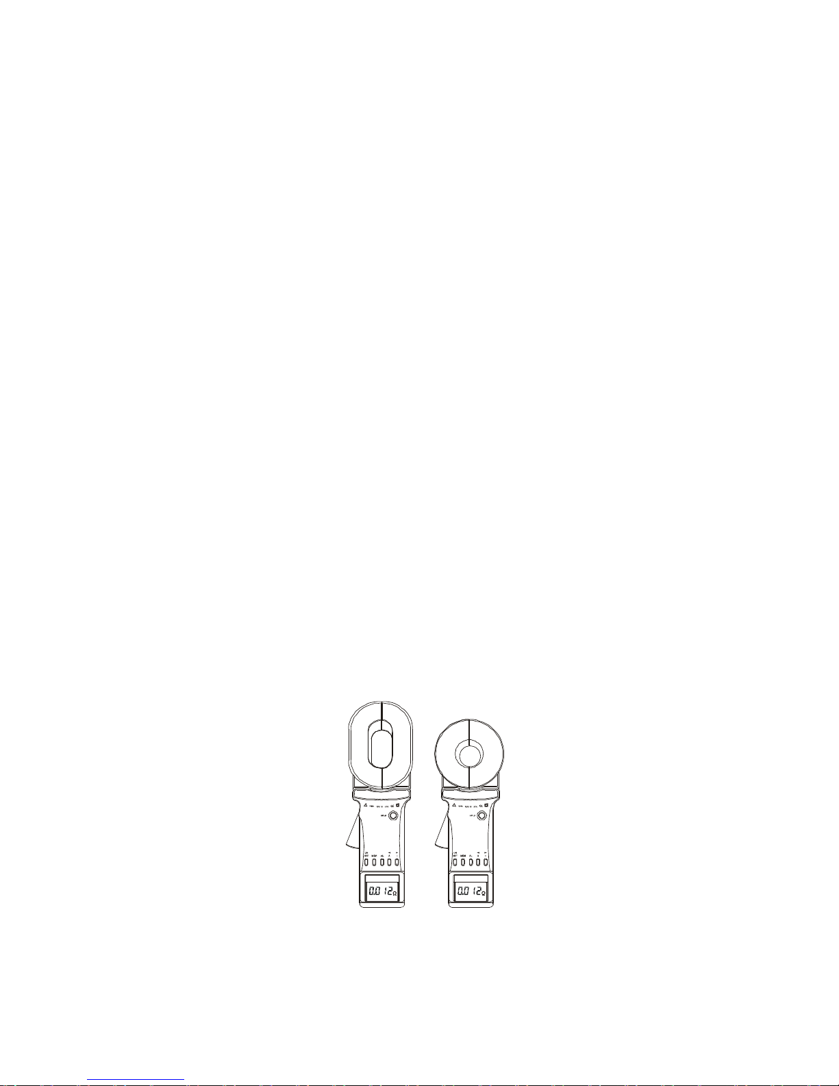
ETCR series of Pincers Earth Tester is equipped with a long
jaw, as indicated in the figure below. A long jaw is particularly
suitable for the occasion of grounding with the flat steel.
In addition,
C+ Pincers Earth Tester is also able to measure the leakage
current and the neutral current in the grounding system.
-5-
III. Specification
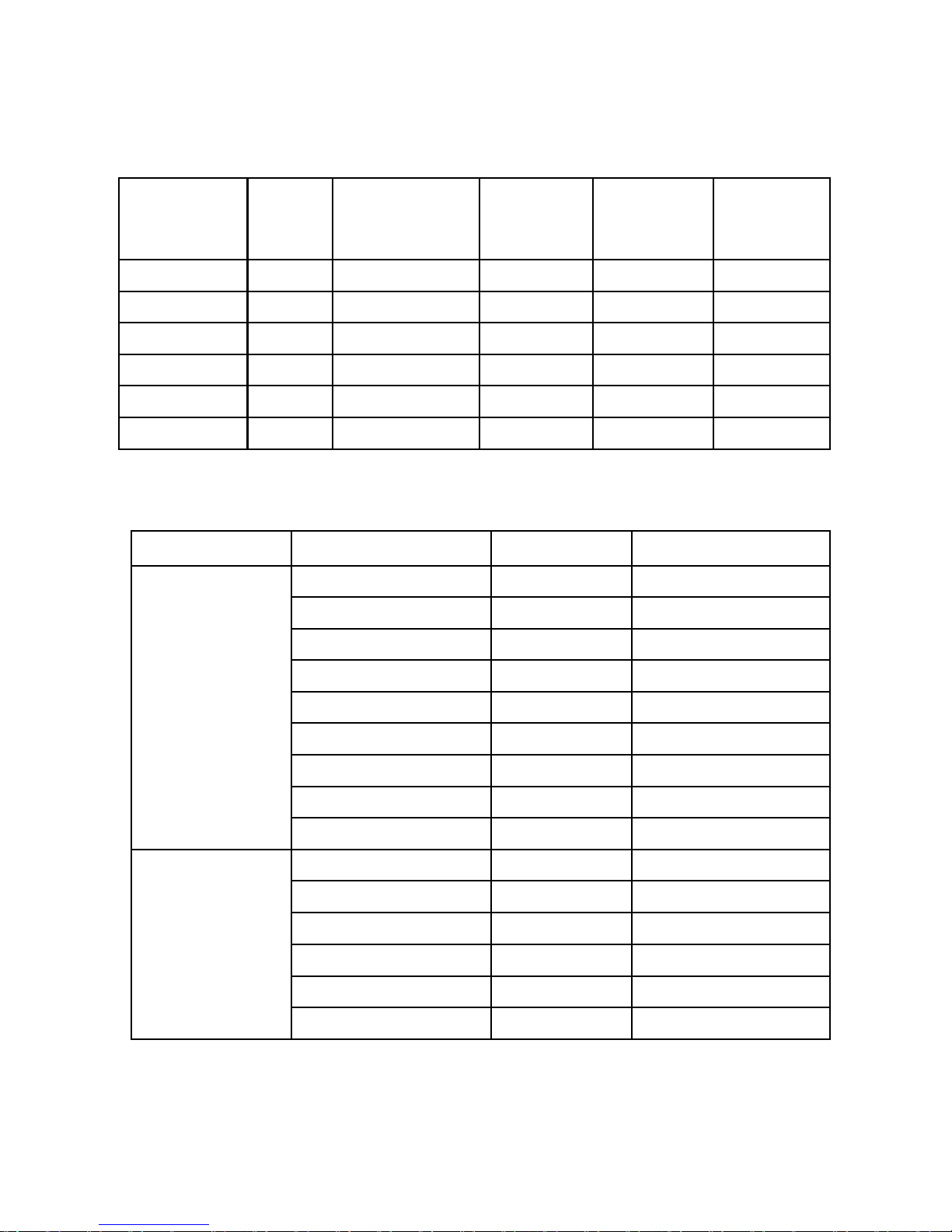
1. Model of Series
Model
Jaw
Size
(mm)
Range of
Resistance
(Ω)
Range of
Current
(A)
Storage
Function
Alarm
Function
ETCR2000+ 65×32
0.01--1200 -- 99 Units
√
ETCR2000A+
65×32
0.01--200 -- 99 Units
√
ETCR2000C+
65×32
0.01--1200 0.0--20.0 99 Units
√
ETCR2100+ φ32 0.01--1200 -- 99 Units
√
ETCR2100A+
φ32 0.01--200 -- 99 Units
√
ETCR2100C+
φ32 0.01--1200 0.0--20.0 99 Units
√
Note: “√” means available.
2. Ranges and Accuracy of Measurement
Mode Range Resolution
Accuracy
Resistance
0.010Ω-0.099Ω 0.001Ω ±(1%+0.01Ω)
0.10Ω-0.99Ω 0.01Ω ±(1%+0.01Ω)
1.0Ω-49.9Ω 0.1Ω ±(1%+0.1Ω)
50.0Ω-99.5Ω 0.5Ω ±(1.5%+0.5Ω)
100Ω-199Ω 1Ω ±(2%+1Ω)
200Ω-395Ω 5Ω ±(5%+5Ω)
400-590Ω 10Ω ±(10%+10Ω)
600Ω-880Ω 20Ω ±(20%+20Ω)
900Ω-1200Ω 30Ω ±(25%+30Ω)
*Current
(True-RMS)
0.00mA -9.00mA 0.05mA ±(2.5%+2mA)
10.0mA -99.0mA 0.1mA ±(2.5%+10mA)
100mA -300mA 1mA ±(2.5%+20mA)
0.30A-2.99A 0.01A ±(2.5%+0.1A)
3.0A-9.9A 0.1A ±(2.5%+0.5A)
10.0A-20.0A 0.1 A ±(2.5%+1 A)
Resistance Measurement Frequency: >1KHz
Measured Current Frequency: 50Hz/60Hz
Setting Range of Resistance Alarm Critical Value: 1Ω-199Ω
*Setting Range of Current Alarm Critical Value:1mA -499mA

-6-
3. Specifications
Instrument safety: IEC/EN61010-1, IEC/EN6010-2-032
Insulation: double insulation
Pollution degree: class II
Overvoltage category: CAT III 150V to ground, Max 20A
Degrees of protection:
-IP30, Group III equipment as per EN 60529 Ed 92
-IK04, as per EN 50102 Ed 95
Dimensions(L×W×H):
-Long elliptic jaw: 285mm×90mm×66mm; (11×4×3 inches)
-Round jaw: 260mm×90mm×66mm;(10×4×3 inches)
Span of Jaw: Long elliptic jaw 35mm; round jaw 32mm
Weight (including batteries): Long elliptic jaw-1160g, Round
jaw-1120g
Battery type: 4 ×1.5V alkaline LR6 AA battery
Low battery indication: is displayed
Internal consumption: <50mA
Auto Power off: after 5 minutes of idleness
Display: 4 LCD, sign, decimal point and backlight
Memory size: 99 Units of Reading
Environment (Temperature & Relative Humidity):
-Working: -10°C~55°C, 10%RH-90%RH
-Storage: -20°C ~60°C, below 70%RH
Range shift: Full range automatic shifting
External magnetic field: <40A/m
External electric field: <1V/m
Data upload interface: RS232 (Optional)
-7-
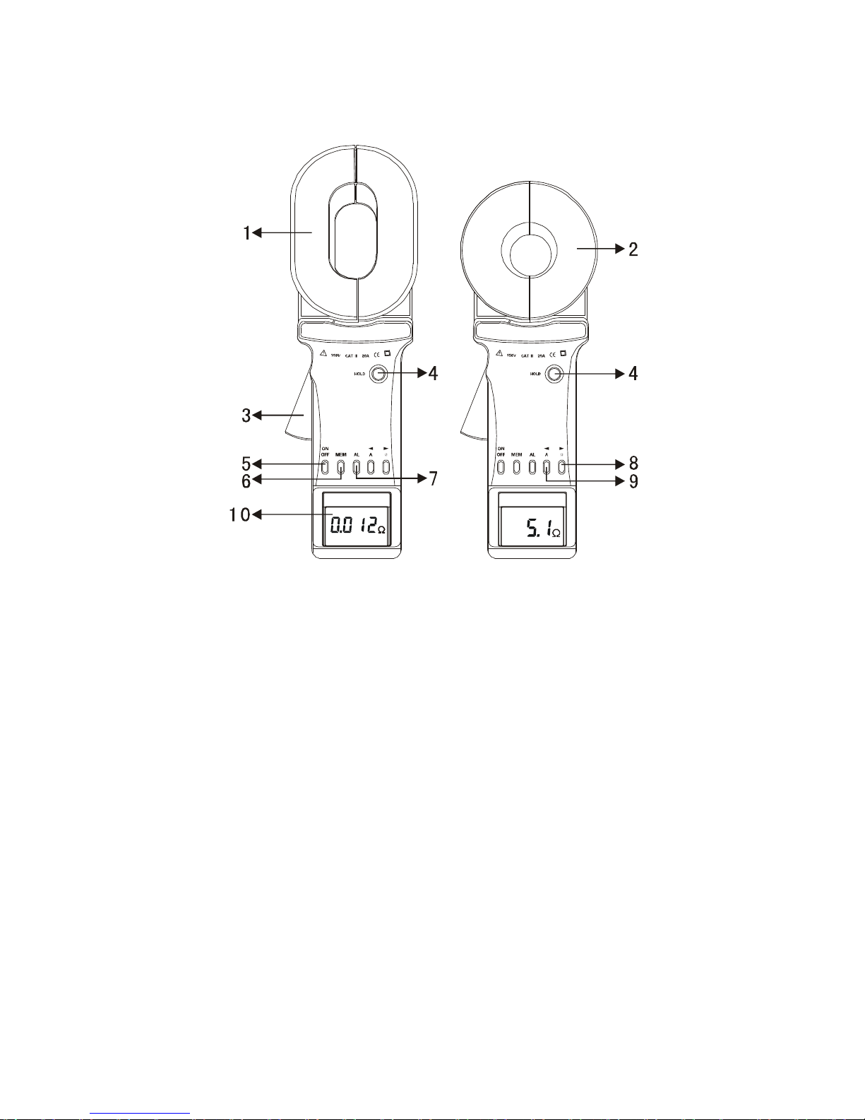
IV. Structure of Meter
1. Long Pincers Jaw : 65mmx32mm
2. Round Pincer Jaw : φ32mm
3. Trigger: to control opening and closing of jaw
4. HOLD Key: lock / Release display / Storage
5. POWER Key: Boot Up / Shutdown /*Quit /Clear Data
6. MEM Key: Data Access / Clear Data
7. AL Alarm Function Key: Alarm Open / Turn Off / Alarm Critical
Value Setting
8. Resistance Measure Switch Key Ω (Right Arrow Key)
9. *Current Measure Switch Key A (Left Arrow Key)
10. Liquid Crystal Display (LCD)
Note: "*" is limited to C+.
 Loading...