

ETCR 7300, 7300A User Manual


CONTENT
Warning ....................................................................................................1
Ⅰ.Introduction.........................................................................................2
Ⅱ. Model .................................................................................................3
Ⅲ. Electrical Symbols ............................................................................3
Ⅳ. Technical Specification ....................................................................3
Ⅴ. Measurement Accuracy ...................................................................5
1.Base Conditions and Working Conditions ..................................5
2.AC Voltage U ..............................................................................6
3.AC Current I ...............................................................................6
4.Frequency F ................................................................................6
5.Active Power P: W=( V×A×COSФ) ...........................................6
6.Apparent Power S: VA=( V×A) ..................................................7
7.Reactive Power Q: VAR=( V×A×sinФ) ......................................7
8.Power Factor PF: PF=W/ VA ......................................................7
9.Phase Angle .................................................................................7
10.Power Energy W .......................................................................8
Ⅵ. Instrument Structure ........................................................................8
Ⅶ. Method of Operation ......................................................................10
1.Switch On/Off ...........................................................................10
2.Choose measurement mode ......................................................10
3.Max and Min measurement .......................................................10
4.Backlight Control ......................................................................10
5.Data Hold/Storage .....................................................................10
6.Data Access/ Exit ...................................................................... 11
8.Delete Data ................................................................................ 11
9.Measurement Instruction ........................................................... 11
Ⅶ. Battery Replacement .....................................................................22
Ⅷ. Accessories .....................................................................................22

Warning
Thank you for purchasing our ETCR7300 Series Large Caliber Three Phase
Power Tester, in order to better use of this product, be sure to:
----To read this user manual carefully.
----Comply strictly with safety rules and precautions set out in this manual.
u Pay special attention to safety under any circumstances while using the
instrument.
u Take note of the label text and symbols on the panel and back of the
instrument.
u Keep the clamp clean and maintain regularly.
u Please don’t connect the tester with computer via RS232 during voltage
measurement.
u Please don’t place and store the instrument at the place with high
temperature, humidity, moisture condensation and straight sunlight for a
long time.
u Replace battery in time when the battery voltage is low.
u Remove or replace the battery if you expect not to use the instrument for a
long time.
u Take note of the polarity when replace the battery.
u The operation, demolition, calibration and maintenance of the instrument
must be carried out by qualified personnel authorized to do so.
u The meter should be stopped from being used immediately and sealed if
danger is brought up in case of continued use; only a competent body can
be authorized to deal with it.
u “ ” in the manual is the safety warning sign, the contents of this manual
must be followed for safe operation.
u “ ” and other safety signs, the contents of this manual must be followed
for safe operation.
-1-

Ⅰ.Introduction
ETCR7300 Series Large Caliber Three Phase Power Tester is well
designed and manufactured for measuring three phase AC voltage, current,
leakage current, phase between current and voltage, phase between phase
voltage, frequency, power energy, phase sequence, active power, reactive
power, apparent power, power. It is a multifunctional, digital, intelligent tester.
Its large caliber 80mm×80mm can clamp electric cable of 80mm diameter, or
96mm×4mm flat cable and steel earth wires. It has all the functions of Large
Caliber Leakage Clamp Meter and Micro Power Clamp Meter. Besides, it also
has this functions such as distinguish transformer wiring group, inductive and
capacitive circuits, test second circuit and bus differential protection systems,
read the phase relationship between CTs of the differential protection, check
the meter wiring right, repair lines and equipment, etc. Provide operators with
a safe, accurate and convenient tester.
ETCR7300 Series Large Caliber Three Phase Power Tester’s clamp
core is made of special alloy, adopt the latest magnetic shielding techniques,
can almost shield the influence from external magnetic field, to ensure the
high precision, high stability and high reliability of perennial uninterrupted
measurement. The meter can store 200 sets of data, with RS232 interface,
upload stored data to the computer through the system software,
implementing online real-time monitoring, historical inquires, dynamic display.
With the function of historical data read, preserve, print, and backlight, data
hold, etc. It is a necessary tool for electrical safety testing.
-2-
Ⅱ. Model
Model Measurement Range Resolution
ETCR
7300
ETCR
7300A
Note: Other function is the same.
AC0.00mA-1200A
AC 0.5W-720KW
AC 0.0A-2000A 0.1A
AC 0.1K-1200KW
0.01mA
0.01W
1W
Can measure leakage
Can measure big current,
measure leakage current
Note
current, low power
high power. Can’t
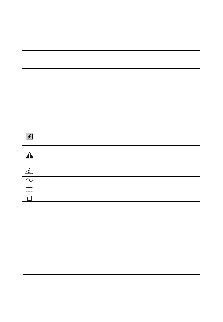
Ⅲ. Electrical Symbols
Extremely dangerous! The operator must strictly abide by the safety
rules; otherwise there is risk of electric shock, resulting in bodily
injury or fatalities.
Dangerous! The operator must strictly abide by safety rules;
otherwise there is risk of electric shock, resulting in bodily injury or
fatalities.
Warning! Safety rules must be strictly abided by, otherwise personal
injury or equipment damage may be caused.
Alternate Current(AC)
Direct Current(DC)
Double Insulation
Ⅳ. Technical Specification
Measure three phase AC voltage, leakage current,
current, active power, reactive power, apparent
Function
Power
Test Mode Clamp CT, integral mode
Clamp Size
-3-
power, power, phase between current and voltage,
phase between phase voltage, frequency, power
energy, phase sequence
6V DC(LR6×4 alkaline dry batteries, continuously
working for 12 hours)
80mm×80mm(can clamp electric cable of 80mm
diameter, or 96mm×4mm flat cable and steel earth
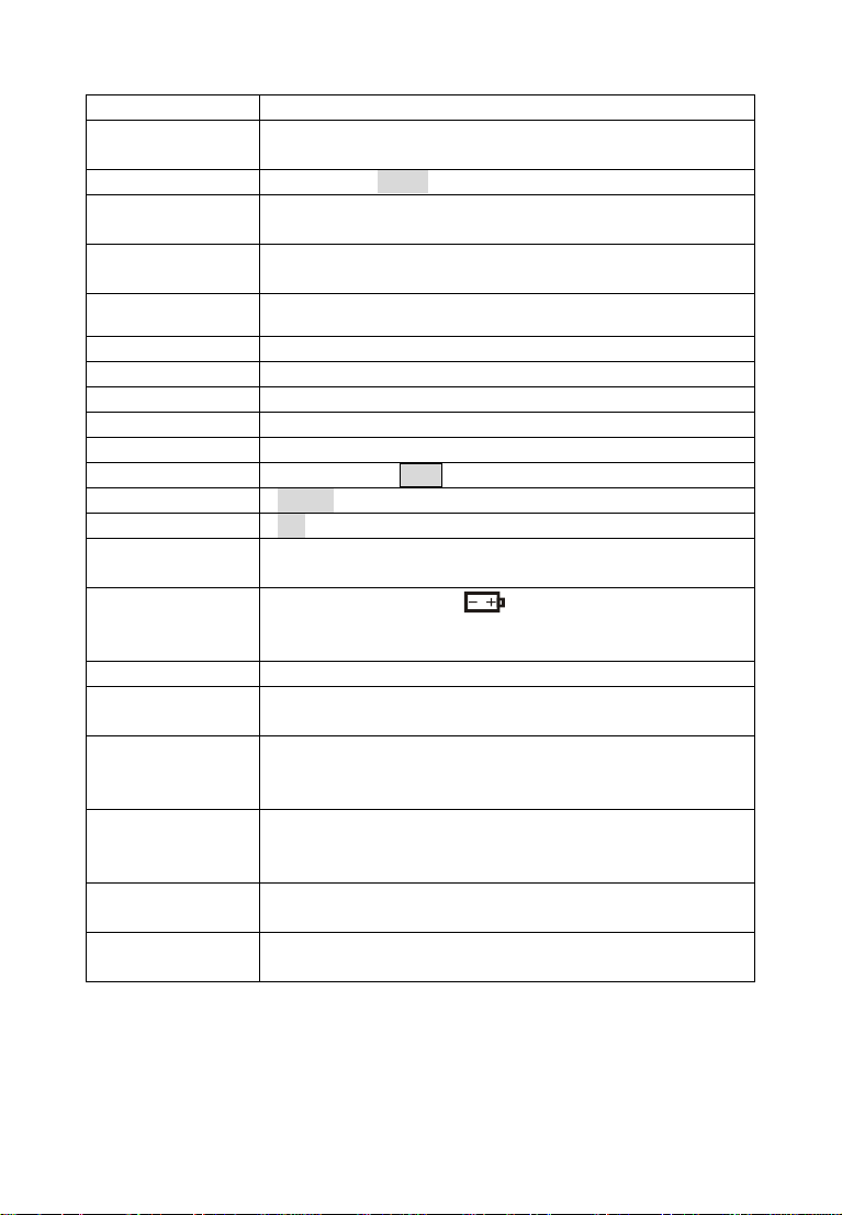
wires)
*
Measured Wire
Position
Data Storage 200 sets, “FULL” symbol indicate the memory is full
RS232 Interface
Communication
Wire
Frequency
Gear Shift Automatic shift
Sample Rate About 2 times/second
Line Voltage Below AC 600V line measurement
Display Mode LCD: 128dots×64dots; Display area: 43mm×29mm
Meter Size Length 275mm × Width 145mm × Height 40mm
Backlight Controlled by “
Data Hold “HOLD” symbol appears
Overflow “OL” symbol appears
Automatic
Shutdown
Voltage
Detection
Weight 1kg(with batteries and accessories)
Working
Current
Working
Temperature
and Humidity
Storage
Temperature
and Humidity
Insulation
strength
Safety
Specifications
Measured wire at approximately the geometric center
of the clamp
With RS232 interface, download data to computer for
analysis and management
RS232 communication wire, 1.8m
50Hz ,60Hz automatic identification
”key
Automatically shutdown about 15 minutes after power
on to reduce battery consumption
Low battery symbol “ " appears to remind the
replacement of battery when the battery voltage drops
below 5.2V.
50mA with enabled backlight; 25mA with disabled
backlight
-10℃-40℃; 80%rh
-10℃-60℃; below 70%rh
AC 3700V/rms(between core and shell)
IEC1010-1, IEC1010-2-032, 2 class of pollution, CAT
Ⅲ(600V)
-4-

Ⅴ. Measurement Accuracy
1.Base Conditions and Working Conditions
Influence Quantity Model
Ambient Temp
Ambient Humidity
Signal Waveform
Signal Frequency
Current Amplitude
in Power/Power
Energy/Phase/Phase
Sequence Test
Current Amplitude
in Power/Power
Energy/Phase/Phase
Sequence Test
Voltage Amplitude in
Power/Power
Energy/Phase/Phase
Sequence Test
Current Amplitude
in Power Factor Test
Current Amplitude
in Power Factor Test
Voltage Amplitude in
Power Factor Test
External Electric
Magnetic Field
Measured Wire
Position
7300
7300A
7300
7300A
7300
7300A
7300
7300A
7300 5A±0.1A 50mA-1200A
7300A
7300
7300A
7300 5A±0.1A 50mA-1200A
7300A
7300
7300A
7300
7300A
7300
7300A
Base
Condition
23℃±1℃ -10℃-40℃ ----
40%-60% <80% ----
sine wave sine wave
50HZ±1HZ 45HZ-65HZ ----
50A±1A 10A-2000A ----
50V±1V 10V-600V ----
50A±1A 10A-2000A
100V±20V 10V-600V ----
To be avoided
Measured wire at approximately the
geometric center of the clamp
Working
Condition
Note
β
=0.01
----
Power
factor:
0.3-1
Power
factor:
0.3-1
-5-

2.AC Voltage U
Measurement Range
0.00V-9.99V
10.0V-99.9V 0.1V
100V-600V 1V
Accuracy Resolution
7300 7300A 7300 7300A
0.01V
±(1.5%+5dgt)
3.AC Current I
Measurement
Range
0.00mA-9.99mA ±(1.5%+5dgt)
10.0mA-99.9mA ±(1.5%+5dgt)
100mA-999mA ±(1.5%+5dgt) ±(2.0%+5dgt)
1.00A-9.99A ±(1.5%+5dgt) ±(2.0%+5dgt) 0.01A 0.1A
10.0A-99.9A ±(1.5%+5dgt) ±(2.0%+5dgt)
100A-1199A ±(2.0%+5dgt) ±(2.0%+5dgt)
1200A-2000A ---- ±(2.5%+5dgt)
Accuracy Resolution
7300 7300A 7300 7300A
---- 0.01mA
---- 0.1mA ---1mA 0.1A
0.1A 0.1A
1A 1A
---- 1A
----
4.Frequency F
Measurement
Range
Accuracy Resolution
7300 7300A 7300 7300A
25Hz-100Hz ±(0.5%+5dgt) 0.1Hz
5.Active Power P: W=( V×A×COSФ)
Measurement
Range
0.50W-9.99W ±(3%+5dgt) ---- 0.01W ----
10.0W-99.9W ±(3%+5dgt) ---- 0.1W ----
0.10KW-9.99KW
10.0KW-99.9KW
-6-
±(3%+5dgt) ±(3%+5dgt) 0.01KW 0.01KW
±(3%+5dgt) ±(3%+5dgt) 0.1KW 0.1KW
Accuracy Resolution
7300 7300A 7300 7300A
 Loading...