

Page 1
Page 2

CONTENT
I. Safety Precautions And Procedures ................................................ 1
1. Preliminary Instructions ................................................................ 2
2. During Use .................................................................................... 2
3. After Use ....................................................................................... 3
II. Introduction ......................................................................................... 3
III. Model .................................................................................................. 4
IV. Electrical Symbols ............................................................................ 4
V. Technical Specification ...................................................................... 4
VI. Instrument Structure......................................................................... 6
VII. LCD Display ..................................................................................... 7
VIII. Method of Operation ...................................................................... 7
1. Switch On/Off ........................................................................... 7
2. Data Hold/Storage ...................................................................... 7
3. Data Access/ Exit ....................................................................... 8
4. Data Upload ............................................................................... 8
5. Delete Data................................................................................. 8
6. General Measurement ................................................................ 8
7 . PEAK Measurement ............................................................... 10
IX. Battery Replacement ..................................................................... 10
XI. Accessories ..................................................................................... 11
Page 3
I. Safety Precautions And Procedures
This instrument was designed in compliance with IEC1010-1& IEC1010-2-032
safety guideline relative to electronic equipment.
For your own safety and to avoid damaging the instrument you are
recommended to follow the procedures described in this manual and read
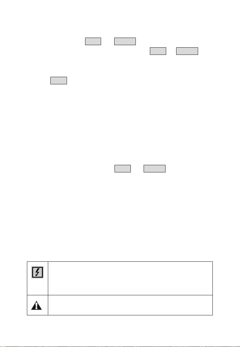
carefully all instructions preceded by this symbol
Before and during measurements keep to the following instructions:
● Do not take current measurements in wet places
● Do not take the measurements in the presence of explosive gas and
combustibles or in dusty places
● Avoid any contact with the circuit under test even though you are not
taking any measurement
● Avoid any contact with exposed metal parts, unused measuring terminals,
circuits etc. Do not take any measurement whenever anomalous conditions
occur such as deformations, breaks, leakages, blind display etc
The herewith symbols are used in this manual and on the meter
CAUTION: refer to the instruction manual. An improper use may
damage the instrument or its components as well as endanger the user.
High voltage danger: risk of electric shock
-1-
Page 4
1. Preliminary Instructions
● This instrument has been designer for use in environments with pollution
degree 2
● It can be used for voltage and current measurements on electrical
installations with overvoltage CAT III 600V
● You are recommended to respect the usual safety regulations aimed at
protecting you against dangerous current and protecting the instrument
against improper use
● Only the original accessories supplied along with the instrument guarantee
compliance with the safety standards in force. They must be in a good
conditions and, if necessary, replaced with identical ones
● Do not test nor connect to any circuit exceeding the specified overload
protection
● Do not take measurements under environmental conditions exceeding the
limits indicated in this manual
● Make sure that batteries are correctly installed
2. During Use
You are recommended to read carefully the following instructions:
CAUTION
Failure to comply with warnings and instructions may damage the
instrument and/or its components as well as injure the operator
● Do not measure in the presence of external voltages. Although the
instrument is protected, an excessive voltage may cause malfunction
● Avoid submitting the instrument to voltage while measuring (i.e. a test lead
slipping off the measuring point accidentally touching an energized point)
-2-
Page 5
CAUTION
If the “low battery” symbol is displayed during use
interrupt testing, switch off the instrument and replace batteries.
u (Take note of the polarity when replace the battery.)
3. After Use
● Turn off the instrument pressing ON/OFF key after using it
● If you expect not to use the instrument for a long time remove batteries
II. Introduction
ETCR7100 series of Super-large Caliber Leakage Clamp Meter is well
designed and manufactured for measuring AC leakage current, current,
voltage, adopt the latest CT technology and digital integrated technology. Its
large caliber 108mm×148mm can clamp electric cable of 108mm diameter, or
160mm×4mm flat cable and steel earth wires. It is suitable for leakage current
measurement of cable and transformer earth steel. Full automatically and
LCD display, all the data are displayed in the screen, which is very clear and
convenient. The meter is widely used in electric power, communication,
meteorology, railway, oil field, architecture, measuring, teaching research unit,
industrial mining enterprises, etc.
ETCR7100 series of Super-large Caliber Leakage Clamp Meter’s
clamp core is made of special alloy, adopt the latest magnetic shielding
techniques, to ensure the high precision, high stability and high reliability of
perennial uninterrupted measurement. The meter can store 99 sets of data,
with RS232 interface, upload stored data to the computer through the system
software, implementing online real-time monitoring, historical inquires,
-3-
Page 6
dynamic display. With the function of historical data read, preserve, print, and
backlight, data hold, etc. It is a necessary tool for electrical safety testing.
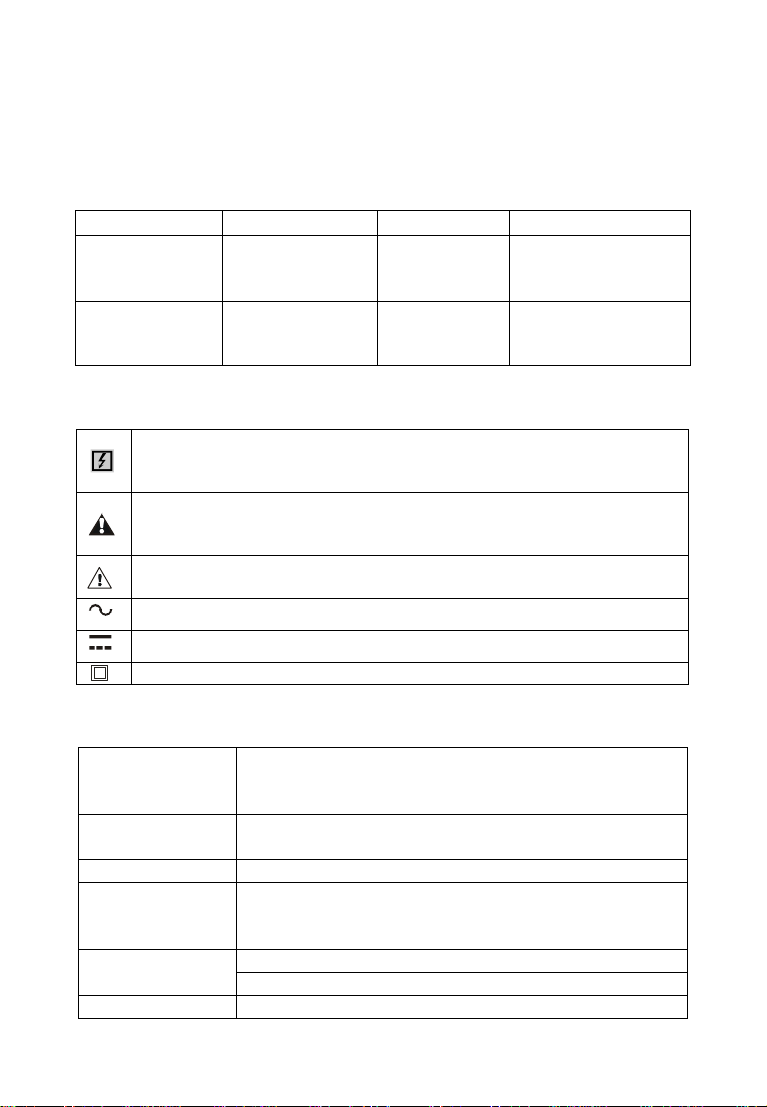
III. Model
Model Range (AC) Resolution Note
ETCR 7100 0.0mA- 3200A 0.1mA
Measure leakage
current
ETCR 7100A 0.0A- 4000A 0.1A
Measure big
current
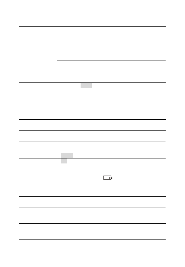
IV. Electrical Symbols
Extremely dangerous! The operator must strictly abide by the safety
rules; otherwise there is risk of electric shock, resulting in bodily
injury or fatalities.
Dangerous! The operator must strictly abide by safety rules;
otherwise there is risk of electric shock, resulting in bodily injury or
fatalities.
Warning! Safety rules must be strictly abided by, otherwise personal
injury or equipment damage may be caused.
Alternate Current(AC)
Direct Current(DC)
Double Insulation
V. Technical Specification
Measure AC leakage current, big current (particularly
Function
Power
Test Mode Clamp CT, integral mode
Clamp Size
Measurement
Range(AC)
Resolution(AC) ETCR7100: 0.1mA
suitable for leakage current measurement of cable
and transformer earth steel)
6V DC(LR6×4 alkaline dry batteries, continuously
working for 12 hours)
108mm×148mm (can clamp electric cable of 108mm
diameter, or 160mm×4mm flat cable and steel earth
wires)
ETCR7100: 0.0mA~3200A
ETCR7100A: 0.A~4000A
-4-
Page 7
ETCR7100A: 0.1A
Measurement
0.0mA~499A ±2%±5dgt
Accuracy(AC)
(23°C±3°C,
500A~999A ±3%±5dgt
below 70%RH,
measured wire
1000A~2999A ±4%±5dgt
at the center of
the clamp)
Measured Wire
Position
3000A~4000A ±5%±5dgt
Measured wire at approximately the geometric center
of the clamp
Data Storage 99 sets, “FULL” symbol indicate the memory is full
RS232 Interface
Communication
Wire
Frequency
With RS232 interface, download data to computer for
analysis and management
RS232 communication wire, 1.8m
50Hz ,60Hz automatic identification
Gear Shift Automatic shift
Sample Rate About 2 times/second
Line Voltage Below AC 600V line measurement
Display Mode 4 digital LCD display, length 47mm×width 28.5mm
Meter Size Length 350mm × Width 180mm × Height 55mm
Backlight Suitable for dim places
Data Hold “HOLD” symbol appears
Overflow “OL” symbol appears
Automatic
Shutdown
Voltage
Detection
Automatically shutdown about 5 minutes after power
on to reduce battery consumption
Low battery symbol “ " appears to remind the
replacement of battery when the battery voltage drops
below 5.2V.
Weight of Meter 1.5kg (with batteries)
Weight of
Package
3kg (with accessories)
Working
Temperature
-10°C ~ 40°C; 80%rh
and Humidity
Storage
Temperature
-10°C ~ 60°C; below 70%rh
and Humidity
Insulation AC 2kV/rms(between core and shell)
-5-
Page 8
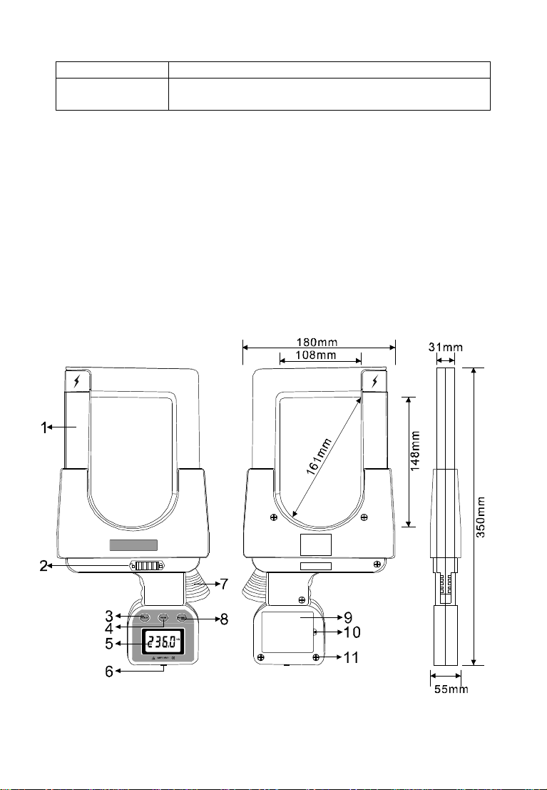
strength
Safety
Specifications
IEC1010-1, IEC1010-2-032, 2 class of pollution, CAT
III 600V
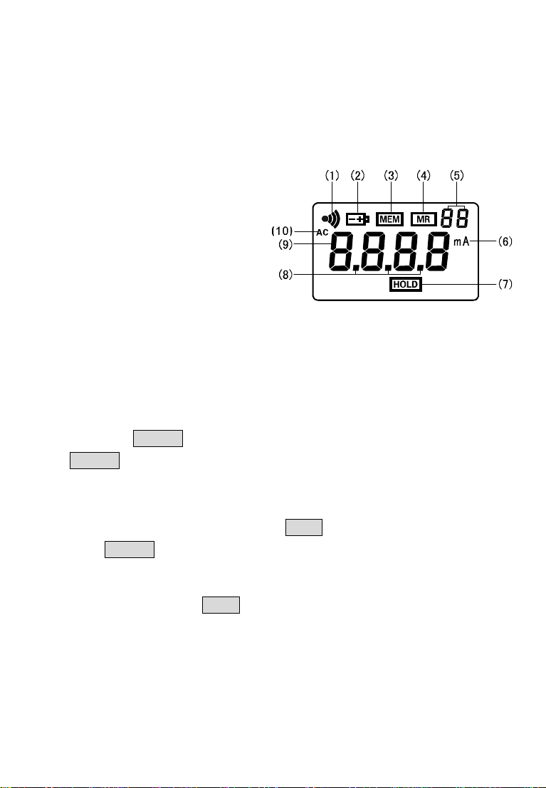
VI. Instrument Structure
1. Clamp (108mm×148mm)
2. Lock switch (after lock, the clamp can’t be open)
3. HOLD key 4. PEAK key
5. LCD display 6. RS232 interface
7. Opening lever 8. POWER key
9. Battery cover 10. Battery cover screw (1 piece)
11. Up and down cover connecting screws (6 pieces)
-6-
Page 9
VII. LCD Display
⑴. PEAK measurement mode symbol
⑵. Symbol of low battery & voltage (display when below 4.8V)
⑶. Symbol of data storage
⑷. Symbol of data access
⑸. 2-digital No. of data storage unit
⑹. Current unit (mA or A)
⑺. Data lock symbol
⑻. Metrication decimal point
⑼. 4-digital LCD figures display
⑽. Symbol of AC
VIII. Method of Operation
1. Switch On/Off
Press POWER key to switch on, LCD display, in test mode, press
POWER key to switch off. The meter will automatically power off after
booting 5 minutes later. If LCD display is darker, maybe the battery voltage
is too low, please replace batteries.
In data hold mode, firstly press HOLD key to cancel the lock, then
press POWER key to switch off.
2. Data Hold/Storage
In test mode, press HOLD key to lock currently displayed value and
display “HOLD “symbol. At the same time, this locked value as a set of data
followed by auto-ID and store, and “MEM” symbol flash one time. The meter
can store 99 sets of data. If the memory is full, display “FULL” symbol.
-7-
Page 10
3. Data Access/ Exit
Dangerous!
Ca
n not be used to test voltage higher than
In test mode, press PEAK and POWER key to access data inquiry form
group “R:01”, and display “MR” symbol. Press PEAK or POWER key to
increase or decrease the page number, it will automatically return back to
group 01 when access the last group.
Press HOLD key to exit date inquiry, back to test mode.
4. Data Upload
Connecting the meter and computer with USB-RS232 communication
line attached in package. Start up the meter, run software, choose history
access, then read, save, report, print history data, etc. The more data storage,
take the longer time to read it. Historical data can be saved in Txt text or Excel
format.
5. Delete Data
In the date inquiry mode, press PEAK and POWER key to delete all the
stored data, and return back to test mode. At the same time, “dEL” symbol
display.
6. General Measurement
During the measurement, the LCD real-time display the value of
measured current and leakage current, the value displayed on LCD change
with different current and leakage current. No measured value reserved when
take the meter away from measured wires, LCD display zero.
-8-
High voltage, very dangerous!Only qualified personnel
after training could conduct operation on it. The operator
should obey safety regulations; Otherwise there will be the
danger of electric shock resulting in personal injury or
casualty.
600V. Otherwise there will be the danger of electric shock
resulting in personal injury or casualty.
Page 11
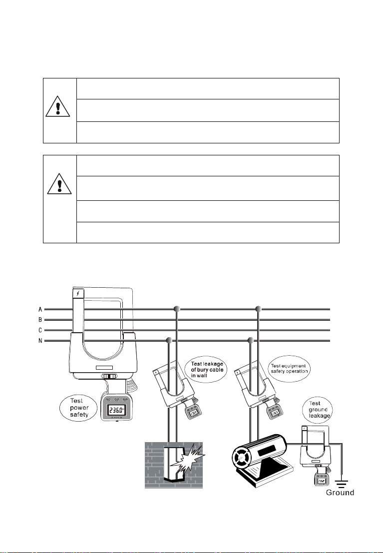
Make sure
the clamp well
closed
when measuring leakage
Clean the clamp after finishing measurement
, regularly
Clamp
live wire and null line together to measure leakage
Clamp four wires of there phase to measure the total
Clamp main
line to measure total current of that main line.
Test reference illustrations:
current and current.
Make sure the measured wire at approximately the
geometric center of the clamp.
maintain the meter.
current of electric equipment. (Note: 2 wires)
Clamp earth wire to measure grounding line leakage
current of electric equipment. (Note: single wire)
leakage current. ( Note: 4 wires)
(Note: single wire)
-9-
Page 12
In HOLD mode, press HOLD key to return back test mode. In data access
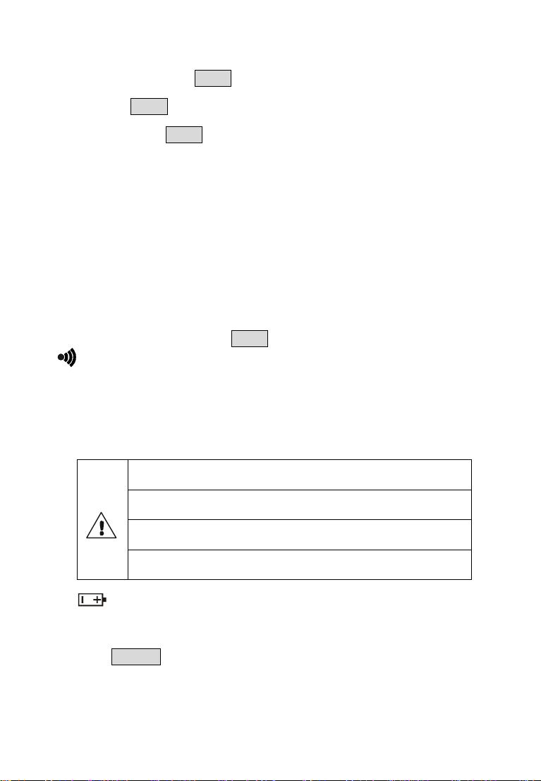
Warning! Make sure the battery cover is well closed
Take note of the battery polarity, otherwise it
may
If the battery power is not enough, please change in
Take out the batteries if you expect not to use the
mode, press HOLD key to exit data access, return back to test mode. In
PEAK mode, press PEAK key to exit PEAK mode, return back to test mode.
After deleting data, it will automatically return back to test mode.
7. PEAK Measurement
The maximum current measurement, during measurement, the meter can
automatically compare the changed current, and keep the maximum one.
When take the meter away from the measured wire, the measured value can
also be kept, so this mode is suitable for the measurement in places where is
not easily to read the value displayed on LCD.
In general test mode, press PEAK key to access or exit PEAK test mode.
“ ” symbol displays in PEAK measurement mode. In other mode, should
first exit and return back to test mode, and then operate PEAK measurement
as above steps.
IX. Battery Replacement
before measurement, otherwise there will be danger.
cause damage to the instrument.
time.
meter for a long time.
1.“ ”is displayed when the power voltage is lower than 5.2V, indicating
that the battery should be replaced.
2. Press POWER key, make sure the meter is power off. Loosen the battery
cover screw, open the plate, replace new batteries and cover the plate,
then tighten screw.
-10-
Page 13
3. Press POWER key to check whether the batteries are successfully
replaced, repeat step 2 if it doesn’t work.
XI. Accessories
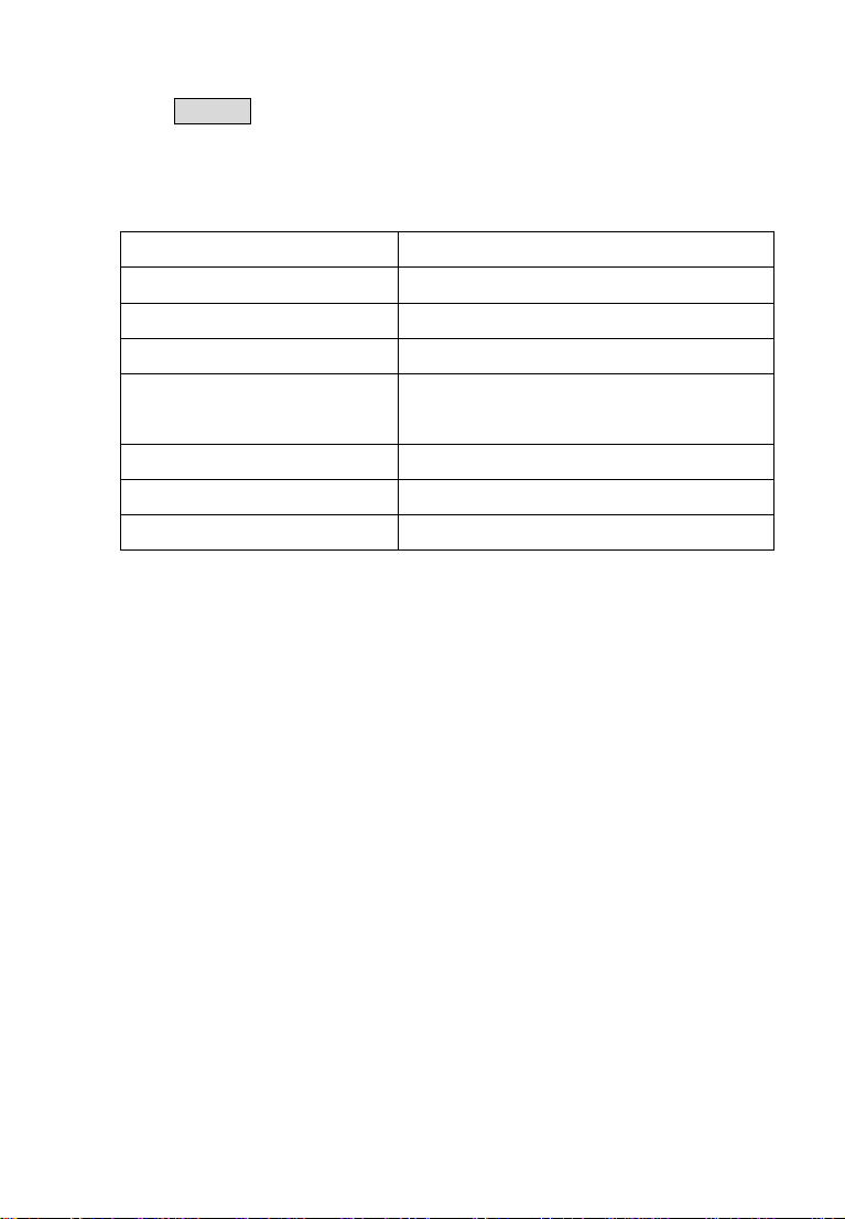
Main Unit 1 piece
Meter Box 1 piece
RS232 Data Line 1 piece
Disk 1 piece
Battery
User Manual 1 piece
Guarantee Card 1 piece
Certification 1 piece
4 pieces(Alkaline Dry Battery LR6)
-11-
Page 14
Manufactured by
ETCR Electronic Technology Company
Address: F-3F, No.4 Pengshang Zhifu Road, Jiahe, Baiyun
District, Guangzhou, Guangdong, China
Post Code: 510440
Tel: (86-20)62199556 62199554
Fax: (86-20)62199550
E-mail: [email protected]
Website: www.etcr.cc
 Loading...