

Page 1

Source Four PAR Nel
Assembly Guide
Page 2

Table of Contents
Final Assembly........................................................................3
Lamp Burner Assembly...........................................................4-5
Housing Assembly..................................................................6-7
Installing a stippled/wave lens ................................................7
Positioning the stippled/wave lens..........................................7
Cleaning the reflector..............................................................8
Source Four PARNel Assembly Guide 2
Page 3
17
5
6
13
11
21
1
2
3
4
12
16
14
15
13
11
12
7
8
10
9
18
19
20
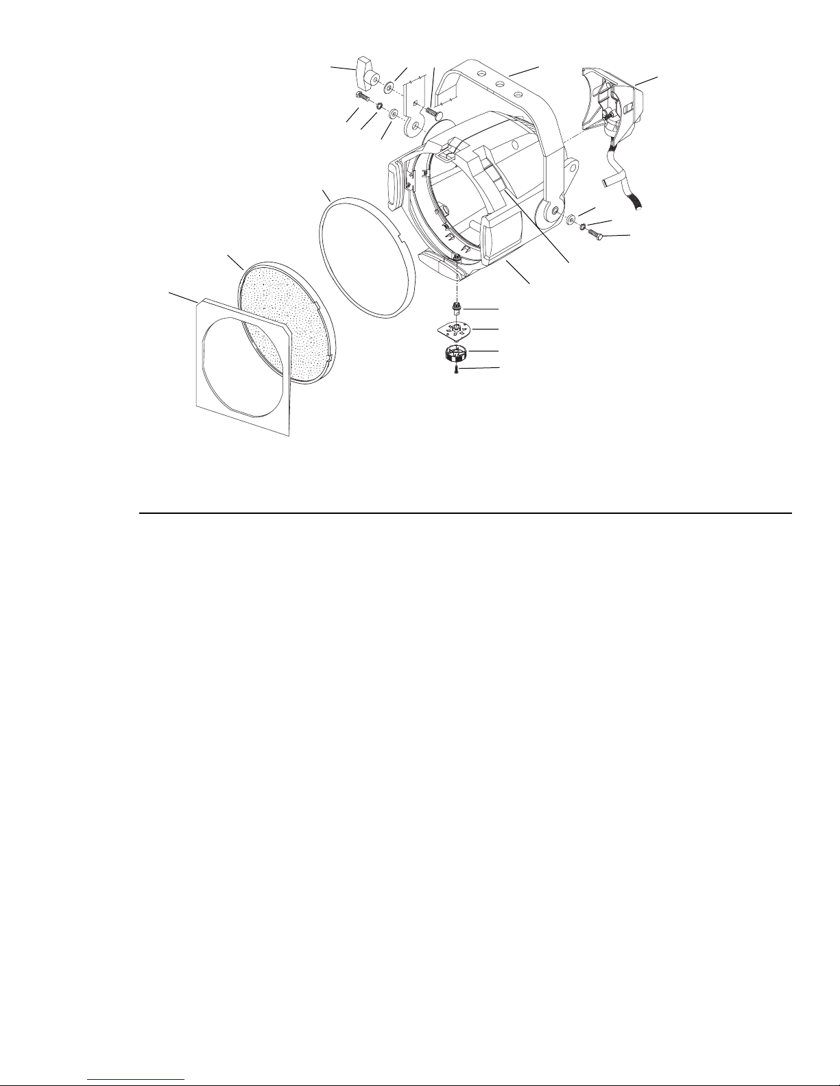
Figure 1
Final Assembly
Refer ence
Number
1 7061A2020 S4 PAR zoom base assembly, black 1
2 7061A2020-1 S4 PAR zoom base assembly, white 1
3 7061A2001 Lamp socket assembly, black 1
4 7061A2001-1 Lamp socket assembly, white 1
5 7061A3006 Yoke bracket, black 1
6 7061A3006-1 Yoke bracket, white 1
7 7061A4010-2 PAR zoom clear/wave lens 1
8 7061A4010-1 PAR zoom stippled/wave lens 1
9 HW5125 Bolt, carriage 5/16-18 X .75” BO 1
10 HW5126 Washer, flat .375 X .875 X .078 B/Z 1
11 HW5139 Washer, 1/4 split ring lock, B/Z 2
12 HW5172 Bolt, hex 1/4-20 X 1.0” grade 5 B/Z 2
13 HW522 Washer, flat 1/4 B/Z 2
14 HW8144 Handle, yoke knob, black 1
15 HW8144-01 Handle, yoke knob, white 1
16 7061A3007 PAR gel frame, 7.25” 1
17 7061A4014 Focus knob gear 1
18 7061A4013 Focus knob bushing 1
19 7061A4015 Focus knob 1
20 HW2154 Screw, PPH, 6-19 X 1/2L, 48-2 Plastite 1
21 7061A4012 Lens rotator 1
Part
Number
Description Quantity
Required
Source Four PARNel Assembly Guide 3
Page 4
6
10
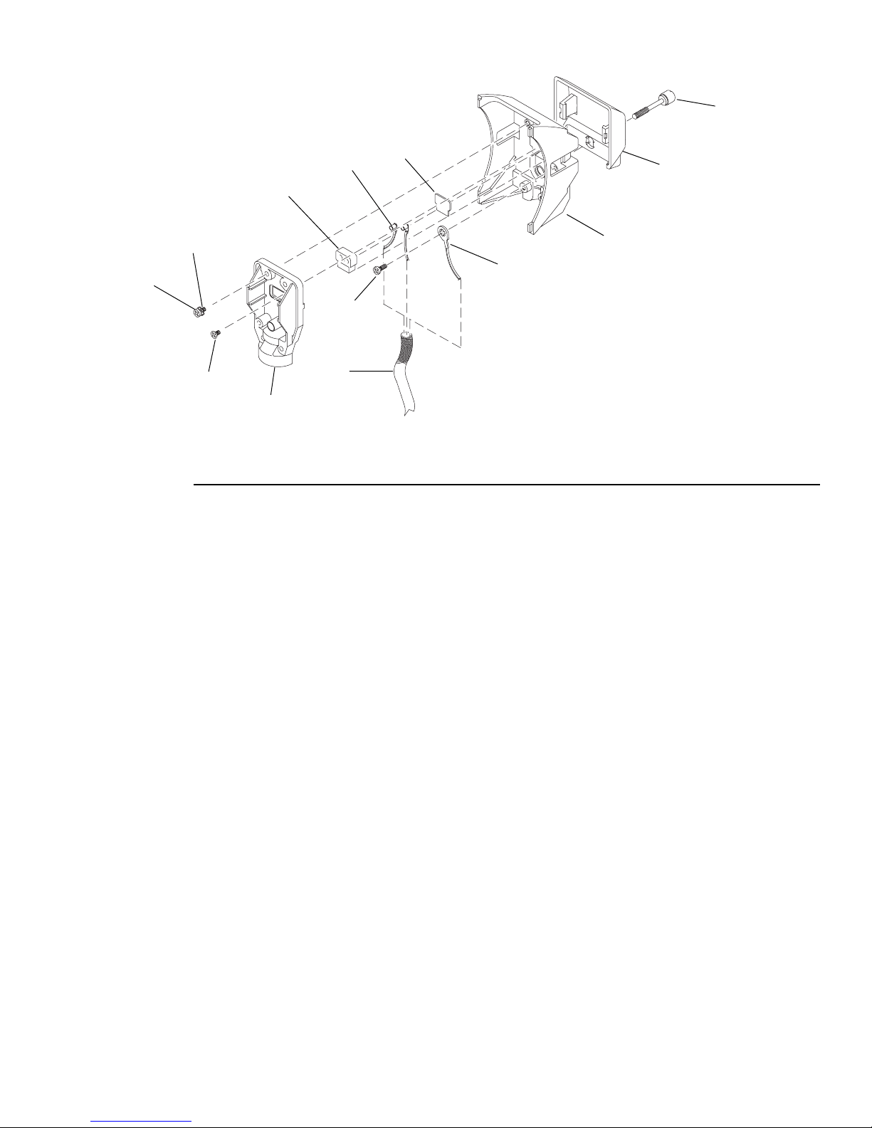
Lamp Burner Assembly
Reference
Number
1 7061A3023 Burner, casting, black 1
2 7061A3024 Strain relief, casting, black 1
3 W330-02 TP22 CLCM assembly, ceramic 1
4 W330-03 TP22 CLCM assembly, mica 1
5 W330-0 1 TP22 CLCM assembly, 44” 1 6-A WG. 1/4” semi-stripped, silv er contacts,
6 7060A3025 Screw, 1/4-20, knurled head 1
7 7061B7002 48” W420 wire, 16-AWG, 200ºC/300V, green, UL 1180/CSA AWM with
8 HW206 Screw, 6-32 X 3/8, black zinc 1
9 HW349 Washer, #8 4
10 HW394 Screw, 8-32 X 1/2, PhPHMS 4
11 HW2125 Screw, 6-32 X 1/4, self tap, black zinc 1
12 W689 Sleeve, fiberglass 1
13 7061A4011 Handle 1
Part
Number
5
3
9
8
11
2
12
4
13
1
7
Figure 2
Description Quantity
Required
2
250º
1
J3209 #6 tooth ring crimp lug installed
Source Four PARNel Assembly Guide 4
Page 5
Lamp Burner Assembly
Tools required: Phillips screwdriver
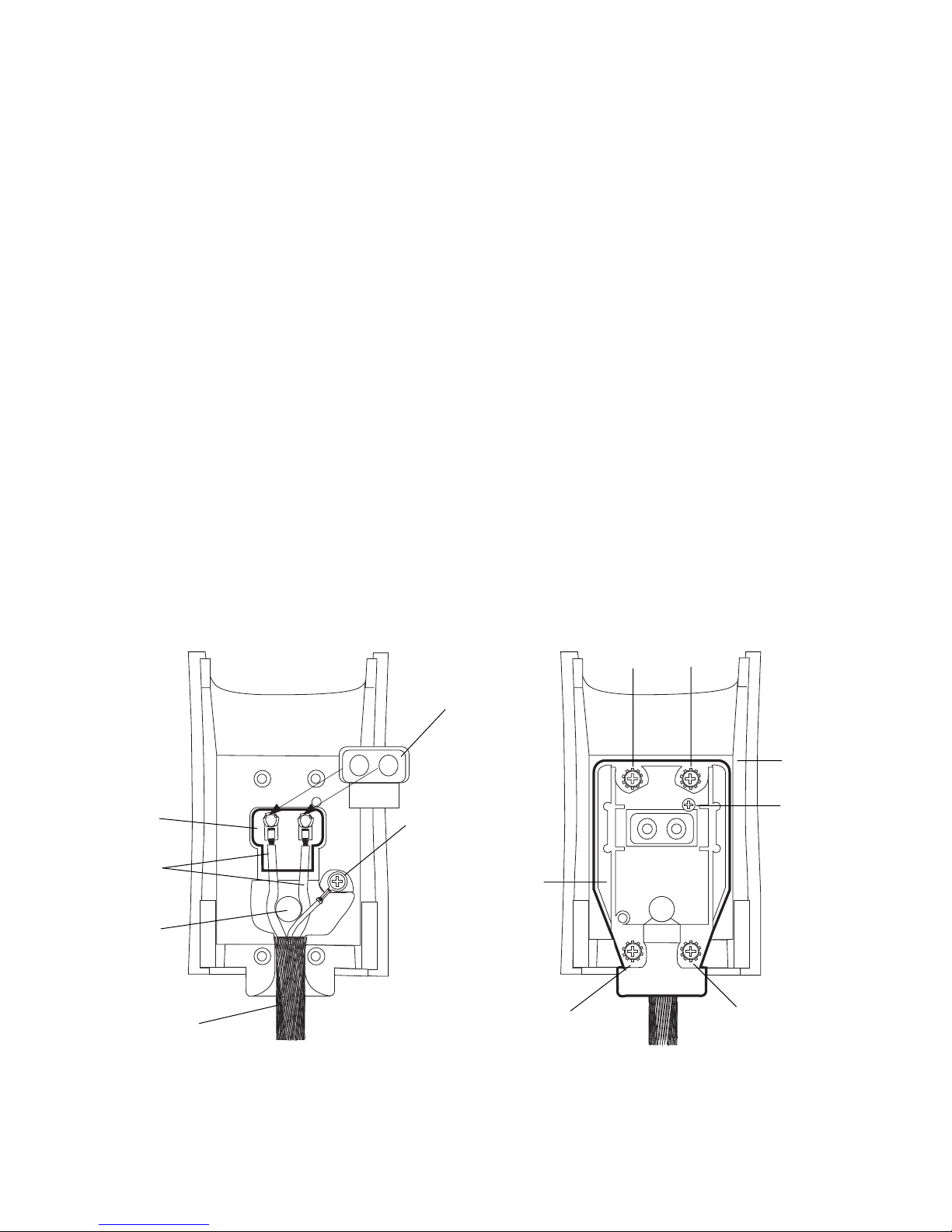
1. Install the ground wire (7) and the two TP22 white leads (5) in the sleeving (12).
2. Snap the focus handle (13) onto the burner (1). (Figure 2)
3. Place the TP22 mica (4) in the burner casting (1), as shown in figure 3.
4. Secure the ground wire lug (7) with prongs down, onto the burner casting (1), using 6-32x3/8” screw (8).
5. Place the TP22 contacts (5) into the grooves on back of the ceramic, and then place on the mica (4). Bend the TP22
white leads as necessary to position around the knurled head screw hole, see figure 3.
Note : Position the wires with the green ground wire on top of the two TP22 white leads. Make sure the green ground
wire is not touching any part of the burner casting.
6. Insert the 8-32x1/2” screws (10), into the washers (9) and place in four positions (as numbered in figure 4) in the strain
relief casting (2).
7. Position the sleeving assembly (12), as shown in figure 3. Fold the sleeving so it fits cleanly in the slot between the
burner and the strain relief.
8. Place the strain relief (2) on the burner casting (1). Loosely attach the washers (9) and screws (10). The ceramic (3)
must be centered in the opening in the strain relief (2). (Figure 4)
WARNING! Make sure that both of the TP22 contacts are centered in the opening in the ceramic and the ceramic is
centered in the opening in the strain relief casting. To center the TP22 contacts, place a small screwdriver (or other
small tipped device) in the center of the TP22 contacts and maneuver them until they are centered in the ceramic.
Failure to center the TP22 contacts and/or the ceramic can cause problems with inserting lamps.
9. Tighten the screws in the order shown in figure 4, to guard against stripping the screws. Make sure the assembly
remains centered, if it doesn’t, loosen the screws and readjust. (You may want to keep the screwdriver in place in the
TP22 contacts while tightening the screws.)
10. Install the 6-32x1/4” screw (11) into the strain relief. (Figure 4)
11. Make sure the focus handle is secure, then insert the knurled head screw (6) through the handle (13) into burner casting (1).
mica (4)
TP22 contact
and lead (5)
knurled head
screw hole
sleeving (12)
ceramic (3)
ground wire (7) and
6-32 X 3/8 screw (8)
strain relief
casting (2)
Figure 3
2
1
4
burner
casting (1)
6-32 X 1/4”
screw (11)
3
Source Four PARNel Assembly Guide 5
Page 6
3
7
9
8
Rear lens track
11
2
21
4
16
18
17
23
19
15
14
20
12
13
1
22
5
6
10
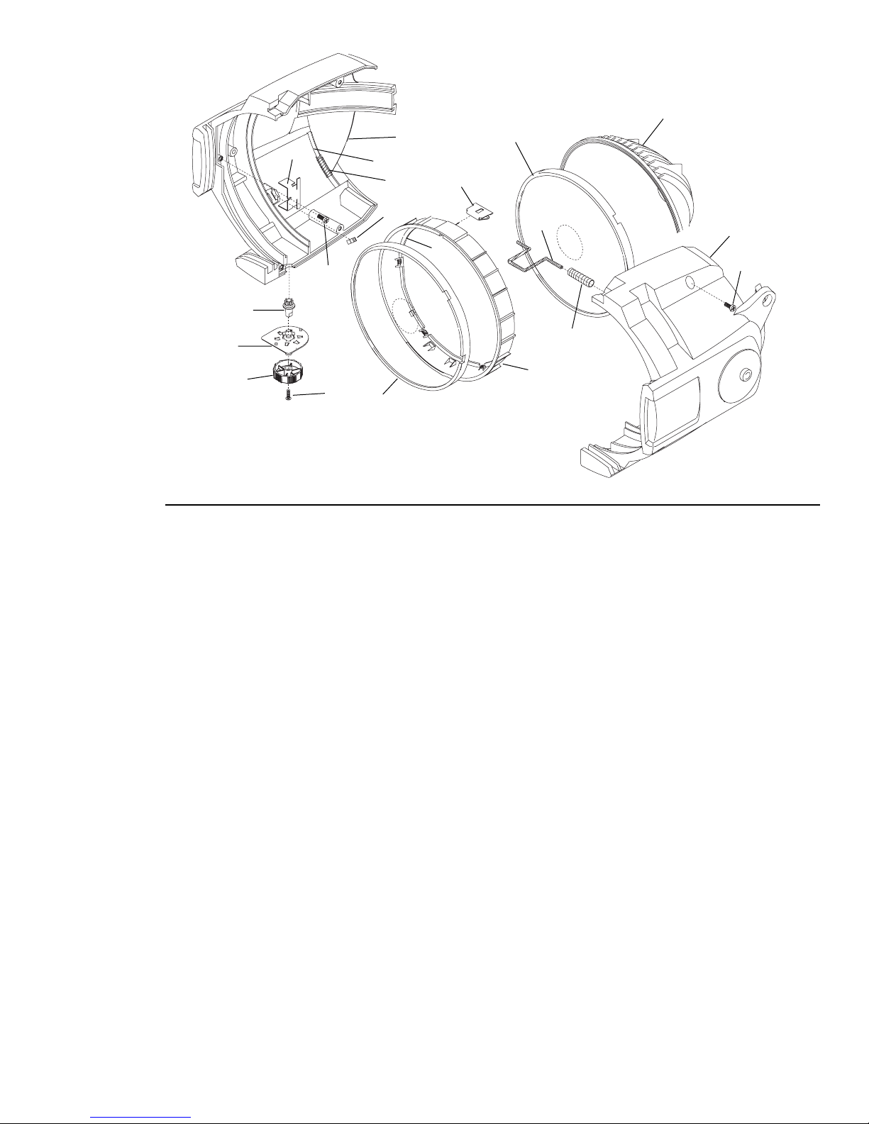
Figure 4
Housing Assembly
Reference Number Part Number Description Quantity Required
1 7061A3005 Gel retainer clip 1
2 7061A3013 Spring clip rotator 1
3 7061A3014 Reflector, painted black 1
4 7061A3014-1 Reflector, painted white 1
5 7061A3025 Barrel, painted black 1
6 7061A3025-1 Barrel, painted white 1
7 70612019 Source Four PAR rivet assembly, black 1
8 70612019 Source Four PAR rivet assembly, white 1
9 70613029 Rotator pressure clip 1
10 HW492 Screw, 10-32 X 5/8, PhPH Taptite 3
11 7061A4001 Pad, silicon reflector mount 2
12 70614012 Lens rotator, black 1
13 70614012-1 Lens rotator, white 1
14 7061A4029 Lens stop 1
15 7061A4020 PARNel lens pad 4
16 7061A4013 Focus knob bushing 1
17 7061A4014 Focus knob gear 1
18 7061A4015 Focus knob 1
19 HW2154 Screw, PPH, 6-19 X 1/2L, 48-2 Plastite 1
20 7061A4010-1 PAR zoom wave/stippled lens 1
21 7061A4010-2 PAR zoom wave/clear lens 1
22 HW750 Spring, retainer 1
23 HW4145 Screw, 10-32 X 3/8, PhPH Taptite, BO 1
Source Four PARNel Assembly Guide 6
Page 7
s
Figure 7
Spring clip
Retaining clip
Housing Assembly
Tools required: Phillips screwdriver.
1. Install the reflector mount silicon pads (11) and lens pad (15) in the left barrel (7 or 8).
2. With the wave side of the lens facing toward the front of the fixture, install the wave/clear lens (21) into the rear lens
track.
3. Assembly items 16, 17 18 and 19 (Focus knob assembly). Rotate the focus knob full spot position. The arrow on the
focus knob will point approximately to the 11 O’clock position.
4. Place the focus knob assembly into the left barrel.
5. Install the lens stop (14) and the rotator spring clip (12) into the lens rotator (12 or 13).
6. Install the lens rotator into the left barrel.
7. Install the rotator pressure clip (9) into the left barrel with screw (23).
8. Install the gel retainer clip (1) and the spring (22) into the right barrel (5 or 6).
9. Attach the right barrel to the left barrel using screws (3) in three places.
10. Check that the gel clip retainer (1) moves easily into position.
11. Check for smooth rotation of the lens rotator (12 or 13).
12. With the wave side facing inward, install the wave/stippled lens (20) into the lens rotator. See below for detailed
instructions on installing the front lens.
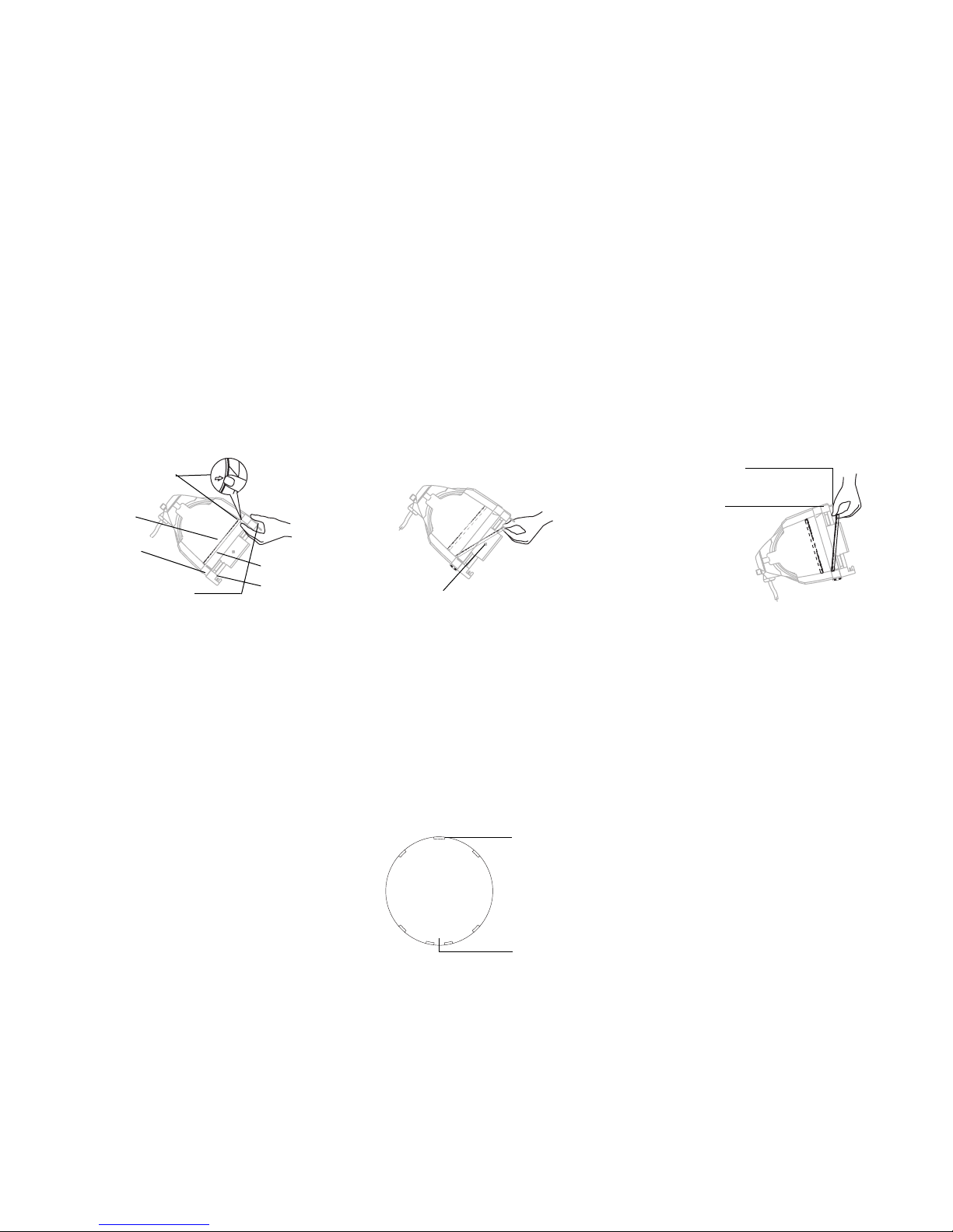
Spring clip
W/C lens
Focus knob
Retaining clip
Figure 5
W/S len
Tab
Lens catcher
Figure 6
Installing a stippled/wave lens
1. Position the fixture with the front of the unit facing you, and tilted slightly down.
2. Rotate the focus knob to the full spot position.
3. Hold the lens by the edge, and position it so the wave side faces the rear of the fixture.
4. From the top of the fixt ure, slide the lens behind the lens catchers and position its base behind the tabs on the bottom
forth lens rotator ring.
5. Gently push the top of the lens inward until it snaps behind the spring clip.
Top center notch
Bottom two
Figure 8
center notches
Positioning the stippled/wave lens
1. There are seven “notches” cut into the stippled side of the lens. Position the lens so that the cluster of three notches
is on top. The center notch of the cluster coincides with the spring clip on the lens retaining ring.
2. The bottom of the lens has a cluster of four notches. Place the two center notches behind the tabs at the bottom of
the lens rotator ring.
Source Four PARNel Assembly Guide 7
Page 8

Cleaning the reflector
Warning : Do not use glass and window cleaners on the reflector. Chemicals in these cleaners will harm the reflective
coating.
Do not use paper towels or harsh materials to wipe the reflector. These materials can scratch the surface of the
reflector .
1. Since the rear (wave/clear) lens is fixed in it’s position, the fixture will need to be dissembled before you can clean the
reflector. See “Housing Assembly” on page 7.
2. Remove the dust with a blast of oil-free air, or wipe with a clean, soft, lint-free cotton cloth.
3. If the reflector is still very dirty, dampen a clean cloth with a mild, soapy water solution (Ivory works well) and gently
wipe the reflector.
4. Remove any soapy water residue with a damp soft cloth.
5. Reassemble the fixture.
Electronic Theatre Controls
North America 3030 Laura Lane • Middleton, Wisconsin 53562 • USA • Tel: (+1) 608 831 4116 • Fax: (+1) 608 836 1736
Europe 5 Victoria Industrial Estate • Victoria Road • London W3 6UU • Tel: (+44) 181 896 1000 • Fax: (+44) 181 896 2000
Asia Room 605-606 • Tower III • Enterprise Square • 9 Sheung Yuet Road • Kowloon Bay • Hong Kong • Tel: (+852) 2799 1220 • Fax: (+852) 2799 9325
World Wide Web: http://www.etcconnect.com • Email: [email protected]
Specifications subject to change. Source Four PAR is protected by US patent numbers 5,268,613.
US and International Patents Pending. 7061M1010 Rev. B
Copyright 2004
Revised 01/2004
 Loading...