

Page 1
ETC Installation Guide
Source Four Mini™ LED Canopy and Track Mount Kits
Corporate Headquarters
3031 Pleasant View Road, P.O. Box 620979, Middleton, Wisconsin 53562-0979 USA Tel +608 831 4116 Fax +608 836 1736
London, UK
Unit 26-28, Victoria Industrial Estate, Victoria Road, London W3 6UU, UK Tel +44 (0)20 8896 1000 Fax +44 (0)20 8896 2000
Rome, IT
Via Pieve Torina, 48, 00156 Rome, Italy Tel +39 (06) 32 111 683 Fax +44 (0)20 8752 8486
Holzkirchen, DE
Ohmstrasse 3, 83607 Holzkirchen, Germany Tel +49 (80 24) 47 00-0 Fax +49 (80 24) 47 00-3 00
Hong Kong Rm 1801, 18/F, Tower 1 Phase 1, Enterprise Square, 9 Sheung Yuet Road, Kowloon Bay, Kowloon, Hong Kong Tel +852 2799 1220
Service:
(Americas) [email protected]
(UK) [email protected] (DE) [email protected]
(Asia) [email protected]
Web:
www.etcconnect.com
Copyright © 2014 ETC. All Rights Reserved. Product information and specifications subject to change.
7063M2110
Rev A Released 2014-02 ETC intends this document to be provided in its entirety.
Introduction
This guide illustrates the installation of the Canopy and Track Mount kits for the
Source Four Mini LED fixture. For additional information, see the Source Four
Mini LED User Manual that shipped with your fixture.
WARNING:
TURN OFF POWER at main fuse or breaker box and verify
that the power is off before proceeding with installation.
Wiring must meet local and national codes.
Do not mount the fixture on or near combustible surfaces.
Do not operate the fixture without a lens installed.
Always hang the fixture with the color frame retaining clip in the
locked position.
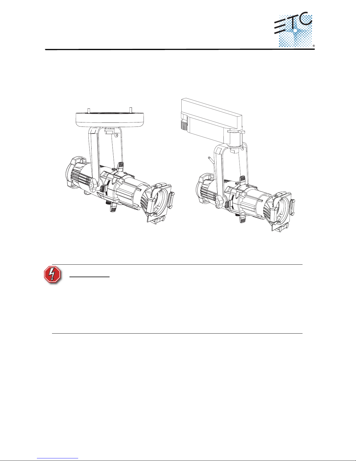
Canopy mount
Track mount
Page 2
ETC Installation Guide
Source Four Mini LED
Canopy and Track Mount Kits Page 2 of 4
Canopy Installation Procedure
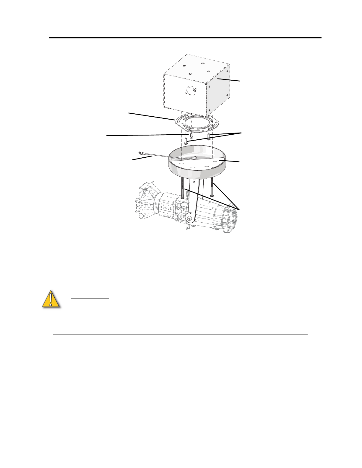
Step 1: Remove the mounting plate from the fixture by removing the two
canopy screws and the ground screw. Set the ground screw safely
aside.
Step 2: Using the mounting plate screws, secure the mounting plate to the
installed electrical box, which is not included.
CAUTION:
The metal canopy plate has built in indentations allowing
the mounting plate screws to nest into the canopy plate.
For an ideal flush mount installation you may need to
rotate the plate to accommodate these indentations. See
the following graphic for additional information.
Back box
(not provided)
Mounting
plate
Canopy
screws
Ground
braid
Mounting plate
screws
Canopy plate: the four
indentations allow for
multiple screw nesting
positions.
Ground
screw
Page 3

ETC Installation Guide
Source Four Mini LED
Page 3 of 4 Canopy and Track Mount Kits
Step 3: Place the copper ground braid loop over the ground screw and attach
the ground screw to the back box.
Step 4: Connect the building ground wire to the ground wire on the fixture,
following local electrical codes.
Step 5: Connect your supply power wires to the lamp wiring using the included
two-position Wagos.
For 120V fixtures: Connect the black wire to line and the white wire to neutral.
For 230V fixtures: Connect the brown wire to line and the blue wire to neutral.
Step 6: While keeping in mind the mounting plate orientation, use the canopy
screws to secure the fixture to the mounting plate.
Step 7: Open all four of the shutter blades by sliding them outward until they
stop.
Step 8: Install a gobo and gel as desired and confirm that they are properly
secured.
Step 9: Restore power at the main fuse.
Step 10: Focus the fixture as desired.
Canopy
screw
hole
3
2
1
3
2
1
Mounting plate screw
installation detail
Canopy
screw
hole
Install the mounting
plate screws in one of
the three positionpairings shown.
Only the slots on the
outer circumference
will allow a true flush
mounting.
Page 4
ETC Installation Guide
Source Four Mini LED
Canopy and Track Mount Kits Page 4 of 4
Track Installation Procedure
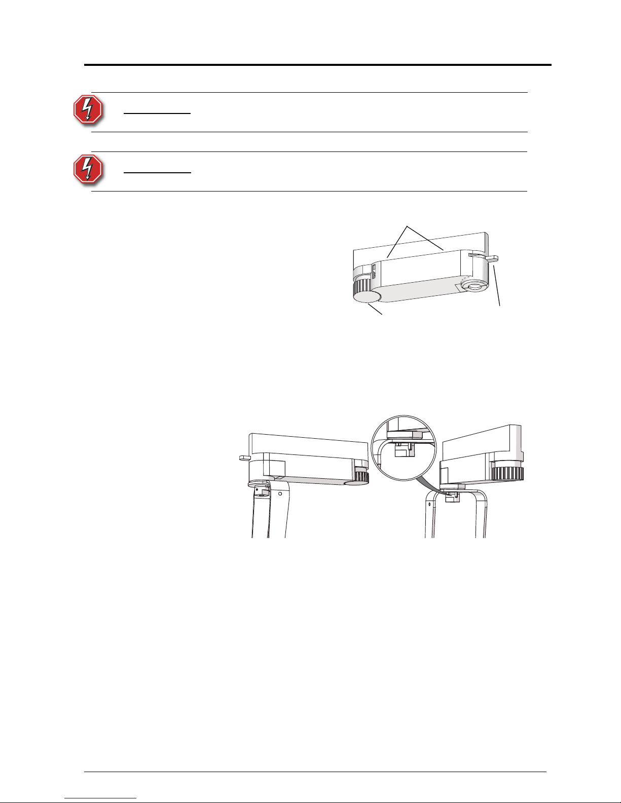
Step 1: Insert the track adapter into the
track. The adapter will only fit one
way into the track with the tabs of
the adapter in the groove of the
track.
Step 2: Lock the adapter into place.
Step 3: Select circuit 1 or 2 using the
circuit selection wheel.
The 230V track adapter has a threecircuit selector knob.
Step 4: Focus the fixture.
Step 5: Lock the fixture into place using the yoke lock.
WARNING:
To reduce the risk of fire and electric shock, use only with
EUTRAC track system.
AVERTIR:
Réduire le risque de feu et la décharge électrique, l'usage
seulement avec le systéme de piste d'EUTRAC.
Circuit selection
wheel
Lock
Tabs
There are cable protection posts
on both the yoke lock and the
yoke that prevent the fixture from
rotating a full 360°.
The yoke can be locked into
place using a 1.5mm Allen
wrench.
 Loading...