

Page 1

User Manual
v1.5
Rev A
The Source Four LED series of fixtures are intended for professional use only.
Read entire User Manual before using equipment.
Profile
Copyright © 2013 Electronic Theatre Controls, Inc.
All rights reserved.
Product information and specifications subject to change.
Part Number:
7460M1200-1.5.0
Rev A
Released: 2013-09
Page 2

ETC® permits the reproduction of materials in this manual only for non-commercial purposes. All other rights
are reserved by ETC.
ETC intends this document, whether printed or electronic, to be provided in its entirety.
ETC is a registered trademark of Electronic Theatre Controls, Inc. in the United States and other countries.
Other product and company names mentioned herein may be trademarks and/or service marks of their respective
owners.
This product is protected by one or more of the following U.S. Patents: 6,016,038, 6,150,774, 6,788,011,
6,806,659, 6,683,423 and 7,023,543
US and international patents pending.
Page 3

Source Four LED Profile v1.5.0 User Manual i
Table of Contents
Introduction . . . . . . . . . . . . . . . . . . . . . . . . . . 1
Quick Setups . . . . . . . . . . . . . . . . . . . . . . . . . . . . . . . . . . . . . . . . . . .1
Lustr+ . . . . . . . . . . . . . . . . . . . . . . . . . . . . . . . . . . . . . . . . . . . . . .1
Studio HD . . . . . . . . . . . . . . . . . . . . . . . . . . . . . . . . . . . . . . . . . . .1
Daylight and Tungsten . . . . . . . . . . . . . . . . . . . . . . . . . . . . . . . . .2
Fixture Components . . . . . . . . . . . . . . . . . . . . . . . . . . . . . . . . . . . . . .3
Models . . . . . . . . . . . . . . . . . . . . . . . . . . . . . . . . . . . . . . . . . . . . . . . .4
Applications . . . . . . . . . . . . . . . . . . . . . . . . . . . . . . . . . . . . . . . . . . . .5
Document Conventions . . . . . . . . . . . . . . . . . . . . . . . . . . . . . . . . . . .5
Notices . . . . . . . . . . . . . . . . . . . . . . . . . . . . . . . . . . . . . . . . . . . . .5
Typography Used in This Guide . . . . . . . . . . . . . . . . . . . . . . . . . .5
Safety . . . . . . . . . . . . . . . . . . . . . . . . . . . . . . . . . . . . . . . . . . . . . . . . .6
Contacts . . . . . . . . . . . . . . . . . . . . . . . . . . . . . . . . . . . . . . . . . . . . . . .7
Quick Start . . . . . . . . . . . . . . . . . . . . . . . . . . 9
Install . . . . . . . . . . . . . . . . . . . . . . . . . . . . . . . . . . . . . . . . . . . . . .9
Connect . . . . . . . . . . . . . . . . . . . . . . . . . . . . . . . . . . . . . . . . . . . . .9
Focus. . . . . . . . . . . . . . . . . . . . . . . . . . . . . . . . . . . . . . . . . . . . . . .9
Configure. . . . . . . . . . . . . . . . . . . . . . . . . . . . . . . . . . . . . . . . . . .10
Soft Focus Diffuser . . . . . . . . . . . . . . . . . . . . . . . . . . . . . . . . . . .10
Quick Color Menu (Lustr+ and Studio HD only) . . . . . . . . . . . . .10
Quick Setups Menu . . . . . . . . . . . . . . . . . . . . . . . . . . . . . . . . . . .11
Installation and User Interface Overview . . 13
Specifications . . . . . . . . . . . . . . . . . . . . . . . . . . . . . . . . . . . . . . . . . .14
Typical Power Consumption. . . . . . . . . . . . . . . . . . . . . . . . . . . . . . .15
Note About LED Fixtures . . . . . . . . . . . . . . . . . . . . . . . . . . . . . . . . .16
Color Rendering Index and Color Quality Scale Ratings . . . . . . . . .16
Hardware . . . . . . . . . . . . . . . . . . . . . . . . . . . . . . . . . . . . . . . . . . . . .17
Basic Assembly . . . . . . . . . . . . . . . . . . . . . . . . . . . . . . . . . . . . . .17
Mounting Hardware . . . . . . . . . . . . . . . . . . . . . . . . . . . . . . . . . . .17
Install Lens Tube . . . . . . . . . . . . . . . . . . . . . . . . . . . . . . . . . . . . .18
Aim Adjustments . . . . . . . . . . . . . . . . . . . . . . . . . . . . . . . . . . . . .19
Focusing the Beam . . . . . . . . . . . . . . . . . . . . . . . . . . . . . . . . . . .20
Shaping the Beam. . . . . . . . . . . . . . . . . . . . . . . . . . . . . . . . . . . .20
Soft Focus Diffuser . . . . . . . . . . . . . . . . . . . . . . . . . . . . . . . . . . .21
Rotating the Shutter Barrel Assembly . . . . . . . . . . . . . . . . . . . . .22
Adjusting the C-clamp For North America. . . . . . . . . . . . . . . . . .22
Adjusting the Yoke Position. . . . . . . . . . . . . . . . . . . . . . . . . . . . .24
Installation Clearances . . . . . . . . . . . . . . . . . . . . . . . . . . . . . . . . . . .25
Cooling and Duty Cycle. . . . . . . . . . . . . . . . . . . . . . . . . . . . . . . .25
Dimensions and Hanging Clearances . . . . . . . . . . . . . . . . . . . . . . .26
Page 4

ii Source Four LED Profile v1.5.0 User Manual
Safety Cable. . . . . . . . . . . . . . . . . . . . . . . . . . . . . . . . . . . . . . . . . . .27
Fixture Weight . . . . . . . . . . . . . . . . . . . . . . . . . . . . . . . . . . . . . . . . .27
Power and Data Cabling Requirements . . . . . . . . . . . . . . . . . . . . . .28
Power . . . . . . . . . . . . . . . . . . . . . . . . . . . . . . . . . . . . . . . . . . . . .28
Data. . . . . . . . . . . . . . . . . . . . . . . . . . . . . . . . . . . . . . . . . . . . . . .28
Connections . . . . . . . . . . . . . . . . . . . . . . . . . . . . . . . . . . . . . . . . . . .29
Source Four LED Series Connections . . . . . . . . . . . . . . . . . . . .29
Indicator Lights . . . . . . . . . . . . . . . . . . . . . . . . . . . . . . . . . . . . . .29
DMX Profile . . . . . . . . . . . . . . . . . . . . . . . . . . . . . . . . . . . . . . . . . . .30
Addressing . . . . . . . . . . . . . . . . . . . . . . . . . . . . . . . . . . . . . . . . .30
Profiles . . . . . . . . . . . . . . . . . . . . . . . . . . . . . . . . . . . . . . . . . . . .30
Daylight and Tungsten Profiles . . . . . . . . . . . . . . . . . . . . . . . . . .34
DMX Footprints and Channel Mapping . . . . . . . . . . . . . . . . . . . . . .35
Tungsten and Daylight . . . . . . . . . . . . . . . . . . . . . . . . . . . . . . . .35
Lustr+ and Studio HD . . . . . . . . . . . . . . . . . . . . . . . . . . . . . . . . .35
Installing Accessories. . . . . . . . . . . . . . . . . . . . . . . . . . . . . . . . . . . .36
Color Frame Holder. . . . . . . . . . . . . . . . . . . . . . . . . . . . . . . . . . .36
Basic Menu Navigation . . . . . . . . . . . . . . . . 38
User Interface Overview. . . . . . . . . . . . . . . . . . . . . . . . . . . . . . . . . .39
LCD . . . . . . . . . . . . . . . . . . . . . . . . . . . . . . . . . . . . . . . . . . . . . . .39
Keypad . . . . . . . . . . . . . . . . . . . . . . . . . . . . . . . . . . . . . . . . . . . .40
Keypad Lockout. . . . . . . . . . . . . . . . . . . . . . . . . . . . . . . . . . . . . .40
Status Indicators . . . . . . . . . . . . . . . . . . . . . . . . . . . . . . . . . . . . .41
Screen Navigation . . . . . . . . . . . . . . . . . . . . . . . . . . . . . . . . . . . .41
Status (Home) Screens . . . . . . . . . . . . . . . . . . . . . . . . . . . . . . . .42
Menu Navigation . . . . . . . . . . . . . . . . . . . . . . . . . . . . . . . . . . . . .43
Operation . . . . . . . . . . . . . . . . . . . . . . . . . . 44
Home Screen Displays. . . . . . . . . . . . . . . . . . . . . . . . . . . . . . . . . . .45
Main Menu . . . . . . . . . . . . . . . . . . . . . . . . . . . . . . . . . . . . . . . . . . . .47
DMX Start Address . . . . . . . . . . . . . . . . . . . . . . . . . . . . . . . . . . .47
Quick Setups . . . . . . . . . . . . . . . . . . . . . . . . . . . . . . . . . . . . . . . .47
Advanced Settings . . . . . . . . . . . . . . . . . . . . . . . . . . . . . . . . . . .48
Advanced Menu . . . . . . . . . . . . . . . . . . . . . . . . . . . . . . . . . . . . . . . .49
DMX Settings . . . . . . . . . . . . . . . . . . . . . . . . . . . . . . . . . . . . . . .49
LED Settings . . . . . . . . . . . . . . . . . . . . . . . . . . . . . . . . . . . . . . . .53
Presets & Sequences . . . . . . . . . . . . . . . . . . . . . . . . . . . . . . . . .57
Quick Color (Lustr+, Studio HD) . . . . . . . . . . . . . . . . . . . . . . . . .67
Diagnostics . . . . . . . . . . . . . . . . . . . . . . . . . . . . . . . . . . . . . . . . .68
Local Settings . . . . . . . . . . . . . . . . . . . . . . . . . . . . . . . . . . . . . . .73
Copy All Settings . . . . . . . . . . . . . . . . . . . . . . . . . . . . . . . . . . . . .76
Studio Settings . . . . . . . . . . . . . . . . . . . . . . . . . . . . . . . . . . . . . . . . .77
Lustr+ and Studio HD . . . . . . . . . . . . . . . . . . . . . . . . . . . . . . . . .77
Daylight and Tungsten . . . . . . . . . . . . . . . . . . . . . . . . . . . . . . . .79
Error Messages . . . . . . . . . . . . . . . . . . . . . . . . . . . . . . . . . . . . . . . .80
Software Updates. . . . . . . . . . . . . . . . . . . . . . . . . . . . . . . . . . . . . . .81
ETC Technical Support . . . . . . . . . . . . . . . . . . . . . . . . . . . . . . . .81
Page 5

iii
Routine Maintenance . . . . . . . . . . . . . . . . . . . . . . . . . . . . . . . . . . . .82
Cleaning the Field Lens. . . . . . . . . . . . . . . . . . . . . . . . . . . . . . . .82
Inspecting and Cleaning the Electronics . . . . . . . . . . . . . . . . . . .83
Menu Flow Chart. . . . . . . . . . . . . . . . . . . . . 84
Home and Main Menus (Lustr+ and Studio HD) . . . . . . . . . . . . .84
Home and Main Menus (Daylight and Tungsten) . . . . . . . . . . . .85
Advanced Menu (Lustr+ and Studio HD) . . . . . . . . . . . . . . . . . .86
Advanced Menu (Daylight and Tungsten) . . . . . . . . . . . . . . . . . .87
Presets Menu (Lustr+ and Studio HD) . . . . . . . . . . . . . . . . . . . .88
Presets Menu (Daylight and Tungsten). . . . . . . . . . . . . . . . . . . .89
Sequences Menu (all fixture types) and
Quick Color Menu (Lustr+ and Studio HD only) . . . . . . . . . . . . .90
Diagnostics Menu . . . . . . . . . . . . . . . . . . . . . . . . . . . . . . . . . . . .91
Diagnostics Test . . . . . . . . . . . . . . . . . . . . . . . . . . . . . . . . . . . . .92
Diagnostics Recalibrate Fixture. . . . . . . . . . . . . . . . . . . . . . . . . .93
Page 6

1 Source Four LED Profile v1.5.0 User Manual
Introduction
Congratulations on your purchase of a Source Four LED series by ETC product.
Source Four LED series’s x7 Color System™ seven-hue technology produces a light and
color quality that conventional LED systems cannot duplicate. This unique color system
produces bright, broad-spectrum whites and intense colors equally well, rendering
pigments, objects, and skin tones in a natural way.
Daylight and Tungsten fixtures use high-output white LEDs for maximum brightness and
efficacy. Tungsten interacts very well with incandescent sources, while Daylight easily
replaces a variety of HMI lamps and natural sunlight.
Quick Setups
You can use any one of the Quick Setups and fine-tune settings for either console operation
via DMX protocol or standalone operation. For advanced users, an expanded user interface
provides easy navigation to all settings and options.
Lustr+
Some of the options include:
• Multiple DMX profiles ranging from a simple 3-channel RGB profile to 8-channel direct
color and intensity control.
• Multiple dimming curve options.
• Preset colors and sequences for standalone operation.
• White point selection; white light and color behavior based on a specific color
temperature white light such as 3200K or 5600K.
• Loss-of-data behavior options.
• Power regulation modes; three output options that offer a choice between maximum
light output for lower duty cycles and maximum thermal stability and output consistency
for higher duty cycles.
Studio HD
• Balanced with x7 Color System for a spectrally rich, variable white light.
• Color temperatures from 2700K to 6500K.
• Onboard +/- green adjustment.
• Preset colors and sequences for stand-alone operation.
• Multiple dimming curve options.
• Power regulation modes; three output options that offer a choice between maximum
light output for lower duty cycles and maximum thermal stability and output consistency
for higher duty cycles.
Page 7

Introduction 2
Daylight and Tungsten
Options include:
• Multiple dimming curve options.
• Presets and sequences for standalone operation.
• Strobe.
• Loss-of-data behavior options.
• Power regulation modes; three output options that offer a choice between maximum
light output for lower duty cycles and maximum thermal stability and output consistency
for higher duty cycles.
Page 8
3 Source Four LED Profile v1.5.0 User Manual
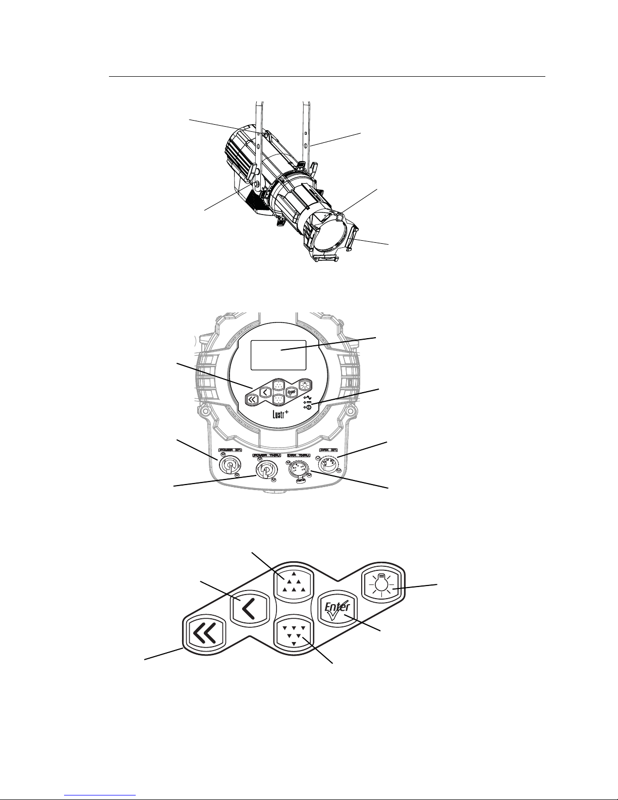
Fixture Components
Figure-1.1 Components of the Source Four LED Profile Fixture.
Figure-1.2 Components of the Rear Panel.
Figure-1.3 Keypad Button Functions.
For information about the user interface, see User Interface Overview, page 39.
Color frame
holder
Accessory
retainer
Safety
cable
loop
Yoke
Yoke
locking
knob
Power In
Power Thru
DMX In
DMX Thru
Status
indicators
LCD
Keypad
Light Bulb
Enter
Down
Up
Back
Home
Page 9

Introduction 4
Models
Each member of the Source Four LED series product line is unique and optimized for a
specific lighting task. All models are compatible with the complete line of Source Four Lens
tubes.
Lustr+
• Specialized x7 LED array with 6 colors plus white
• Broad-spectrum color optimized for the best white and light tints across the entire white
and pastel range
• Beautifully illuminates skin tones and other objects
Studio HD
• A mix of high-output LEDs and carefully selected colors from the x7 spectrum
• Variable color temperature from 2700K to 6500K
• Deep spectrum whites with up to 94 CRI
Daylight
• 5,600K nominal correlated color temperature
• 70 CRI typical
Tungsten
• 3,000K nominal correlated color temperature
• 85 CRI typical
Page 10
5 Source Four LED Profile v1.5.0 User Manual
Applications
Document Conventions
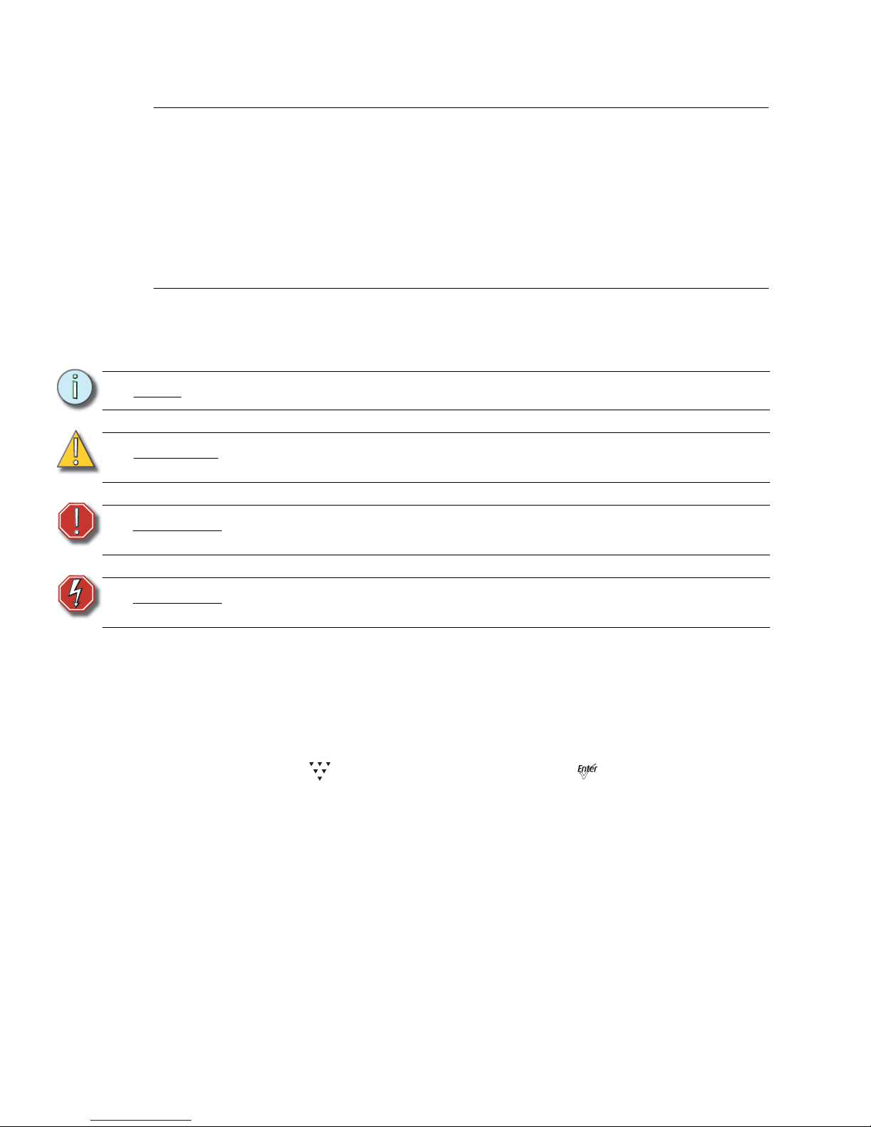
Notices
Throughout this manual, the following are used to alert you to notes and safety notices.
Please email comments about this manual to: [email protected]
Typography Used in This Guide
Menu items and commands you must perform are indicated in bold text. Keypad buttons
are indicated in bold [brackets]. Menu selections or commands appear in bold. For
example:
Press [] to select Sequences and then press [].
• Theaters • Convention centers
• Studios • Theme parks
• Schools • Museums
• Houses of worship • Temporary events
• Hotels
Note:
Notes are helpful hints and information that is supplemental of the main text.
CAUTION:
A Caution statement indicates situations where there may be undefined or unwanted
consequences of an action, potential for data loss or an equipment problem.
WARNING:
A Warning statement indicates situations where damage may occur, people
may be harmed, or there are serious or dangerous consequences of an action.
WARNING:
RISK OF ELECTRIC SHOCK! This warning statement indicates situations
where there is a risk of electric shock.
Page 11
Introduction 6
Safety
The Source Four LED series fixtures are intended for professional use only. Read the
entire User Manual before using equipment.
WARNING:
Note the following safety warnings before use:
• Do not mount the Source Four LED series fixture on or near a flammable
surface.
• Do not use this fixture with a damaged power lead. If the power lead
(cordset) is damaged, it must be replaced.
• Do not use this fixture if glass lens is deeply scratched or cracked.
Damaged lenses must be replaced.
• Use theSource Four LED series fixture in dry locations only, where
humidity does not exceed 90 percent (non-condensing). These fixtures are
not intended for outdoor use.
• Mount and support the fixture only by the primary suspension holes in the
yoke or floor standing yoke.
• Suspend the fixture from a suitable structure using only the hardware rated
for the weight of the fixture.
• In addition to primary suspension, attach a safety cable (ETC Model 400SC
or other approved safety cable or device) to the fixture housing.
Appropriate attachment point (hole) is provided in the protruding tab on the
fixture housing.
• Disconnect the unit from power and from DMX before all cleaning and
maintenance.
Note:
• Maximum recommended ambient operating temperature: Ta=40°C (104°F)
• Maximum anticipated external surface temperature: Tmax=80°C (176°F)
• External temperature after 5 minutes of full-brightness operation at 25°C (77°F)
ambient: 29.9°C (85.8°F)
• External Temperature (steady state achieved) at 25°C (77°F): 41.5°C (106.7°F)
Page 12

7 Source Four LED Profile v1.5.0 User Manual
Contacts
If you have questions about your Source Four LED series fixture that are not answered in
this manual, please contact the supplier of your ETC equipment or ETC Technical Services.
For general information, your most convenient resources are the references provided in this
manual. To search more widely try the ETC web site at www.etcconnect.com.
For technical questions about Source Four LED series fixtures, contact ETC Technical
Services directly at one of the offices listed below. Emergency service is available from all
ETC offices outside of normal business hours.
Please email comments about this manual to: [email protected]
Americas United Kingdom
Electronic Theatre Controls Inc. Electronic Theatre Controls Ltd.
Technical Services Department Technical Services Department
3031 Pleasant View Road 26-28 Victoria Industrial Estate
Middleton, WI 53562 Victoria Road,
800-775-4382 (USA, toll-free) London W3 6UU England
+1-608 831-4116 +44 (0)20 8896 1000
[email protected] [email protected]
Asia Germany
Electronic Theatre Controls Asia, Ltd. Electronic Theatre Controls GmbH
Technical Services Department Technical Services Department
Room 1801, 18/F Ohmstrasse 3
Tower 1, Phase 1 Enterprise Square 83607 Holzkirchen, Germany
9 Sheung Yuet Road +49 (80 24) 47 00-0
Kowloon Bay, Kowloon, Hong Kong [email protected]
+852 2799 1220
[email protected]
Page 13

Introduction 8
Page 14
9 Source Four LED Profile v1.5.0 User Manual
Quick Start
This section will help users to quickly use the Source Four LED fixture. For complete,
detailed information and step-by-step instructions, see Operation, page 44.
Install
Step 1: Hang or mount the fixture using the provided hardware and approved hardware
accessories.
Step 2: Attach an approved safety cable when applicable.
Step 3: Insert additional accessories (top hat, etc.) into the holder, if desired.
Connect
Step 1: Attach the power cable to the Power In connector.
Step 2: Attach 5-pin XLR cable to the DMX In connector (if using external control).
Step 3: Plug the power cable into AC power (100 to 240VAC, 50/60 Hz) on a
non-dimmable circuit.
Step 4: Plug the XLR cable (if using) into the DMX source or data daisy-chain.
Step 5: Link additional fixtures via the Power Out and DMX Out connectors using the
following guidelines.
• No more than 9 total Source Four LED fixtures on Power Thru.
• Up to 32 device loads on the DMX daisy-chain.
Focus
Step 1: With power supplied, wait for the fixture to boot up. This will take approximately
ten seconds.
Step 2: Press [] to open the Presets & Sequences menu.
Step 3: Select Focus and then press []. This turns the LED array on to enable
focusing.
Step 4: Adjust the fixture's position as needed.
Step 5: When focusing is complete, press [] to restore the fixture to its original preset.
Step 6: Select [] to return to the home screen.
For information about the user interface, see User Interface Overview, page 39.
CAUTION:
The fixture must be connected to a non-dimmable power source in order to avoid
damage to its internal power supply and other electrical components. Dimming will
damage the fixture and void the warranty.
Page 15
Quick Start 10
Configure
Set DMX Address
Step 1: From the main screen, press [] to open the Main Menu.
Step 2: On the Main Menu, scroll to DMX Start Address and then press [].
Step 3: Use [] or [] to scroll to the desired address.
Step 4: Press [] to select the address number.
Step 5: Press [] to return to the home screen.
A DMX address is not required if using standalone or master/slave control.
Soft Focus Diffuser
Step 1: Install the Soft Focus diffuser into an A-Sized Pattern holder.
Step 2: Insert the Pattern holder and diffuser into the Pattern holder slot, making sure the
writing on the diffuser faces away from the Light engine.
For more information, see Soft Focus Diffuser, page 21.
Quick Color Menu (Lustr+ and Studio HD only)
When there is no DMX signal to the fixture:
Quick Color allows you to easily select a color and its intensity from a predefined menu.
This feature overrides any presets or sequences previously selected and is only available
when there is no external DMX signal to the fixture. For a list of available colors,
To select a Quick Color:
Step 1: Scroll to Quick Color within the Presets and Sequences screen.
Step 2: Press [].
Step 3: Scroll to Color and press [].
Step 4: Press [] or [] to select the desired color
Step 5: Press [] to commit the selection.
Step 6: Scroll to Intensity and press [].
Step 7: Press and hold [] or [] to adjust the fixture’s intensity.
Step 8: Press [] to commit the selection.
• To set the Intensity to 0, press the []. Pressing [] a second time will
return the fixture to its previously set intensity.
• If power to the fixture is lost while in Quick Color mode, the fixture will return
to the Quick Color menu when power is restored.
Note:
Exiting the Quick Color menu will return the fixture to the state it was in prior to
entering the menu.
Page 16
11 Source Four LED Profile v1.5.0 User Manual
Quick Setups Menu
Various pre-programmed combinations of operational settings are available to quickly get
you started. These settings are specifically created for different situations and are easily
accessible on the fixture’s user interface. Individual settings within each quick setup can be
accessed via the Advanced menu in order to take advantage of all the possible control
features.
Quick Setups (Lustr+ and Studio HD)
Step 1: On the Main Menu, scroll to Quick Setups.
Step 2: Press [].
Step 3: Scroll to the desired setup and then press [].
An asterisk (*) next to the setup name indicates that setup is active.
Step 4: Press [] to return to the home screen.
The top line of the home screen displays the name of the active setup.
Quick Setup Description Profile Features
General
General lighting:
All-purpose settings for most lighting
applications.
The default setup for the Lustr+.
Direct
control
• Standard dimming curve
• Regulated output for brightness
consistency
• Individual color channels plus master
intensity control
• Allows for native color space
crossfades
• Output is NOT color-calibrated
Stage
Theatrical lighting:
Tungsten-like performance and precise
color-control.
Uses the most DMX channels of all quick
setups.
HSI
Plus 7
enabled
• Incandescent dimming curve
• Regulated output for brightness
consistency
• White point: 3200K
XT Arch
Outdoor (D40XT only) and extreme
environments:
Longevity and reliability in applications
with limited access.
High degree of output consistency and
protection against temperature swings.
HSI
• Standard dimming curve
• Protected output for high-heat
environments
• Reduced overall brightness
• White point: 3200K
High Impact
Concerts and High Impact lighting:
Enables quickest response, simple RGB
control and strobe channel for maximum
effect usage.
RGB
• Quick dimming response
• Boosted output for maximum intensity
• Reduced consistency of output
• White point: 5600K
Studio
Video or film lighting:
Enables quick, comprehensive control of
white light via DMX or the fixture’s
onboard user interface.
High-quality white-light output.
Studio
• Linear dimming curve
• Regulated output for brightness
consistency
• Variable white point 2700-6500K
• Variable + or – green (tint) with the
Lustr+ and Studio HD
The Studio Quick Setup is operational in
all fixtures for excellent white light
performance. It is the default setting for
Daylight, Tungsten and Studio HD
fixtures. In addition, Studio Quick Setup
enables stand-alone operation from the
User Interface on the back of the fixture if
no console is present.
For more information, see Studio
Settings, page 77.
Page 17
Quick Start 12
Quick Setups (Daylight and Tungsten)
Step 1: On the Main Menu, scroll to Quick Setups.
Step 2: Press [].
Step 3: Scroll to the desired setup and then press [].
An asterisk (*) next to the setup name indicates that setup is active.
Step 4: Press [] to return to the home screen.
The top line of the home screen displays the name of the active setup.
Studio Quick Setup
From the home screen:
• To adjust the Intensity, press [] or [].
The range is 0 to 100%.
• To adjust the White Point, press [] or [].
The range is 2700 to 6500K.
• To adjust the Tint, press [] & [] or [].
[] increases magenta and [] increases green.
• To return to the Main Menu, press [].
Advanced Settings
Step 1: From the Main Menu press [] to scroll to Advanced Settings.
Step 2: Press [].
Step 3: Access the individual settings via additional menus.
Step 4: Press [] to return to the home screen.
Once you are familiar with your fixture, you may alter any of the numerous individual
settings from the Advanced Settings menu. For more information, see Advanced Menu,
page 49.
Quick Setup Description
Control
Channels
Features
Studio
Video or film:
The default setting for Daylight and
Tungsten fixtures.Studio Quick Setup
enables stand-alone operation from the
User Interface on the back of the fixture if
no console is present. For more
information, see Studio Settings, page 77.
3 –
Intensity,
Strobe, Fan
Control
• Linear dimming curve
• Regulated output for brightness
consistency
• Strobe enabled
Stage
Theatrical lighting:
Behaves like a theatrical fixture in control
and dimming performance.
3 –
Intensity,
Strobe, Fan
Control
• Incandescent dimming curve
• Regulated output for brightness
consistency
• Strobe enabled
Single
Channel
Architectural installations:
Most streamlined settings for applications
with limited control options.
1 – Intensity
• Standard dimming curve
• Regulated output for brightness
consistency
• Automatic fan control
Page 18

13 Source Four LED Profile v1.5.0 User Manual
Chapter 1
Installation and User Interface
Overview
This chapter contains the following sections:
• Specifications. . . . . . . . . . . . . . . . . . . . . . . . . . . . . . . . . . . . . .14
• Hardware . . . . . . . . . . . . . . . . . . . . . . . . . . . . . . . . . . . . . . . . .17
• Aim Adjustments . . . . . . . . . . . . . . . . . . . . . . . . . . . . . . . . . . .19
• Installation Clearances . . . . . . . . . . . . . . . . . . . . . . . . . . . . . .25
• Dimensions and Hanging Clearances . . . . . . . . . . . . . . . . . .26
• Power and Data Cabling Requirements. . . . . . . . . . . . . . . . .28
• Connections . . . . . . . . . . . . . . . . . . . . . . . . . . . . . . . . . . . . . . .29
• DMX Profile. . . . . . . . . . . . . . . . . . . . . . . . . . . . . . . . . . . . . . . .30
• Installing Accessories. . . . . . . . . . . . . . . . . . . . . . . . . . . . . . .36
Page 19
1 Installation and User Interface Overview 14
Specifications
Physical
• Rugged die-cast aluminum construction • Hanging yoke standard
• Easy-access slots for secondary lenses and standard
accessories.
• Available in black (standard), white (optional), silver, or
custom colors (contact factory)
• Advanced thermal management systems for long LED
life
• Features ultra-quiet cooling fan
• Ambient operating temperature
0 to 40 °C (32 to 104 °F)
• See Fixture Weight, page 27
• Continuous operation at 40 °C (104 °F)
Electrical
• 100V to 240V 50/60 Hz universal power input • 5 foot Neutrik PowerCon to bare-end power input lead
or parallel blade U-ground (Edison) connector
• Includes Neutrik
®
PowerCon® in and thru connectors
• Optional 5 foot PowerCon to 20A two pin and ground
(stage pin) or grounded 20A twistlock connector
• Up to 9 fixtures (15A max) may be linked on Power
Thru
• Requires power from non-dim source
LEDs
• 60 Luxeon Rebel LED emitters (Lustr+) • 60 Luxeon Rebel ES LED emitters (Daylight and
Tungsten)
• 33 Osram OSLON Square and 27 Luxeon Rebel LEDs
(Studio HD)
• See Note About LED Fixtures, page 16
• 50,000 hr. LED life
Optical
• Compatible with all ETC Source Four lens tubes. For
best results, use the preferred lens tubes. See
Preferred Lensing Options, page 18
Control
• DMX512-A compliant • Optional strobe channel
• DMX in and thru via 5-pin XLR connectors • Standalone, studio standalone, and console-free
presets and sequences
• Onboard user interface with a high-resolution LCD • Master/slave mode
• Multiple profile options for different levels of control • 15-bit virtual dimming engine for smooth, high-quality
theatrical fades
• Optional DMX-based fan control for predictable noise
levels
• See DMX Profile, page 30
Page 20
15 Source Four LED Profile v1.5.0 User Manual
Typical Power Consumption
Lustr+
Studio HD
Daylight
Tungsten
90V 120V 240V
Idle Power / Current 4.27W / 0.084A 4.38W / 0.079A 4.2W / 0.068A
100% Boost Power / Current 130.8W / 1.48A 129.9W / 1.11A 126.4W / 0.576A
100V 120V 240V
Idle Power / Current 5.69W / 0.096A 5.71W / 0.091A 5.35W / 0.073A
100% Boost Power / Current 129.2W / 1.3A 127.1W / 1.07A 126.2W / 0.564A
90V 120V 240V
Idle Power / Current 4.3W / 0.083A 4.35W / 0.077A 4.04W / 0.066A
100% Boost Power / Current 165.2W / 1.87A 163.3W / 1.39A 160.3W / 0.718A
100V 120V 240V
Idle Power / Current 4.3W / 0.085A 4.35W / 0.078A 4.0W / 0.065A
100% Boost Power / Current 159.8W / 1.81A 157.4W / 1.35A 154.8W / 0.695A
Page 21
1 Installation and User Interface Overview 16
Note About LED Fixtures
All LED sources experience some lessening of light output and some color shift over time.
Source Four LED series fixtures have complex thermal management systems to minimize
these changes. With typical usage, a fixture will still achieve at least 70% of its initial output
after 50,000 hours of use (B50, L70). In individual situations, LEDs will be used for different
durations and different levels. This can eventually lead to minor alterations in color
performance, necessitating slight adjustment to presets, cues, or programs.
All LEDs may exhibit a slight shift in output as they rise to full operating temperature. Source
Four LED series fixtures allow the selection of different power settings in order to balance
the competing requirements of thermal stability and brightness. Depending on the selected
setting, changes in output as fixtures warm up may or may not be visible to the eye.
Color Rendering Index and Color Quality Scale Ratings
Source Four LED series fixtures are evaluated for Color Rendering Index (CRI) and Color
Quality Scale (CQS) performance using measured output spectrum and optimized mix
solutions for a best spectral match to black body sources at 3200K and 5600K. Color fidelity
was also measured. These numbers may fluctuate slightly from fixture to fixture. This is a
normal characteristic of white LEDs, and this kind of variation is highly unlikely to be
apparent in most applications. The performance is the same for all fixture versions.
Source Four LED series luminaires provide excellent color rendering, particularly the colormixing versions. A Duv rating of 0.000 indicates that the color mix used was exactly on the
black body line, with no green or magenta tint.
Daylight and Tungsten fixtures use only white-type LEDs at a fixed color temperature in
order to maximize output and efficacy.
Fixture CRI CQS Color Fidelity Duv
Lustr+ Reg at 3200K 84 87 87 0.000
Lustr+ Reg at 5600K 92 92 92 0.000
Studio HD at 3200K 94 95 93 0.000
Studio HD at 5600K 91 87 86 0.000
Tungsten at 3000K 86 86 86 0.001
Daylight at 5600K 71 70 69 0.001
Page 22
17 Source Four LED Profile v1.5.0 User Manual
Hardware
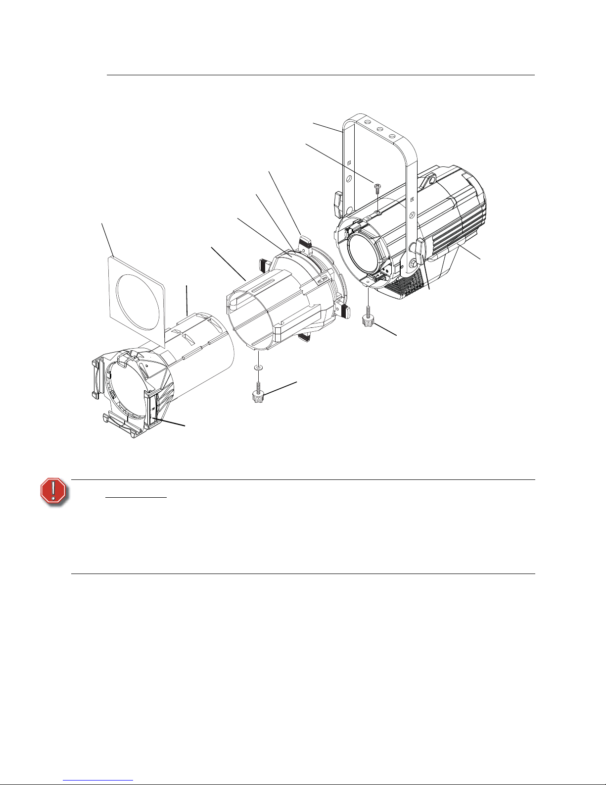
Basic Assembly
Figure-1.1 Basic assembly.
Mounting Hardware
A yoke is available for mounting fixtures.
WARNING:
Please note the following safety warnings before use:
Do not mount the fixture on or near combustible surfaces.
Do not operate the fixture without a lens installed.
Always hang the fixture with the color frame retaining clip in the locked
position.
Always use a properly installed safety cable.
Color frame holder
Beam focus knob
Color frame
Lens tube
Shutter barrel
assembly
Barrel rotation knob
Yoke locking knob
Light engine
body
Yoke
Retainer bolt
Shutters
Pattern holder slot
Drop-in iris slot
NOTE: Safety cable is not included.
Page 23
1 Installation and User Interface Overview 18
Install Lens Tube
Any of the ETC Source Four lens tubes can be installed into the shutter barrel of the Source
Four LED Profile. For better results, use one of the preferred lens tubes listed below.
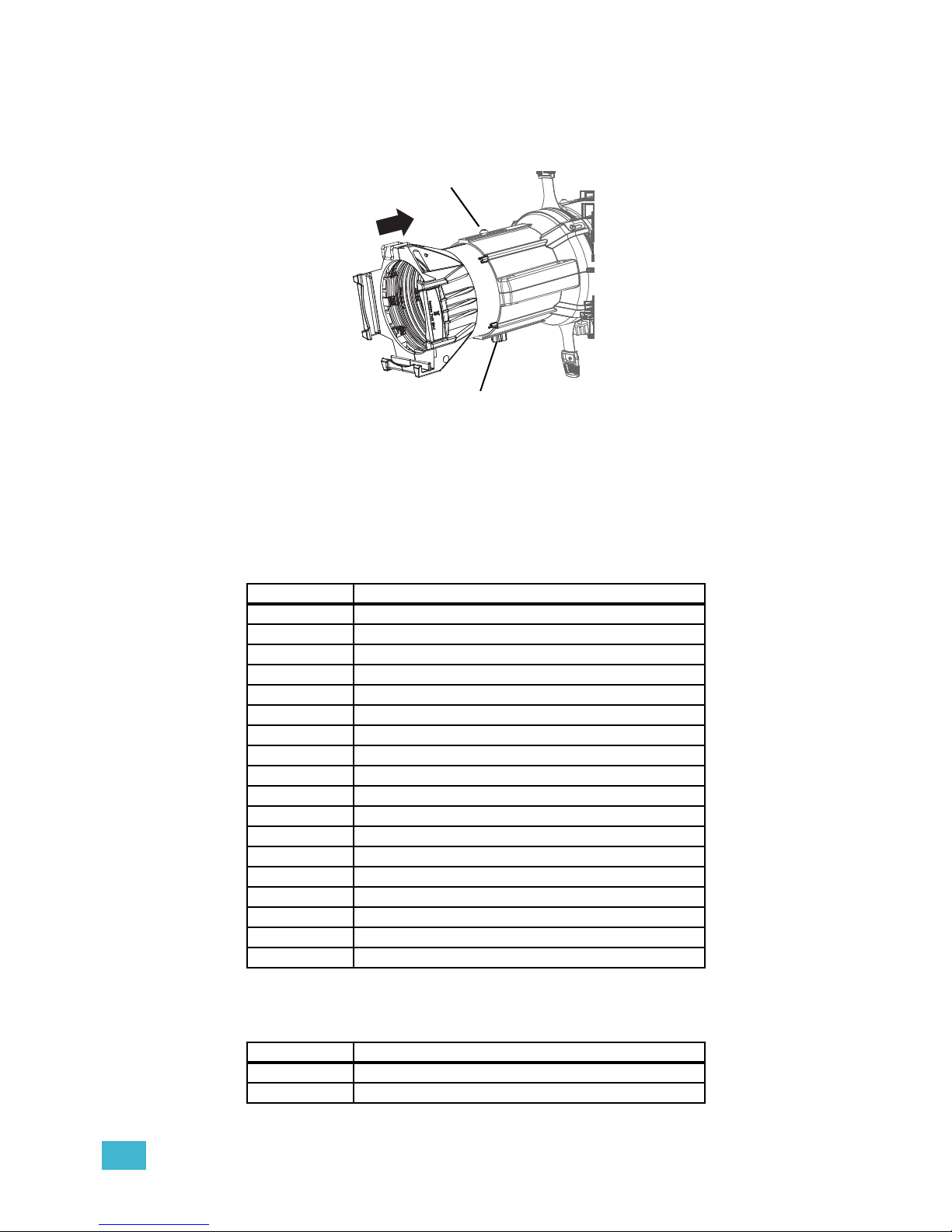
Figure-1.2 Secure lens tube with zoom knob and Phillips screw.
Step 1: Slide the lens tube into shutter barrel.
Step 2: Install the lens zoom knob.
Step 3: Install the Phillips screw in the top of the lens barrel.
Preferred Lensing Options
Fixed Beam Lenses
Zoom Lens Assemblies
Use with light engine body without the shutter barrel.
Model Description
LED50LT LED specific 50° EDLT with lenses installed
LED50LT-1 LED specific 50° EDLT (white) with lenses installed
436EDLT 36° EDLT w/lens installed
436EDLT-1 36° EDLT (white) w/lens installed
426EDLT 26° EDLT w/lens installed
426EDLT-1 26° EDLT (white) w/lens installed
419EDLT 19° EDLT w/lens installed
419EDLT-1 19° EDLT (white) w/lens installed
490LT 90° w/lens installed
490LT-1 90° (white) w/lens installed
470LT 70° w/lens installed
470LT-1 70° (white) w/lens installed
414LT 14° w/lens installed
414LT-1 14° (white) w/lens installed
410LT 10° w/lens installed
410LT-1 10° (white) w/lens installed
405LT 5° w/lens installed
405LT-1 5° (white) w/lens installed
Model Description
41530LT Source Four 15-30 Zoom lens assembly
42550LT Source Four 25-50 Zoom lens assembly
Beam focus knob
Phillips screw
Page 24
19 Source Four LED Profile v1.5.0 User Manual
Aim Adjustments
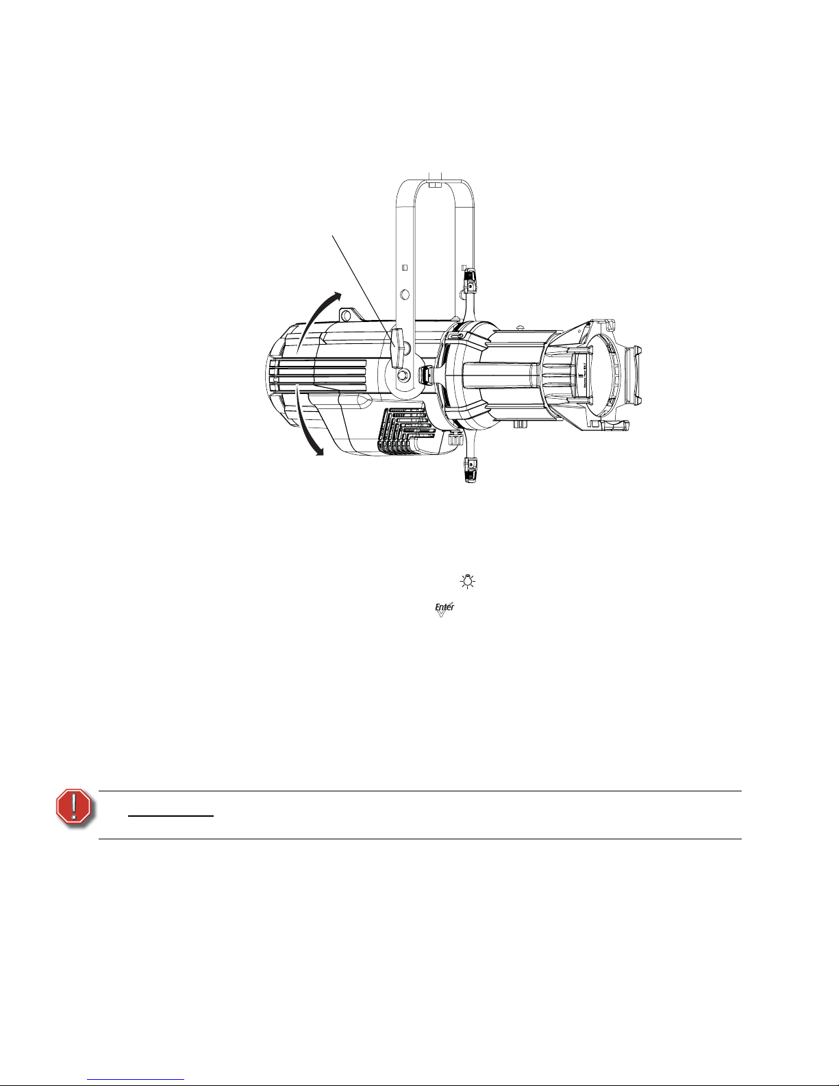
The fixture can be tilted up and down to aim the light where it is needed. The adjustment is
the same for the yoke or floor stand. To assist aiming the fixture, you can turn it on without
having to be connected to DMX control or enabling a preset. For more information, see
Focus, page 57.
Figure-1.3 Tilting the Fixture on the Yoke.
Turning the Fixture On
Step 1: Apply power to the fixture.
Step 2: On the back of the fixture press [].
Step 3: With Focus selected, press [].
Adjusting the Tilt
Step 1: Loosen the yoke locking knobs. Do not remove them.
Step 2: Tilt the fixture to the desired position.
Step 3: Tighten the yoke locking knobs to secure in position.
Adjusting the Pan
The pan is adjusted at the hanging clamp. Please consult the clamp manufacturer’s
documentation for instructions on loosening and rotating the yoke at the clamp.
WARNING:
A safety cable (or other approved safety device) must be securely attached to
the safety cable loop before loosening the clamp.
Yoke locking
knob
Page 25
1 Installation and User Interface Overview 20
Focusing the Beam
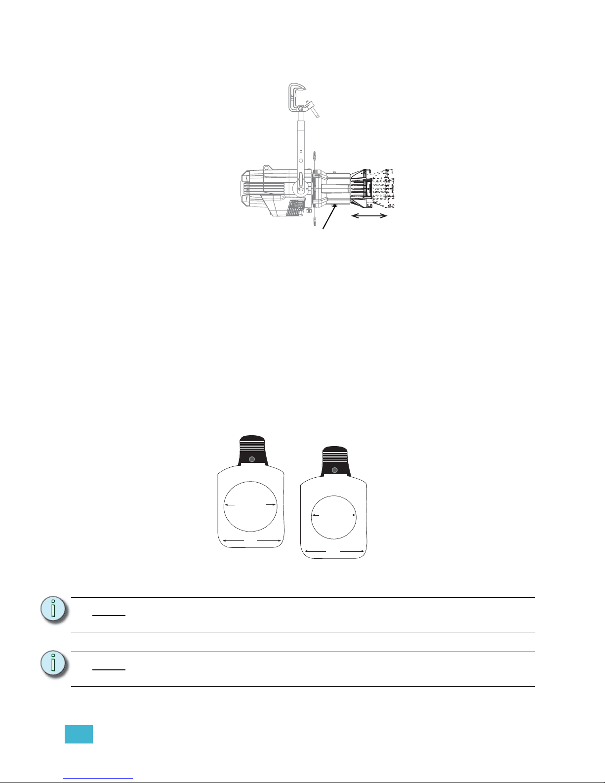
Figure-1.4 Focusing the beam.
Step 1: Loosen the beam focus knob located under the barrel as shown in Figure-1.4.
Step 2: Slide the lens tube forward or backward to achieve the desired beam edge.
Step 3: Once the fixture is focused, tighten the beam focus knob.
Shaping the Beam
The beam can be shaped using the shutters (see Figure-1.1), a pattern, an optional drop-in iris, or
by rotating the barrel.
Pattern Projection
The pattern holder slot is on the top side of the barrel and in front of the shutters. It accommodates
A-size, B-size, and glass pattern holders.
Figure-1.5 Pattern holders.
Note:
Pattern projections generally look best when used with the included Soft Focus
diffuser.
Note:
Because the Source Four aperture is 3 inches wide, ETC recommends using A-size
patterns for maximum pattern effectiveness.
Beam focus knob
3.12" Diameter
3.70"
2.75" Diameter
3.70"
A-Size Pattern holder: holds 3”
diameter patterns
B-Size Pattern holder:
holds 2.5” and 2.75”
diameter patterns
Page 26
21 Source Four LED Profile v1.5.0 User Manual
Soft Focus Diffuser
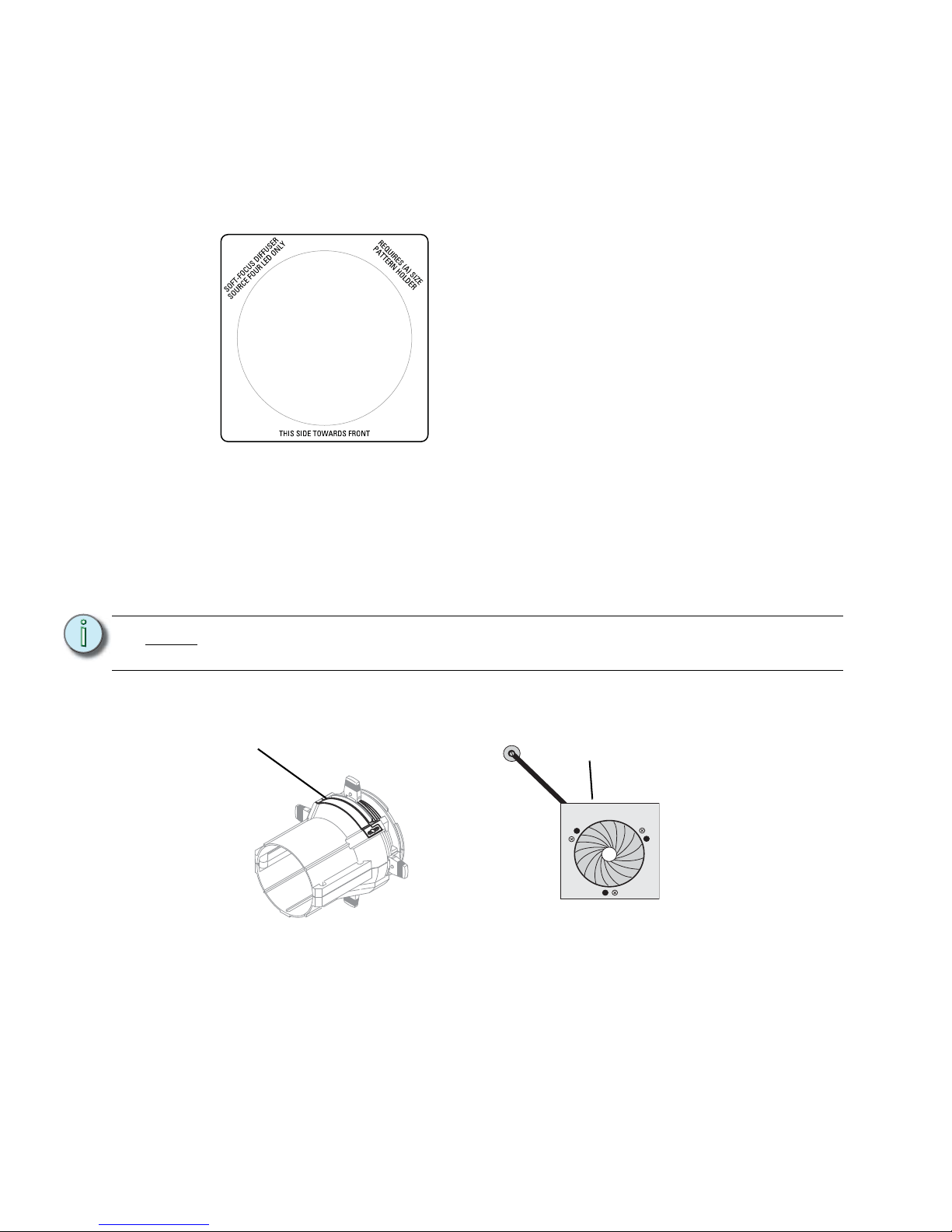
To clean up edge effects, use the soft focus diffuser in the A-size pattern holder. If
combining the diffuser with a pattern, put the diffuser behind the pattern. The soft focus
diffuser allows you to maintain sharp focus of the pattern while eliminating edge effects. The
diffuser is intended for Source Four LED fixtures only.
A permanent install kit is available.
Figure-1.6 Soft Focus diffuser.
Step 1: Install the diffuser into an A-Sized Pattern holder.
Step 2: Install a pattern in front of the diffuser, if needed.
Step 3: Insert the pattern holder and diffuser into the Pattern holder slot, making sure the
writing on the diffuser faces the front of the fixture.
Also see Smooth Wash Diffuser, page 36.
Accessory Slot
Figure-1.7 Accessory slot
The accessory slot is located on the top of the shutter barrel and in front of the pattern holder slot.
It accommodates either a drop-in iris or a motorized pattern device. When the slot is not in use, a
small sheet metal cover secured with two Phillips screws prevents light leakage.
Note:
Enhanced Definition Lens Tubes (EDLT) are highly recommend for use with Source
Four LED series luminaires to provide a crisper pattern projection.
Accessory slot
Iris
Page 27
1 Installation and User Interface Overview 22
Step 1: Use a Phillips screwdriver to loosen the screws on the drop-in iris slot cover. Do
not remove screws.
Step 2: Slide the cover completely forward to expose the slot.
Step 3: Insert the iris or motorized pattern device. For an iris, install the flat side toward
the shutters and make sure the iris handle extends from the slot.
Step 4: Slide the slot cover back toward the shutters until it meets the iris handle. Leave
enough space to move the iris handle.
Step 5: Secure the accessory slot cover by tightening the screws.
Rotating the Shutter Barrel Assembly
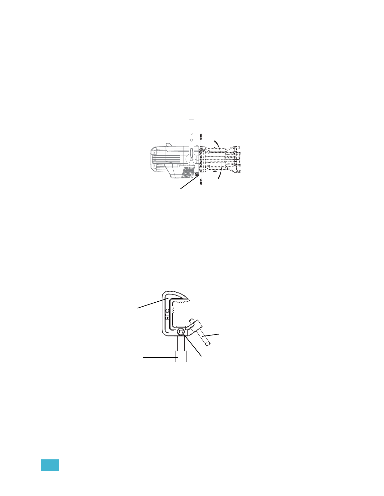
Figure-1.8 Rotating the shutter barrel assembly
Step 1: Loosen the shutter barrel rotation knob directly behind the shutters on the
underside of the reflector housing. Do not remove the barrel rotation knob.
Step 2: Rotate the shutter barrel to the desired position (up to 25° in either direction from
the centered position).
Step 3: Once the shutter barrel is positioned, tighten it’s rotation knob to lock it in place.
Adjusting the C-clamp For North America
Figure-1.9 Adjusting the C-clamp.
The C-clamp attaches the fixture to the mounting pipe and allows fixture adjustments when
mounted.
Barrel rotation knob
C-clamp
Pipe bolt
Pan screw
Yoke bolt and
lockwasher
Page 28

23 Source Four LED Profile v1.5.0 User Manual
Step 1: Secure the C-clamp to the yoke with the provided yoke bolt and lock washer.
Step 2: Place the C-clamp on the mounting pipe and secure by tightening the pipe bolt.
Step 3: Loosen the C-clamp pan screw and rotate the yoke to the desired position.
Step 4: Retighten the pan screw to lock the fixture.
CAUTION:
Tighten C-clamp pipe bolt to 15-20 ft./lbs. (approximately finger tight plus up to
one-quarter turn). Do not exceed 25 ft./lbs. Do not use excessive force.
Tighten the yoke pivot bolt to 5-10 ft./lbs. (approximately finger tight plus up to
one-eighth turn). Do not exceed 15 ft./lbs. Do not use excessive force.
Page 29
1 Installation and User Interface Overview 24
Adjusting the Yoke Position
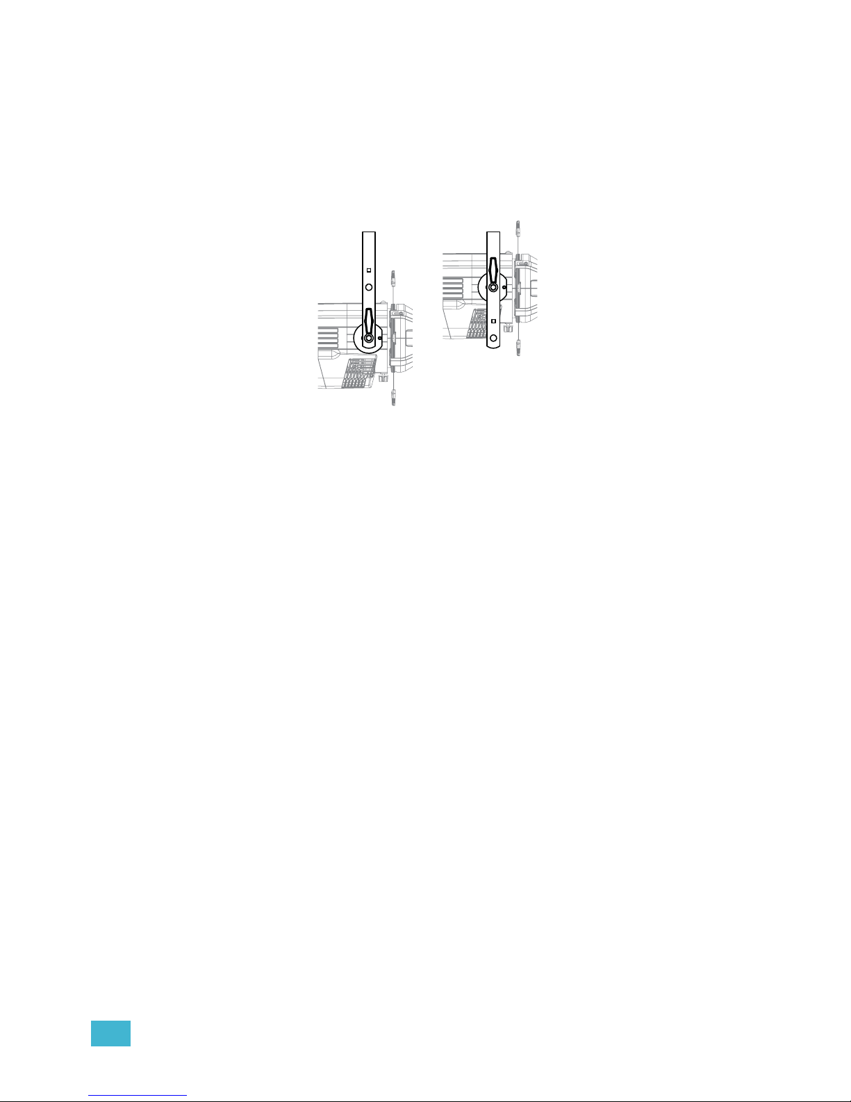
The Source Four provides multi-positioning capabilities within its yoke for overall fixture height and
angle.
Setting the Fixture Height Within the Yoke
The Source Four has a two-position yoke for modifying the overall mounting height.
.
Figure-1.10 Adjusting the yoke position.
To change the fixture yoke position:
Step 5: Remove the yoke locking knobs, washers, and hex bolts from either side of the
fixture.
Step 6: Raise or lower the fixture to the desired position within the yoke.
Step 7: Reinstall the yoke’s hex bolts, washers, and locking knobs.
Step 8: Tighten the yoke knobs to secure in position.
Low clearance position
General use position
Page 30
25 Source Four LED Profile v1.5.0 User Manual
Installation Clearances
Cooling and Duty Cycle
Desire series fixtures are fan cooled and can operate all channels at full power continuously
in ambient temperatures up to 40°C (104°F).
If ambient conditions exceed 40°C (104°F) or fail to allow sufficient airflow, over a long
period of time, the fixtures may shut down and remain off until they return to a safe
operating temperature. The fixtures provide two methods to indicate over temperature that
can be set up on the Local Settings menu. The over temperature indicators are:
Visible
The LED array glows in a dull, low intensity with only some emitters illuminated, the LCD
backlight is turned on, the LCD displays Overtemp Activated, and the Error Indicator light
turns on.
Dark
The LED array turns off and the LCD displays Overtemp Activated. The LCD backlight is
not turned on.
LED life is adversely affected by high-temperature operation. When operating under
elevated ambient temperatures, avoid turning all channels to 100% for extended periods,
such as channel checks or focusing.
CAUTION:
Duty Cycle
Operating the fixtures in higher ambient temperatures or low-airflow situations may
cause the power supply to shut down. Following a cool-down period, the power
supply will automatically reset and the fixture will return to operation.
It is good practice to power down any device with on-board electronics to limit
unnecessary wear on the devices and eliminate residual use of electricity. When not
in use, Desire series fixtures should be powered down by disconnecting from power
either at the breaker or by unplugging.
Page 31
1 Installation and User Interface Overview 26
Dimensions and Hanging Clearances
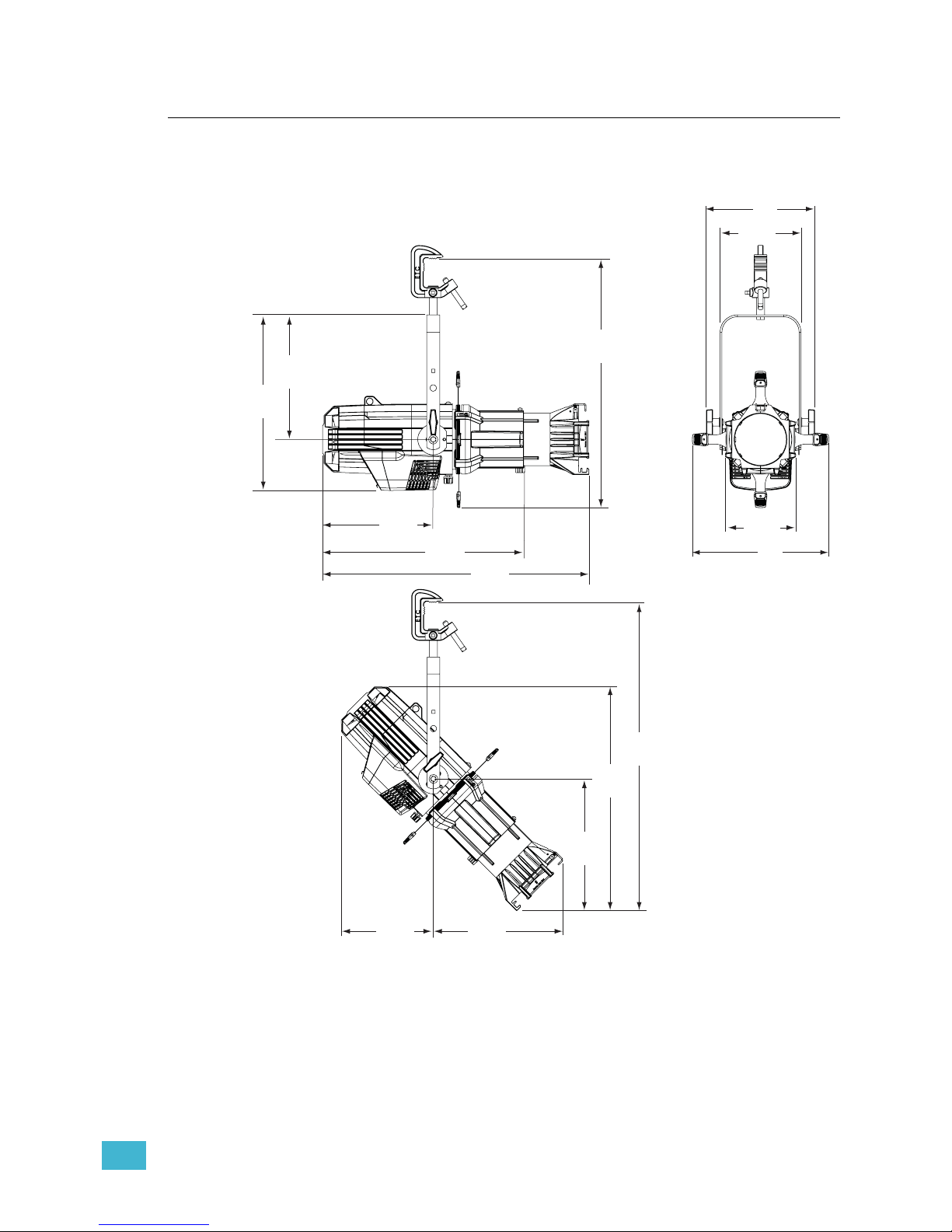
Use the following dimensions to allow proper clearances around the fixture. Allow additional
space for cables.
Figure-1.11 Dimensions with typical 19°, 26° or 36° lens tube fully extended. Other lens tubes
available, but not shown.
6.9”
174mm
12.1”
308mm
17.1”
434mm
24.2”
615mm
13.3”
338mm
7.9”
200mm
10.6”
268mm
10.8”
274mm
25.9”
659mm
30.7”
779mm
22.3”
566mm
13.1”
333mm
9.2”
233mm
12.9”
328mm
19.56”
497mm
Page 32
27 Source Four LED Profile v1.5.0 User Manual
Safety Cable
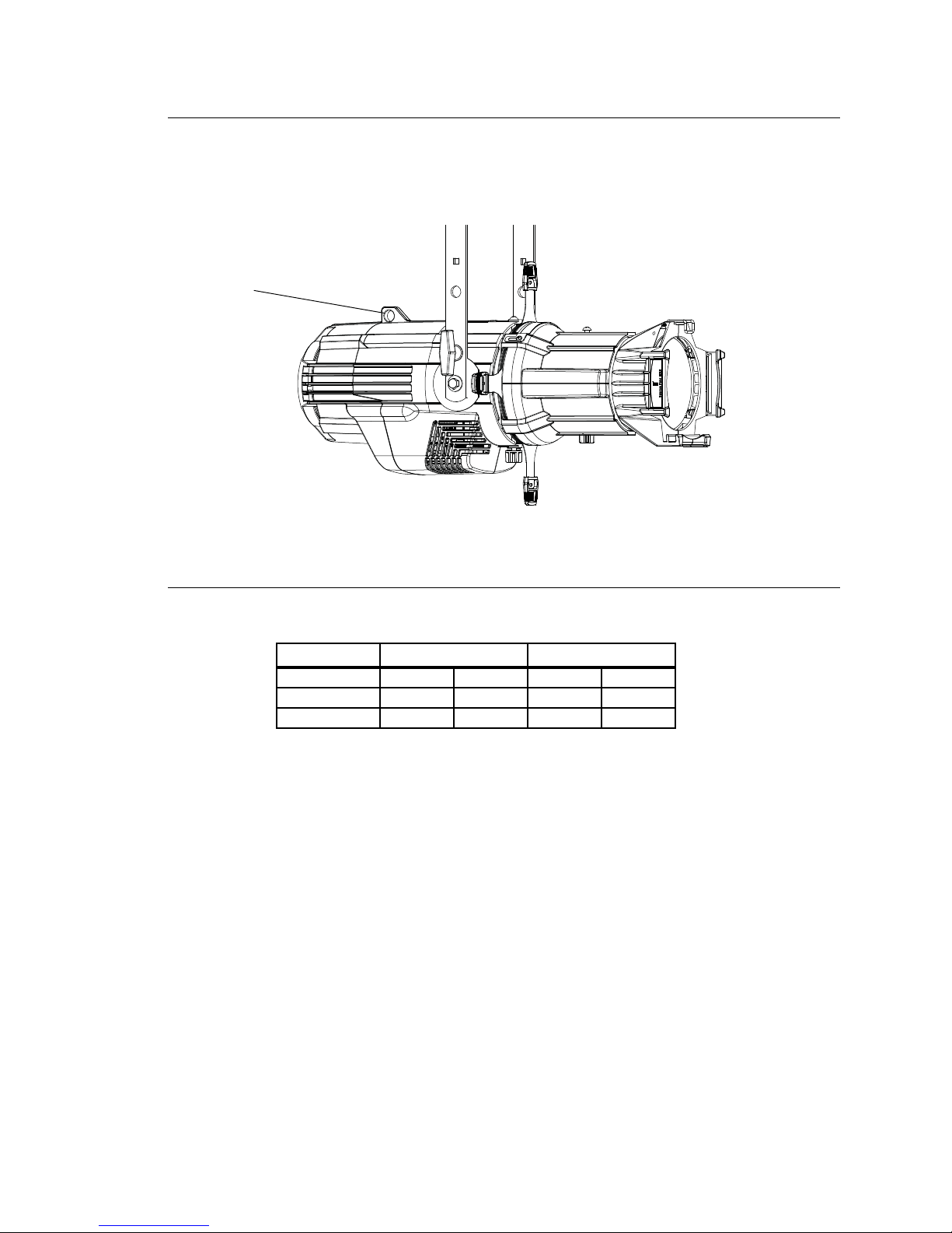
A safety cable (or other approved safety device) should be attached to the fixture housing
and wrapped around the hanging structure (pipe). An appropriate attachment loop is
provided on the protruding tab of the fixture housing. Take care to leave as little slack as
possible in the safety cable to avoid the cable catching the yoke of the fixture.
Figure-1.12 Safety Cable Loop on Fixture Housing.
Fixture Weight
Total weight depends on how the individual fixture is configured.
Model
Weight
a
a) Does not include mounting hardware.
Shipping Weight
Lbs.Kg.Lbs.Kg.
With barrel 18.3 8.3 28 12.7
Without barrel 14.3 6.5 23 10.4
Safety cable
loop
Page 33
1 Installation and User Interface Overview 28
Power and Data Cabling Requirements
Power
The Desire series fixture operates on AC power, 100 to 240VAC/50-60Hz. The fixture must
be connected to a non-dimmable power source in order to avoid damage to its internal
power supply and other electrical components.
Data
The Desire series fixtures operate on a DMX control signal or as standalone fixtures. The
fixture is supplied with a 5-pin XLR DMX input connector and a 5-pin DMX Thru connector.
DMX cables should be acceptable for DMX data transmission (not microphone cable) and
should follow the standard pinout. The optional secondary data pair is not used by the
Desire series fixtures. The maximum DMX data run from any DMX source to the last fixture
in a chain is 1000 feet (300m). Desire series fixtures are self-terminated.
See DMX Profile, page 30 for additional information on DMX addressing of Source Four
LED series fixtures.
WARNING:
The fixture must be connected to a non-dimmable power source in order to
avoid damage to its internal power supply and other electrical components.
Dimming will damage the fixture and void the warranty.
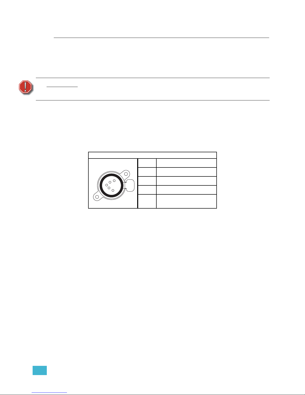
DMX512 pinout for five-pin XLR female
1 Common (Shield)
2 Data –
3 Data +
4 not connected
5 not connected
Push
1
2
3
4
5
Page 34
29 Source Four LED Profile v1.5.0 User Manual
Connections
All connections and user controls are located on the back of the fixture.
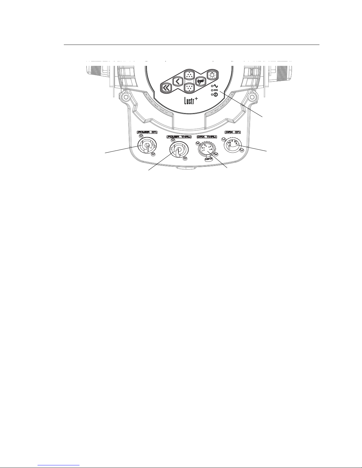
Figure-1.13 Power and DMX Connections on Back of Fixture.
Connect AC input power and DMX data cables to the appropriate ports. Connect the
incoming DMX data cable to the DMX Input connector. If you are daisy-chaining the data
to other fixtures or DMX-controlled devices, connect the next DMX cable to the DMX Thru
connector. Up to 32 fixtures can be connected together into a data daisy-chain.
For information about the user interface, refer to User Interface Overview, page 39.
Source Four LED Series Connections
AC cable
Connect:
Align and insert the power connector. Twist the connector clockwise until it locks into place.
Disconnect:
Slide back the locking tab to unlock, twist the connector counterclockwise, and then pull and
disconnect the power connector.
DMX cable
Connect:
Align and insert the DMX connector.
Disconnect:
Press the release button on the connector or on the fixture and pull the connector out.
Indicator Lights
The indicator lights show the status of power input (blue), DMX input (green) and fixture
errors (red). When the DMX signal is lost, the green indicator flashes.
If the fixture status indicator is configured to Off, the indicator lights will not illuminate. For
more information, see Local Settings, page 73.
Power In
Power Thru
DMX In
DMX Thru
Status indicators
Page 35
1 Installation and User Interface Overview 30
DMX Profile
Addressing
Addresses must be set between 1 and 510.
Each Source Four LED series fixture must be considered a separate DMX device for
the purpose of DMX line-loading calculations.
DMX line-loading practice dictates that no more than 32 devices can be daisy-chained
together. Consequently, no combination of Source Four LED series fixtures totaling more
than 32 DMX devices should be configured in one DMX line. For runs of fixtures totaling
more than 32 DMX devices, split the DMX runs by using a DMX splitter.
Profiles
Source Four LED series fixtures occupy 1 to 15 DMX channels depending on the profile
and which features are turned on. The tables below describe the order and function of each
channel.
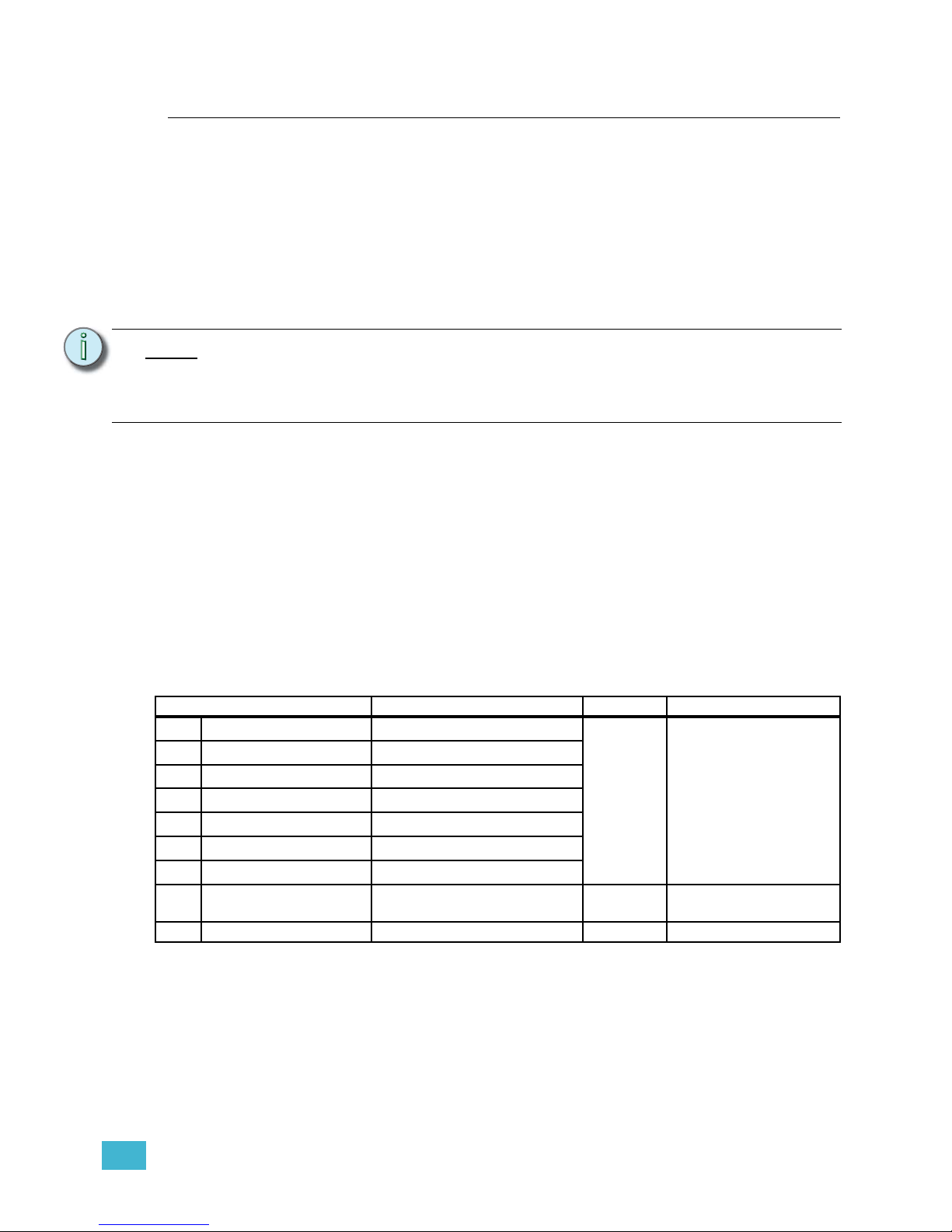
Lustr+ and Studio HD Profile
Direct Control
Direct Control uses one DMX channel per individual color within the LED array for a total of
seven color channels, arranged according to the Color Mixes table. Each controls the
intensity of the color from 0 to 100%. An additional, 8th DMX channel is used as a master
intensity fader for controlling the brightness of the overall fixture. Channel 9 is for strobe
when enabled.
Note:
Depending on the selected fixture profile and activated features, a fixture with a
starting address higher than 499 may not have control of all parameters, even though
the highest address shown on the user interface is 512.
Addressing is not required for standalone operation.
Data Channel Control Value Function
1 Fixture address
Color 1
a
a) See Color Mixes, page 31.
0 to 255
Color intensity 0 to100%
2 Fixture address + 1
Color 2
a
3 Fixture address + 2
Color 3
a
4 Fixture address + 3
Color 4
a
5 Fixture address + 4
Color 5
a
6 Fixture address + 5
Color 6
a
7 Fixture address + 6
Color 7
a
8 Fixture address + 7 Intensity
Overall intensity 0 to
100%
9 Fixture address + 8 Strobe Variable strobe control
Page 36
31 Source Four LED Profile v1.5.0 User Manual
Color Mixes
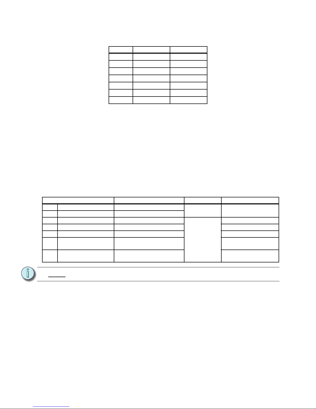
The following table shows the color mixes for the fixture.
Terminology:
• White Point - The color temperature of a white light when saturation is at zero%.
• Tint - The balance between green and magenta within a fixture.
HSI and HSIC:
The HSI profile (Hue, Saturation, Intensity) uses four channels of DMX input, corresponding
to 16-bit hue (two channels: coarse and fine), saturation, and intensity. The HSI profile
makes Source Four LED series fixtures compatible with conventional HSI console profiles
while capitalizing on fixtures' expanded color capabilities. Channel 5 is for Strobe, when
enabled. Also see Color Matching, page 33.
The HSIC profile (Hue, Saturation, Intensity, Color Temperature (White Point)) is similar to
HSI, except that it uses an additional sixth channel to control the color temperature of the
white point. The Red Shift function is automatically disabled in the HSIC profile.
Color Lustr+ Studio HD
1Red Red
2 White Red Orange
3 Amber Mint
4 Green Blue
5Cyan Indigo
6Blue —
7Indigo —
Data Channel Control Value Function
1 Fixture address Hue coarse
0 to 65535
Hue 0
2 Fixture address + 1 Hue fine
3 Fixture address + 2 Saturation
0 to 255
Saturation 0 to 100%
4 Fixture address + 3 Intensity Intensity 0 to 100%
5 Fixture address + 4 Strobe Variable strobe control
6 Fixture address + 5 Fan control
Force fan on various
speeds
7 Fixture address + 6 White point
Color temperature 2700 to
6500K
Note:
The HSI profile is optimized for maximum brightness at all settings.
Page 37
1 Installation and User Interface Overview 32
RGB
Effectively addresses all seven colors via three channels of control. The RGB profile
produces medium-quality color crossfades. It makes the Source Four LED series fixtures
compatible with conventional RGB console profiles while maintaining enhanced color
production from the fixture. Also see Color Matching, page 33
.
Studio
The fixture produces only white-type light, which is adjustable from 2700 to 6500K. The
Studio profile uses three DMX channels to control Intensity, white point, and tint. Tint is
adjustable without affecting the white point. All three control parameters are adjustable via
DMX as well as onboard with instant access via UI buttons.
For more information, see Studio Settings, page 77. Also see Color Matching, page 33.
Data Channel Control Value Function
1 Fixture address Red
0 to 255
Intensity 0 to 100%2 Fixture address + 1 Green
3 Fixture address + 2 Blue
4 Fixture address + 3 — — —
5 Fixture address + 4 Strobe
0 to 255
Variable strobe control
6 Fixture address + 5 Fan control
Force fan on various
speeds
Note:
The RGB profile is optimized for maximum brightness at all settings. Occasionally
small changes in RGB values may produce unexpected jumps in brightness.
Shifts in brightness may be perceived during color crossfades in cues and presets.
Data Channel Control Value Function
1 Fixture address Intensity
0 to 255
Intensity 0 to 100%
2 Fixture address + 1 White point: 2700 to 6500K
0 = 3200K
1 to 254 = 2700K to 6500K
255 = 5600K
3 Fixture address + 2 Tint
0 = neutral white
1 to 127 = full plus-green
to neutral white
128 = neutral white
129 to 255 = neutral white
to full minus-green (full
magenta)
4 Fixture address + 3 — — —
5 Fixture address + 4 Strobe
0 to 255
Variable strobe control
6 Fixture address + 5 Fan control
Force fan on various
speeds
Page 38
33 Source Four LED Profile v1.5.0 User Manual
Strobe
In most profiles, strobe is assigned to channel 5. It adds another channel to any of the DMX
profiles. Under the Advanced Settings menu, the strobe function may be disabled and the
additional channel for strobe will not be used by the fixture. With strobe at either DMX value
0 or 255, the fixture output is constantly on. At DMX 1, the fixture strobes slowly and
increases in speed toward DMX 254.
Plus 7
Plus 7 adds precision color-control channels to the HSI, HSIC, RGB, and Studio profiles.
For example, HSI with Plus 7 enabled becomes a 15-channel profile. Placing channel 7 at
a value over 51% activates the 15-channel profile within the fixture. The desired color and
intensity is achieved by using the HSI or RGB channels as a starting point. Channels 8 to
14 represent the native LED colors of the fixture and allow you to adjust each color up or
down in order to fine-tune the overall color output.
Color Matching
The color output of all Source Four LED series fixtures is calibrated at the factory. When
operating in the RGB, HSI, HSIC, or Studio profile, each fixture makes accommodations for
the specific LEDs in its array and produces output that is consistent with other fixtures,
whether or not they utilize LEDs from the same production batch. Operating in the Direct
Control profile or with Plus 7 settings adjustments bypasses this calibration and multiple
fixtures may produce slightly different outputs when controlled as a group.
Note:
Depending on the initial color mix, some LED colors may begin at full intensity.
Moving the individual control channels for these colors from 128 to 255 will produce
no effective change from the initial color mix. Conversely, some LED colors may
begin at zero intensity, and moving individual control channels from 128 to 0 will
produce no change.
Data Channel Control Value Function
8 Fixture address + 7 Plus 7 control
0 to 129 = Plus 7 disabled
130 to 255 = Plus 7 enabled
Disable or enable Plus 7
control
9 Fixture address + 8
Color 1
a
a) See Color Mixes, page 31.
128 = No change from initial color
mix
129-255 = Increase from starting
value to full intensity
127-0 = Decrease from starting
value to zero intensity
Alter the individual LED
colors within the array to a
maximum of full intensity
or a minimum of zero
intensity.
10 Fixture address + 9
Color 2
a
11 Fixture address + 10
Color 3
a
12 Fixture address + 12
Color 4
a
13 Fixture address + 13
Color 5
a
14 Fixture address + 14
Color 6
a
15 Fixture address + 15
Color 7
a
Page 39
1 Installation and User Interface Overview 34
Daylight and Tungsten Profiles
Direct Control
The first DMX channel always controls Intensity from 0 to 100%.
Fan Control
The Fan setting allows four options: DMX, Slow, Fast, and Automatic.
With Fan set to DMX, an additional channel of DMX control is added to the fixture profile.
This channel immediately follows the channel for Strobe. Control is as follows:
• DMX 0 — Fan turns on and off automatically, as needed for cooling. Fan remains off
when not required by the fixture.
• DMX 1 to 254 — Fan is forced on at a continuously variable speed from low to high.
Occasionally, the fan speed may be increased automatically by the fixture for additional
cooling power when required.
• DMX 255 — Fan is forced on at its highest, loudest speed for maximum consistency of
noise produced by the fixture.
When Fan is set to Slow, Fast, or Automatic, there is not a channel designated for control
within the DMX profile. At Slow and Fast settings, the fan operates whenever the fixture is
powered on, independent of other fixture settings or control.
• Slow — Fan runs continuously at a low-noise speed. When deemed necessary by the
fixture, the fan speed may be increased automatically for additional cooling power.
• Fast — Fan runs continuously at its highest and loudest speed, and never increases
automatically.
• Automatic — Fan operation is intermittent and based on the fixture's internally
calculated cooling requirements.
Data Channel Control Value Function
1 Fixture address Intensity
0 to 255
Intensity 0 to 100%
2 Fixture address + 1 Strobe Variable strobe control
3 Fixture address + 2 Fan control
Force fan on at various
speeds
Page 40
35 Source Four LED Profile v1.5.0 User Manual
DMX Footprints and Channel Mapping
Tungsten and Daylight
Lustr+ and Studio HD
* When this feature is enabled.
Channel Control
1 Intensity
2
Strobe
*
3
Fan control
*
Channel HSI HSIC RGB Studio Direct
1 Hue Hue Red Intensity Color 1
2 Hue fine Hue fine Green Color temp Color 2
3 Saturation Saturation Blue Tint Color 3
4 Intensity Intensity N/A N/A Color 4
5 Strobe* Strobe* Strobe* Strobe* Color 5
6
Fan control
*
Fan control
*
Fan control
*
Fan control
*
Color 6
7 N/A Color temp N/A N/A Color 7
8
Plus7 on/off
*
Plus7 on/off
*
Plus7 on/off
*
Plus7 on/off
*
Intensity
9
Plus7 - (1)
*
Plus7 - (1)
*
Plus7 - (1)
*
Plus7 - (1)
*
Strobe
*
10
Plus7 - (2)
*
Plus7 - (2)
*
Plus7 - (2)
*
Plus7 - (2)
*
Fan control
*
11
Plus7 - (3)
*
Plus7 - (3)
*
Plus7 - (3)
*
Plus7 - (3)
*
N/A
12
Plus7 - (4)
*
Plus7 - (4)
*
Plus7 - (4)
*
Plus7 - (4)
*
N/A
13
Plus7 - (5)
*
Plus7 - (5)
*
Plus7 - (5)
*
Plus7 - (5)
*
N/A
14
Plus7 - (6)
*
Plus7 - (6)
*
Plus7 - (6)
*
Plus7 - (6)
*
N/A
15
Plus7 - (7)
*
Plus7 - (7)
*
Plus7 - (7)
*
Plus7 - (7)
*
N/A
Page 41
1 Installation and User Interface Overview 36
Installing Accessories
Color Frame Holder
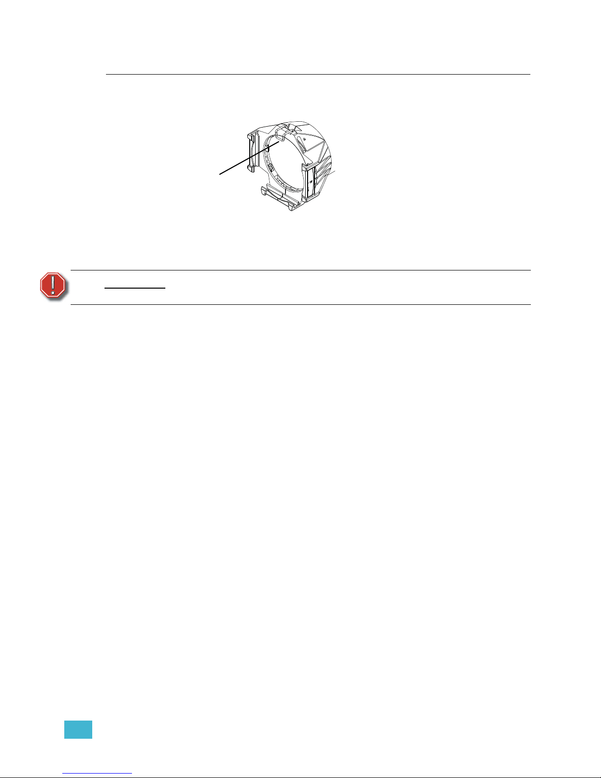
Figure-1.14 Color frame holder and retaining clip.
The gel frame holder is equipped with a spring-loaded retaining clip that prevents gel frames and
accessories from falling out.
Step 1: Release the retaining clip by pushing it sideways while gently pulling backwards.
Step 2: Insert the color frame or other accessory.
Step 3: Lock the retaining clip by pushing sideways while gently pushing forward.
Smooth Wash Diffuser
To reduce edge effects and provide better overlap when using the fixture for wash, use a
smooth wash diffuser. If this diffuser is used, it recommended to not use the soft focus
diffuser in the pattern holder. See Soft Focus Diffuser, page 21.
WARNING:
Make sure all color frames and accessories are locked in position with the
retaining clip before hanging the fixture.
Retaining clip
shown in the
locked position
Page 42

37 Source Four LED Profile v1.5.0 User Manual
Page 43

2 Basic Menu Navigation 38
Chapter 2
Basic Menu Navigation
This chapter contains the following sections:
• User Interface Overview . . . . . . . . . . . . . . . . . . . . . . . . . . . . .39
• LCD . . . . . . . . . . . . . . . . . . . . . . . . . . . . . . . . . . . . . . . . . . . . . .39
• Screen Navigation . . . . . . . . . . . . . . . . . . . . . . . . . . . . . . . . . .41
• Status (Home) Screens . . . . . . . . . . . . . . . . . . . . . . . . . . . . . .42
• Menu Navigation . . . . . . . . . . . . . . . . . . . . . . . . . . . . . . . . . . .43
Page 44
39 Source Four LED Profile v1.5.0 User Manual
User Interface Overview
The Source Four LED series user interface (UI) consists of an LCD and keypad. All of the
basic information is displayed on the LCD and the keypad is used to navigate through the
menus. Use the LCD and keypad to program the fixture for your specific application.
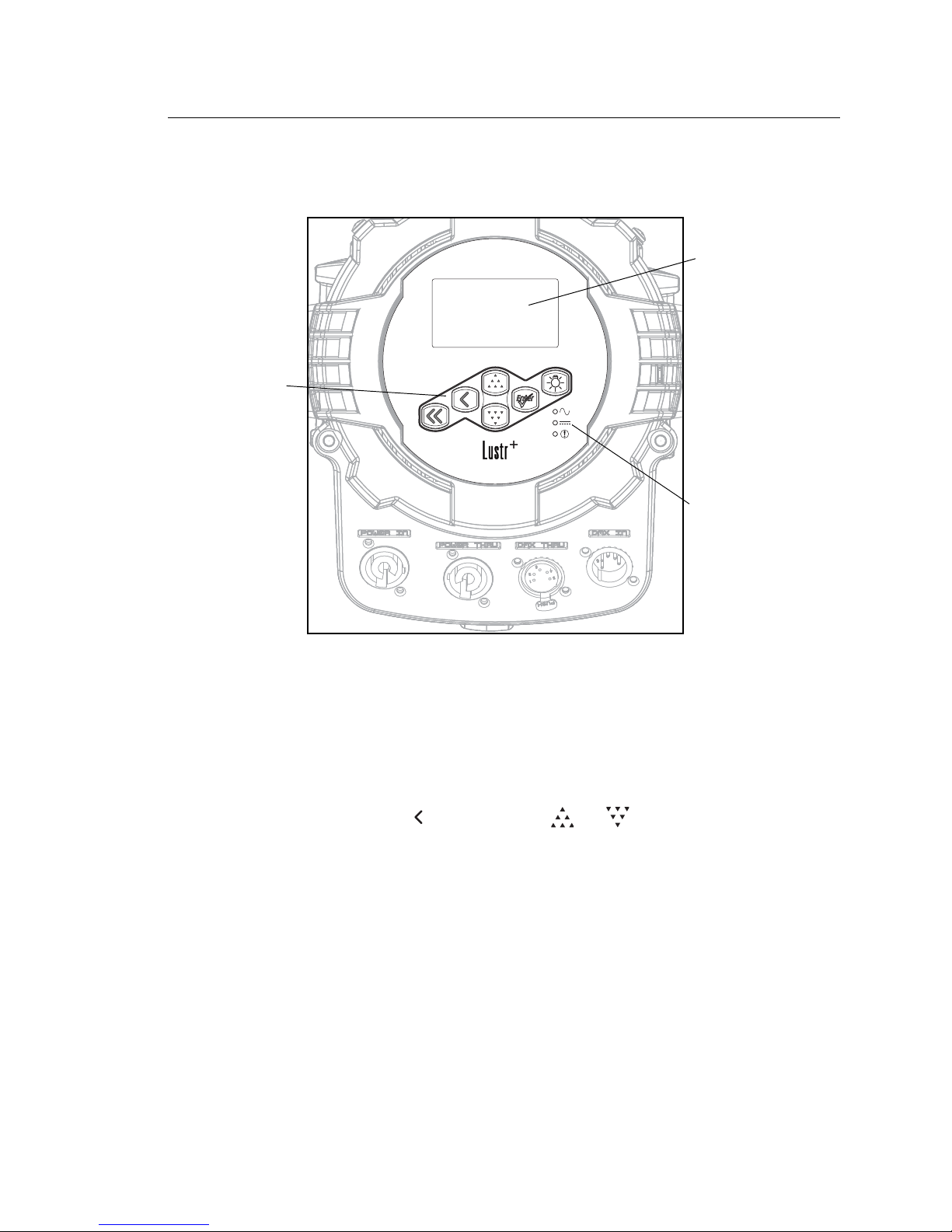
Figure-2.1 User Interface on back of fixture.
LCD
The Source Four LED series fixture features a backlit LCD capable of displaying 8 rows of
text with 21 characters per line. The first row is reserved for the menu title.
To adjust the contrast of the LCD:
Step 1: Press and hold [] and then press [] or [].
Status indicators
LCD
Keypad
Page 45
2 Basic Menu Navigation 40
Keypad
Use the keypad buttons to access and navigate the menus on the LCD.
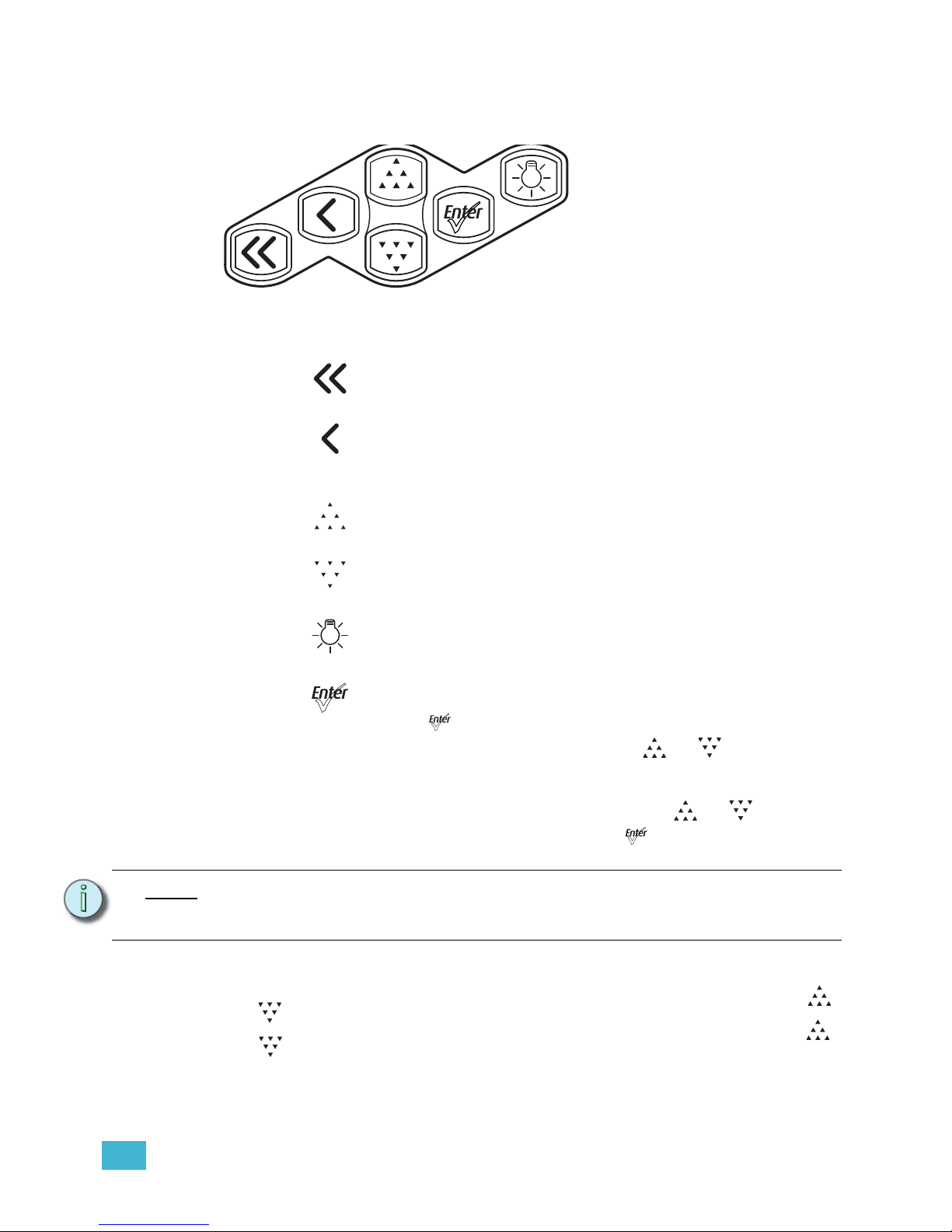
Figure-2.2 Keypad buttons.
Keypad Lockout
The keypad may be locked to prevent unauthorized access to fixture settings. Press []
and [] simultaneously for approximately 3 seconds. A small padlock icon appears in the
corner of the UI screen to indicate that the keypad is locked. To unlock, again press []
and [] simultaneously for approximately 3 seconds. The padlock icon disappears. The
locked or unlocked status of the keypad persists through on/off power cycles. Keypad
lockout does not affect access to fixture settings via RDM.
Home
Opens the home screen.
Back
Cancels the current operation and returns to the previous screen.
Multiple presses of the back button will eventually take you to the
status display.
Up
Increases a value or menu choice by one. Pressing and holding the
push button increases the rate of change.
Down
Decreases a value or menu choice by one. Pressing and holding the
push button increases the rate of change.
Light Bulb
Opens the Presets and Sequences menu.
Enter
• Activates a menu selection or stores a value. For most settings,
push [] repeatedly to scroll through available options while the
setting is highlighted, and then push [] or [] to commit the
change and move to a different setting.
• Certain settings require the selection of a numeric value. Press
Enter once to highlight the number, push [] or [] to reach
the desired value, and then press [] to commit the change.
Note:
When the fixture is in the stand-alone mode of the Studio profile, the functionality of
the buttons changes. For more information, see Operation From Home Status Screen
(Studio Standalone), page 77.
Page 46
41 Source Four LED Profile v1.5.0 User Manual
Status Indicators
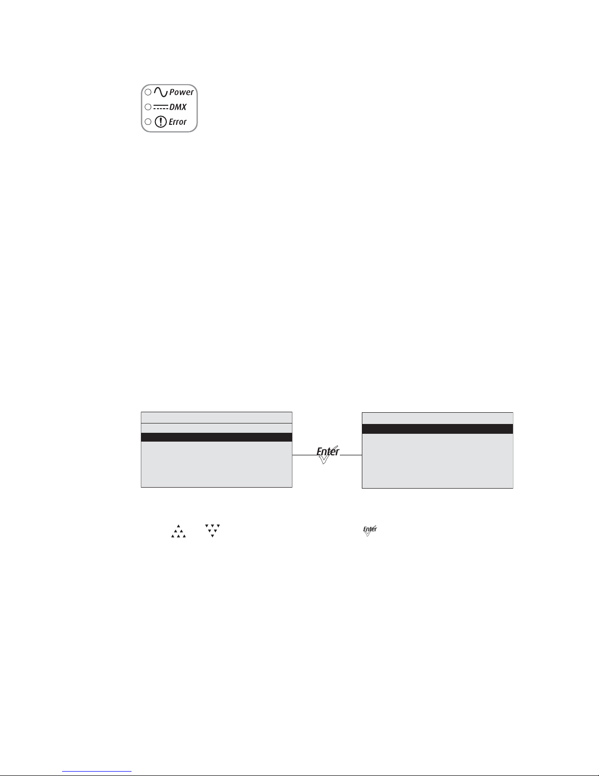
Figure-2.3 Status Indicators on the back of the fixture.
The status indicators are three, small, colored LEDs on the User Interface that indicate the
status of:
• Power — Illuminated blue when AC power is supplied to the fixture.
• DMX — Illuminates green when an active DMX signal is being received by the
fixture.
• Error — Illuminates red only when the fixture is experiencing a data error, high
internal temperature, or other abnormal condition.
Status indicators are on by default. You can turn them off through the Local Settings menu.
For more information, see Local Settings, page 73.
Screen Navigation
When the Source Four LED series fixture is powered up, a splash screen briefly displays,
followed by a status screen.
The menu system and LCD backlight are set, by default, to “sleep” after one minute of
inactivity. Any button press wakes the LCD backlight. You can set the inactivity time on the
Local Settings menu. To “wake up” the display and go to the button’s respective function,
press any keypad button. For example, if you press [Enter], the LCD backlight comes on
and the Main Menu displays. For more information, see Local Settings, page 73.
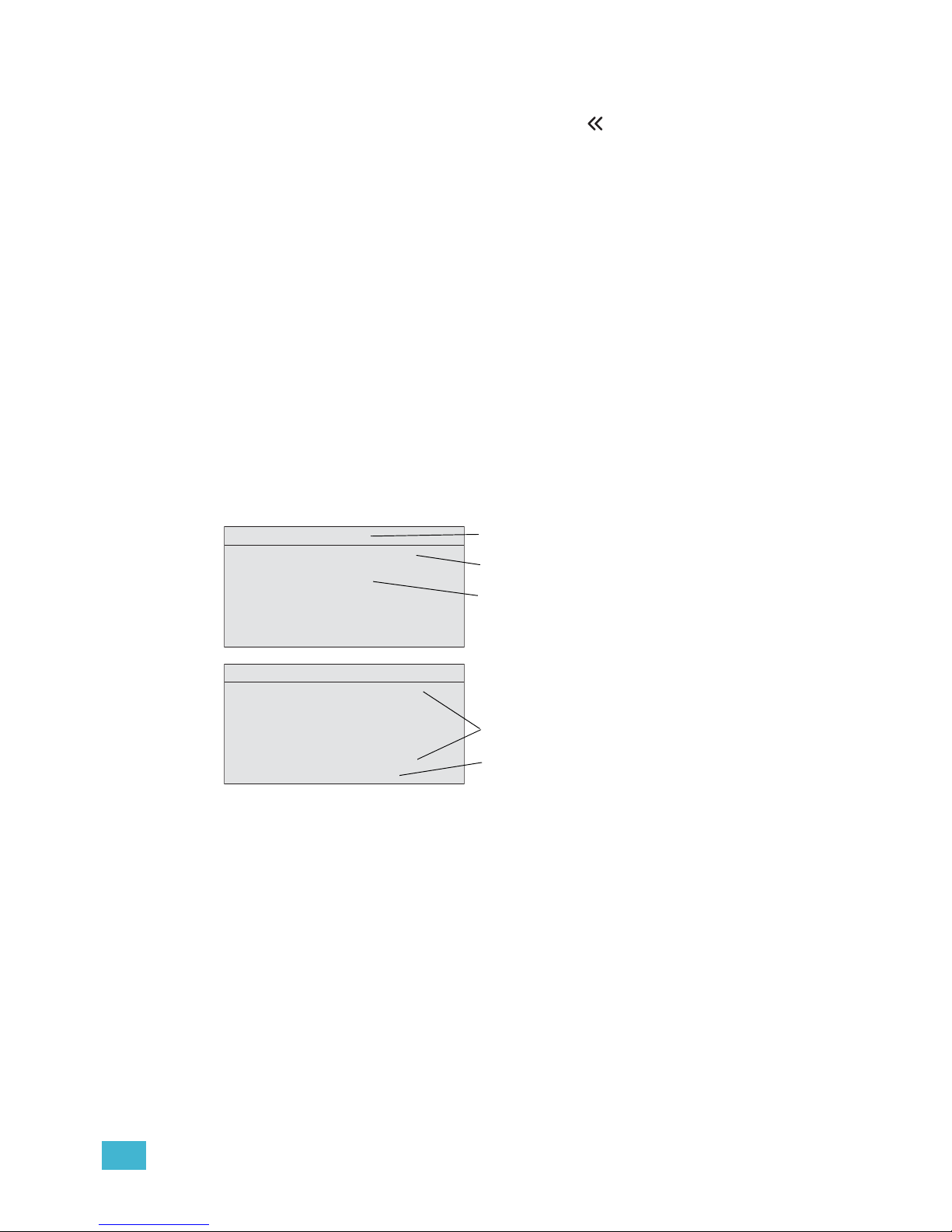
Figure-2.4 Main Menu with Quick Setups selected and the result of pressing enter.
Lustr+ screen shown.
Press [] or [] to highlight a menu item. Press [] to select the item. The asterisk (*)
indicates that the item is currently active.
Quick Setups
*General
Stage
High Impact
Studio
2/15 Hue Fine
XT Arch
Main Menu
DMX Start Address: 001
Quick Setups
Advanced Settings
Page 47
2 Basic Menu Navigation 42
Status (Home) Screens
The status (home) screens display when you press [] or when there is no activity for a
specific time. The home screens display the status of multiple fixture settings. These may
or may not include:
• Quick Setup
• Input settings
• DMX address
• LED settings
• Preset or Sequence that may be active
• Master or Slave status, when applicable
• Diagnostic messages
• DMX signal status
• Software version
Most of the settings can be adjusted either on the home screen or within a short series of
menus. When a quick setup is selected, the settings of the setup are displayed on the home
screen.
For more information about status screens, see Home Screen Displays, page 45.
Figure-2.5 Examples of status screens.
Display Title
A menu’s title appears in the first row of every display for easy navigation.
Input Settings
Displays the parameters for the Quick Setup that is active. For more information, see Home
Screen Displays, page 45.
DMX Address
Indicates the DMX address when the fixture is receiving DMX. For more information, see
DMX Start Address, page 47.
Stage
HSI Reg Incd RS ––
Power Budgeting 75%
001
Error!
11/15 +7 Amber Adj
XT Arch
Master
Step 4: Preset 3
3/15 S a t u r ation
Sequence 5 Active
8Ch Reg Stnd RS Strb
Error!
Overtemp Activated
DMX address
Input settings
System message area
Status bar
Display title
Page 48

43 Source Four LED Profile v1.5.0 User Manual
System Message Area
Displays status messages, which vary depending on the function that is currently active.
Master or Slave
Indicates if the fixture is the master or slave when the a string of fixtures is running together
in standalone operation. For more information, see Master/Slave Operation, page 67.
Sequence
Indicates whether or not a sequence is active and if so, which sequence is active. For more
information, see Presets & Sequences, page 57.
Step
Indicates whether or not a preset is active and if so, which step and preset is active. For
more information, see Presets & Sequences, page 57.
Preset
Indicates which preset is currently active. For more information, see Presets & Sequences,
page 57.
Error
Displays error messages. Refer to Error Messages, page 80 for a complete listing of
possible errors and the actions required to clear them.
Status Bar
Indicates the DMX channels, type, and effect the setup uses.
Menu Navigation
The menu is designed with consistent navigation from the user interface (UI) using the
keypad.
The Main Menu is the root for all menu navigation. When an item is selected from the Main
Menu, a secondary menu displays, which includes multiple functions for selection. Some
secondary menus lead to additional menus. Select a menu item to edit its settings or to
proceed to a deeper menu. Items that may be edited are indicated with descriptive text
followed by a colon (:) and a value.
The keypad is used to edit specific objects on the operation menu, such as DMX address,
Preset and Sequence numbers, fade and delay times, etc. Once an edit has been made,
press [] to accept the selection.
Use [] to navigate to the next object for action or edit. To return to the previous
operation, press []. Continue pressing [] to return to the menu list and then the Main
Menu.
[] may also be used with any Yes or No dialog box. Pressing [] is the same as
selecting No.
Page 49

3 Operation 44
Chapter 3
Operation
This chapter contains the following sections:
• Home Screen Displays . . . . . . . . . . . . . . . . . . . . . . . . . . . . . .45
• Main Menu . . . . . . . . . . . . . . . . . . . . . . . . . . . . . . . . . . . . . . . .47
• Advanced Menu . . . . . . . . . . . . . . . . . . . . . . . . . . . . . . . . . . . .49
• Studio Settings. . . . . . . . . . . . . . . . . . . . . . . . . . . . . . . . . . . . .77
• Error Messages . . . . . . . . . . . . . . . . . . . . . . . . . . . . . . . . . . . .80
• Software Updates. . . . . . . . . . . . . . . . . . . . . . . . . . . . . . . . . . .81
• Routine Maintenance. . . . . . . . . . . . . . . . . . . . . . . . . . . . . . . .82
Page 50
45 Source Four LED Profile v1.5.0 User Manual
Home Screen Displays
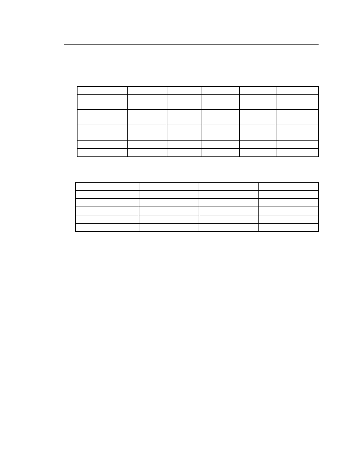
Depending on the fixture settings, the following are displayed in the system message area
on the respective home (status) screens.
Lustr+ and Studio HD
Daylight and Tungsten
Profile Lustr+ and Studio HD
The control profile defines the number and control parameter assignments of input
channels for intensity and color-control. For more information, see Profiles, page 30.
Profile (Daylight and Tungsten)
The control profile for Daylight and Tungsten includes only the Direct or Studio options. The
first channel of DMX control adjusts fixture Intensity from 0 to 100%. For more information,
see Daylight and Tungsten Profiles, page 34.
Output Setting
Output is the way and amount to which the fixture constrains the overall power going to the
LED array, which determines how consistent the fixture’s brightness may be. For more
information, see Output, page 53.
Dimming Curve
Dimming curve is the way that the fixture responds to changes in the control signal for
overall intensity. For more information, see Curve, page 54
Red Shift
Red shift replicates the warming of an incandescent filament’s color temperature change
as it dims. For more information, see Red Shift, page 56.
Strobe
Strobe flashes the output of the LED array. For more information, see Strobe, page 50.
Parameter Stage XT Arch High Impact Studio General
Profile HSI HSI RGB Studio
Direct Control
(Dir)
Output Setting
Regulated
(Reg)
Protected
(Prt)
Boost
(Bst)
Regulated
(Reg)
Regulated
(Reg)
Dimming Curve
Incandescent
(Incd)
Standard
(Stnd)
Quick
(Qik)
Linear
(Lin)
Standard
(Std)
Red Shift (RS) Enabled Disabled Disabled Disabled Disabled
Strobe (Str) On On On On On
Parameter Studio Stage Single Channel
Profile Studio Direct Direct
Output Setting Regulated (Reg) Regulated (Reg) Regulated (Reg)
Dimming Curve Linear (Lin) Incandescent (Incd) Standard (Std)
Strobe (Str) On On Off
Fan Control DMX DMX Automatic (Auto)
Page 51

3 Operation 46
Fan Control
The fan can be forced on via DMX control or by adjusting settings under the Advanced
Settings menu. For more information, see Fan Control, page 34.
Thermal Shutdown Warning
Displayed as OverTemp, it is what the fixture does to visibly warn you that it has become
overheated and has gone into a shut-down status, which is maintained until the fixture
returns to a safe operating temperature. For more information, see OverTemp, page 75.
Data Loss Behavior
What happens to the fixture's output when the external control signal is lost. For more
information, see Data Loss, page 51.
Status Indicators
Status Indicators are on by default. For more information, see Status Indicators, page 74.
Page 52
47 Source Four LED Profile v1.5.0 User Manual
Main Menu
The Main Menu can be accessed at any time while viewing other screens. To access the
Main Menu, press [] and then press [].
DMX Start Address
Use the DMX Start Address to set the DMX address of the fixture. Also see DMX Settings,
page 49.
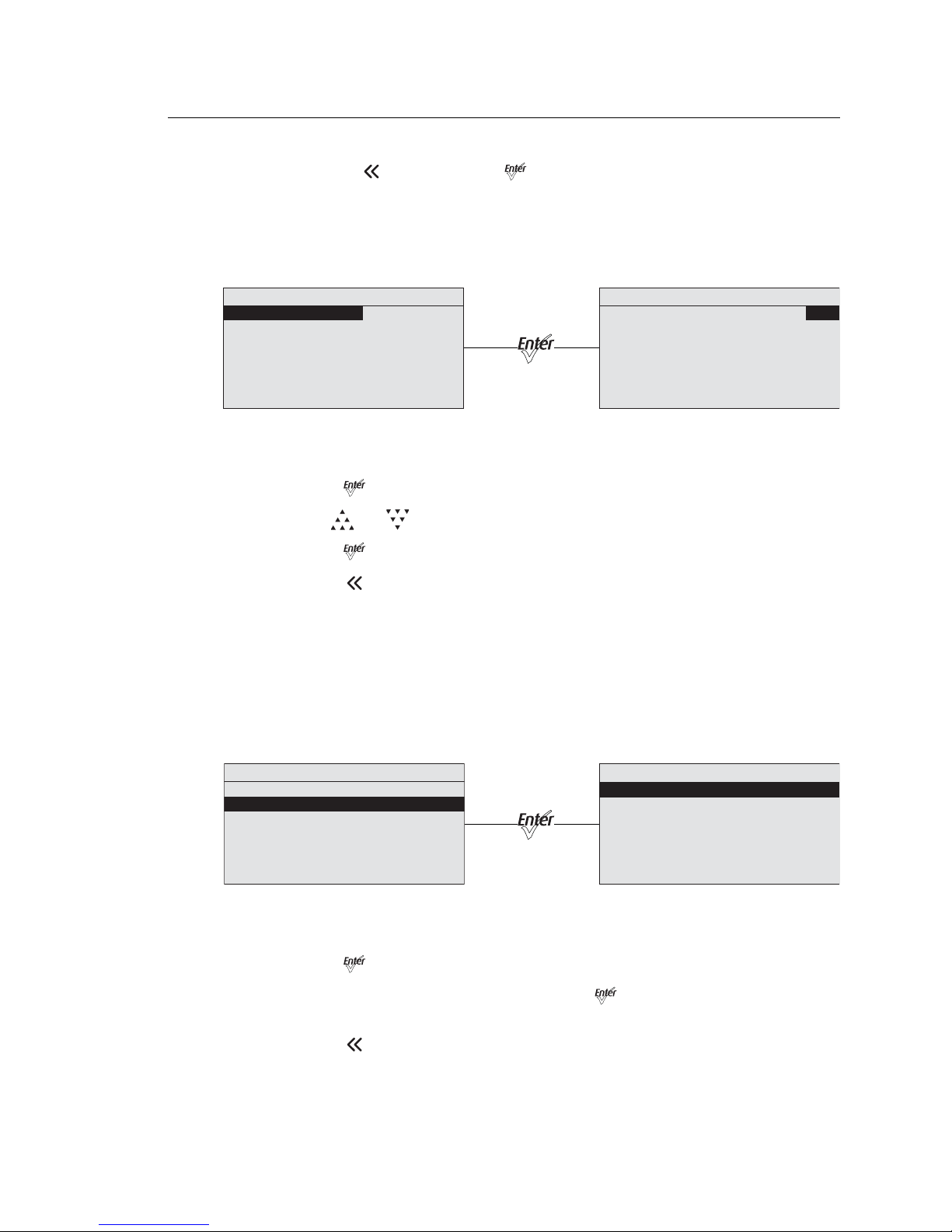
Figure-3.1 Selecting DMX Start Address on the Main Menu.
Step 1: On the Main Menu, scroll to DMX Start Address.
Step 2: Press [] to select the address number.
Step 3: Use [] or [] to scroll to the desired address.
Step 4: Press [].
Step 5: Press [] to return to the home screen.
Quick Setups
Quick Setups are groupings of predefined fixture performance settings, based on typical
applications.
Use the Quick Setups menu to select the desired setup. When a setup is active, the status
bar at the bottom of the screen indicates the DMX channels, their functions, and
arrangements that the setup uses.
Figure-3.2 Selecting Quick Setup on the Main Menu.
Step 1: On the Main Menu, scroll to Quick Setups.
Step 2: Press [].
Step 3: Scroll to the desired profile and then press [].
An asterisk (*) next to the profile name indicates that profile is active.
Step 4: Press [] to return to the home screen.
The top line of the home screen displays the name of the active profile.
Main Menu
DMX Start Address: 001
Quick Setups
Advanced Settings
Main Menu
DMX Start Address: 001
Quick Setups
Advanced Settings
Main Menu
DMX Start Address: 001
Quick Setups
Advanced Settings
Quick Setups
*General
Stage
High Impact
Studio
1/15 Hue Coarse
XT Arch
Page 53
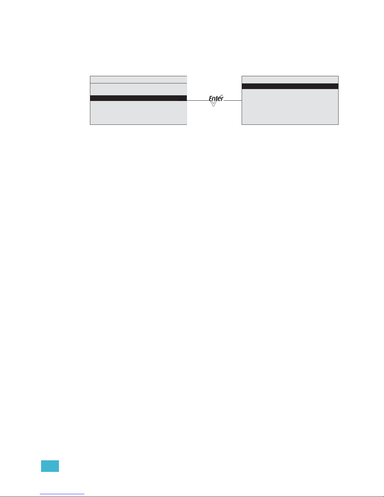
3 Operation 48
Advanced Settings
The Advanced Settings menu is for experienced users or for applications that entail very
carefully defined performance parameters. You can make individual adjustments of all
fixture settings for customized control.
Figure-3.3 Advanced Menu from the Main Menu.
When opening Advanced Settings, all fixture settings remain at their most recent values
until readjusted. The fixture automatically goes into Advanced Settings when any settings
are altered from one of the preset Quick Setups. Copy All Settings appears on the screen
only when DMX is not present.
Main Menu
DMX Start Address: 001
Quick Setups
Advanced Settings
Advanced Menu
DMX Settings
LED Settings
Presets and Sequences
Diagnostics
Local Settings
Copy All Settings
Page 54
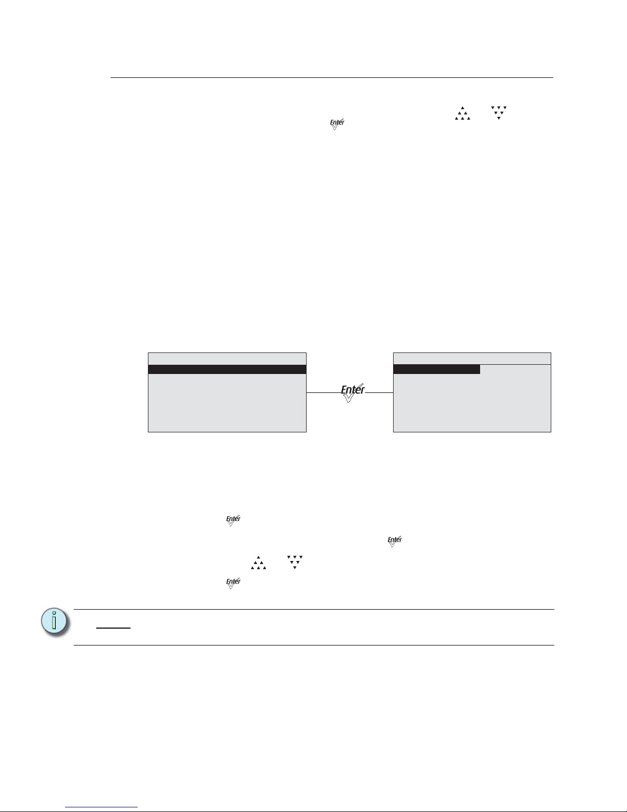
49 Source Four LED Profile v1.5.0 User Manual
Advanced Menu
The Advanced Menu provides access to various fixture settings and specific operations.
The Advanced Menu is accessed from the Main Menu by pressing [] or [] to select
Advanced Settings and then pressing [].
Copy All Settings appears on the screen only when DMX is not present. See Copy All
Settings, page 76.
DMX Settings
The current DMX settings are shown in the DMX Settings screen. Use the DMX Settings
screen to customize the following:
• DMX start address
• DMX profile
•Strobe
• Data loss
• Plus Seven (Lustr+ and Studio HD)
The two lower lines of the DMX Settings screen display the number of DMX channels used
by the fixture, according to the options selected, and their arrangement, in order.
Figure-3.4 Selecting DMX Settings from the Advanced Menu.
DMX Start Address
The DMX start address is selectable from 1 to 512.
Step 1: On the Advanced Menu, scroll to DMX Settings.
Step 2: Press [].
Step 3: With DMX Start Address selected, press [] to select the value.
Step 4: Then press [] or [] to set the desired address.
Step 5: Press [].
Step 6:
Note:
A change to the DMX start address on this screen will override and update the DMX
start address selected on the Home screen.
Advanced Menu
DMX Settings
LED Settings
Presets and Sequences
Diagnostics
Local Settings
Copy All Settings
DMX Settings
DMX Start Address: 101
DMX Profile: HSIC
Strobe: Enabled
Data Loss: Instant
Plus Seve n: En abled
DMX Profile: 6 chan
1/15 Hue Coarse
Page 55
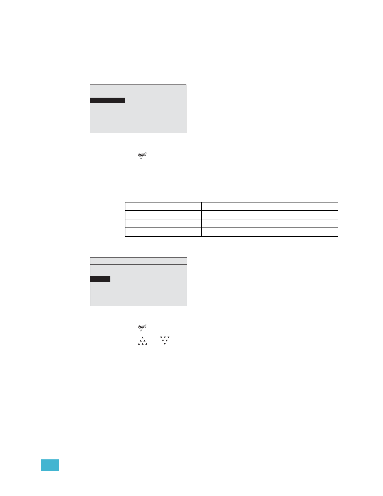
3 Operation 50
DMX Profile
The current DMX profile is displayed on the DMX Settings menu. You can customize the
setting by selecting a different profile. For detailed information about each profile, see
Profiles, page 30.
Step 1: On the DMX Settings menu, scroll to DMX Profile.
Figure-3.5 Selecting DMX Profile on the DMX Settings Menu.
Step 2: Press [] to set the desired profile.
Strobe
Strobe adds another DMX channel of control at channel 5 (or channel 9 when operating in
Direct Control profile). When enabled, the Strobe channel controls the fixture output as
follows.
Step 1: On the DMX Settings menu, scroll to Strobe.
Figure-3.6 Enabling Strobe on the DMX Settings Menu.
Step 2: Press [] to toggle between On and Off.
Step 3: Press [] or [] to commit the option.
DMX Value Strobe Effect
0 Full on
1 to 254 Variable rate from slow to fast
255 Full on
DMX Settings
DMX Start Address: 101
DMX Profile: HSIC
Strobe: Enabled
Data Loss: Instant
Plus Seve n: En abled
DMX Profile: 6 chan
3/15 S a t u r ation
DMX Settings
DMX Start Address: 101
DMX Profile: HSIC
Strobe: Enabled
Data Loss: Instant
Plus Seve n: En abled
DMX Profile: 6 chan
5/15 S t r o b e
Page 56
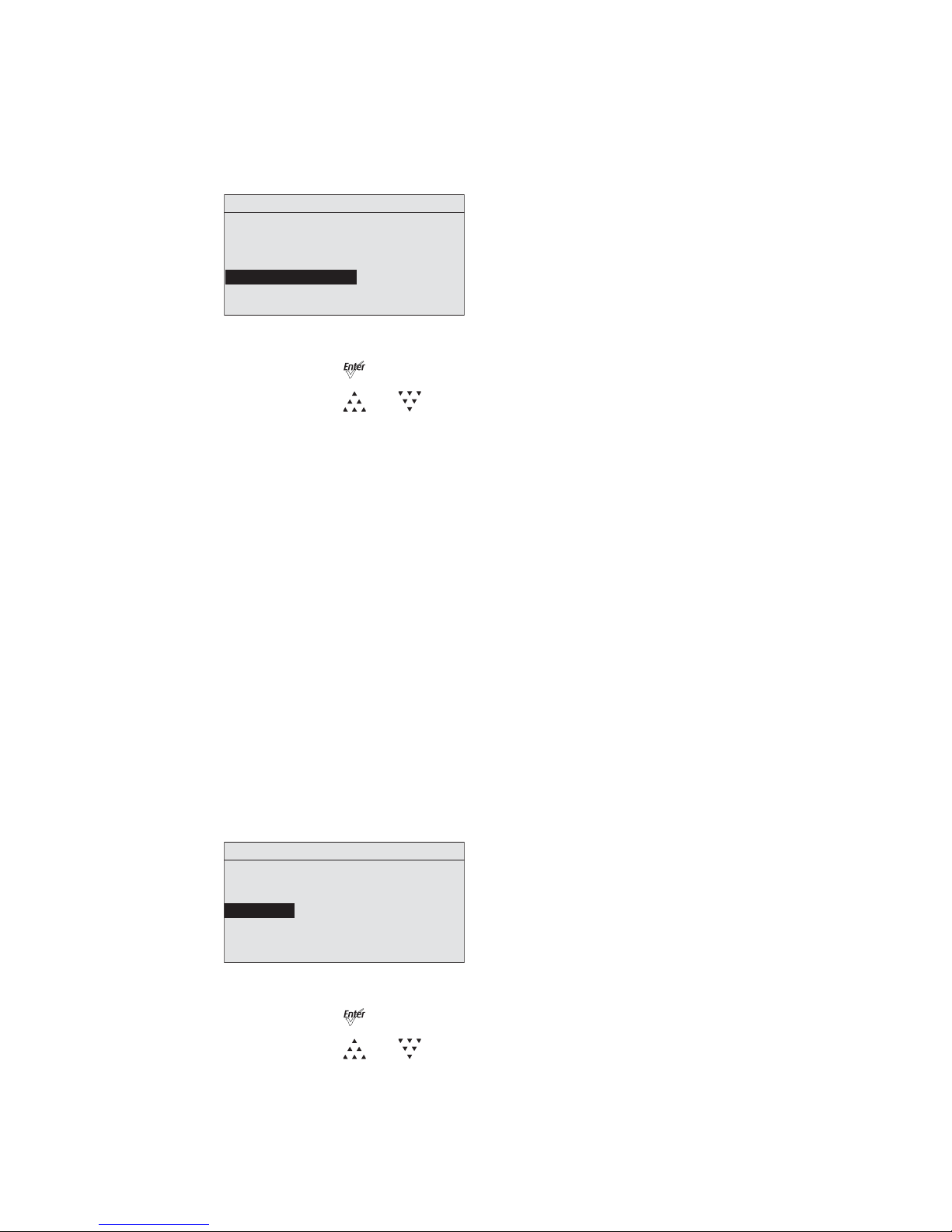
51 Source Four LED Profile v1.5.0 User Manual
Fan Control
Fan Control adds another DMX channel of control when set to DMX. Alternate settings are
Slow, Fast, and Automatic. For more information, see Fan Control, page 34.
Step 1: On the DMX Settings menu, scroll to Fan.
Figure-3.7 Setting the Fan Mode on the DMX Settings Menu.
Step 2: Press [] to scroll through the available options.
Step 3: Press [] or [] to commit the option.
Data Loss
Data Loss is what happens to the fixture's output when the external control signal (either
DMX or data from the Master fixture in a Master/Slave configuration) is lost. The choices
are as follows:
Instant
As soon as the control signal is lost, the fixture shuts off output and the LED array goes
black.
HLL-2Min
Hold last look for 2 minutes. The fixture retains its last setting for 2 minutes after the control
signal is lost, after which it shuts off output.
Cycling power to the fixture before the 2 minutes have passed will clear the last look and
the LEDs will remain off until control signal is restored.
HLL-4ever
Hold last look forever. After data is lost, the fixture maintains its last look until power is
removed from the fixture or control signal is restored. The last look will not be restored after
power has been cycled.
Step 1: On the DMX Settings menu, scroll to Data Loss.
Figure-3.8 Setting the Data Loss Type on the DMX Settings Menu.
Step 2: Press [] to toggle through the three options.
Step 3: Press [] or [] to commit the option.
DMX Settings
DMX Start Address: 101
DMX Profile: Direct
Strobe Mode: Enabled
Data Loss: Instant
Fan Mode: Auto
6/15 Fan
DMX Settings
DMX Start Address: 101
DMX Profile: HSIC
Strobe: Enabled
Data Loss: Instant
Plus Seve n: En abled
DMX Profile: 6 chan
2/15 Hue Fine
Page 57
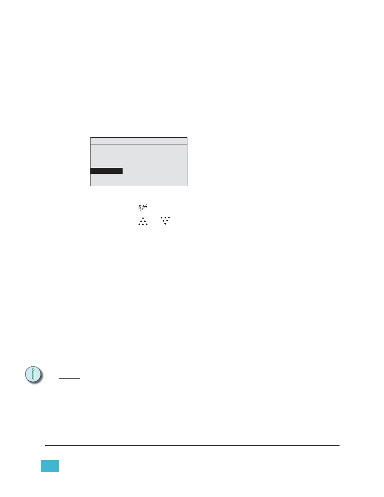
3 Operation 52
Plus Seven (Lustr+ and Studio HD)
Plus Seven allows enhanced color-mixing precision when using the RGB, HSI, HSIC, or
Studio profile as a starting point for color selection. Enabling Plus Seven adds another 8
DMX channels of control at the end of the control channels already in use by the fixture. For
example, in the HSIC profile, with Strobe enabled, the fixture uses 6 channels of control.
Enabling Plus Seven adds another 8 channels to the fixture, for a total of 14 channels of
control.
The first additional channel is an activation channel for the Plus Seven function. A value of
0 to 50% (DMX 0 to 129) deactivates Plus Seven. A value of 51 to 100% (DMX 130 to 255)
activates Plus Seven. The remaining 7 additional channels correspond to the individual
colors within the fixture's LED array.
Step 1: On the DMX Settings menu, scroll to Plus Seven.
Figure-3.9 Enabling Plus 7 on the DMX Settings Menu.
Step 2: Press [] to toggle between On and Off.
Step 3: Press [] or [] to commit the option.
Using Plus Seven Control
The following procedure is performed on your lighting console.
Step 1: Select a starting color point for the fixture output using the standard control
channels for RGB, HSI, etc.
Step 2: Set the first additional channel to a value between 51 and 100% to activate Plus
Seven.
Step 3: Refine the fixture output by altering one or more of the 7 individual color
channels.
• The starting point for each color is defined by the original color selection in
step 1.
• The brightness of each color can be increased or decreased from the starting
point to any value between zero and full output.
• Colors already at full output will not change when the Plus 7 channels are
moved up from the starting point, and colors already at zero output will not
change when the Plus 7 channels are moved down from the starting point.
Note:
Once any one of the seven individual color channels is altered from its neutral
starting position, the settings for the original color point may no longer reflect the
actual output of the fixture.
When using RGB, HSI, HSIC, or Studio profile for color selection, each fixture makes
accommodations for the specific LEDs in its array and produces output that is
consistent with other fixtures, whether or not they use LEDs from the same
production batch.
Operating with Plus Seven enabled can override this calibration, and multiple fixtures
may produce slightly different outputs when individual color channels are altered
from their neutral starting points.
DMX Settings
DMX Start Address: 101
DMX Profile: HSIC
Strobe: Enabled
Data Loss: Instant
Plus Seve n: Enabled
DMX Profile: 6 chan
1/15 Hue Coarse
Page 58
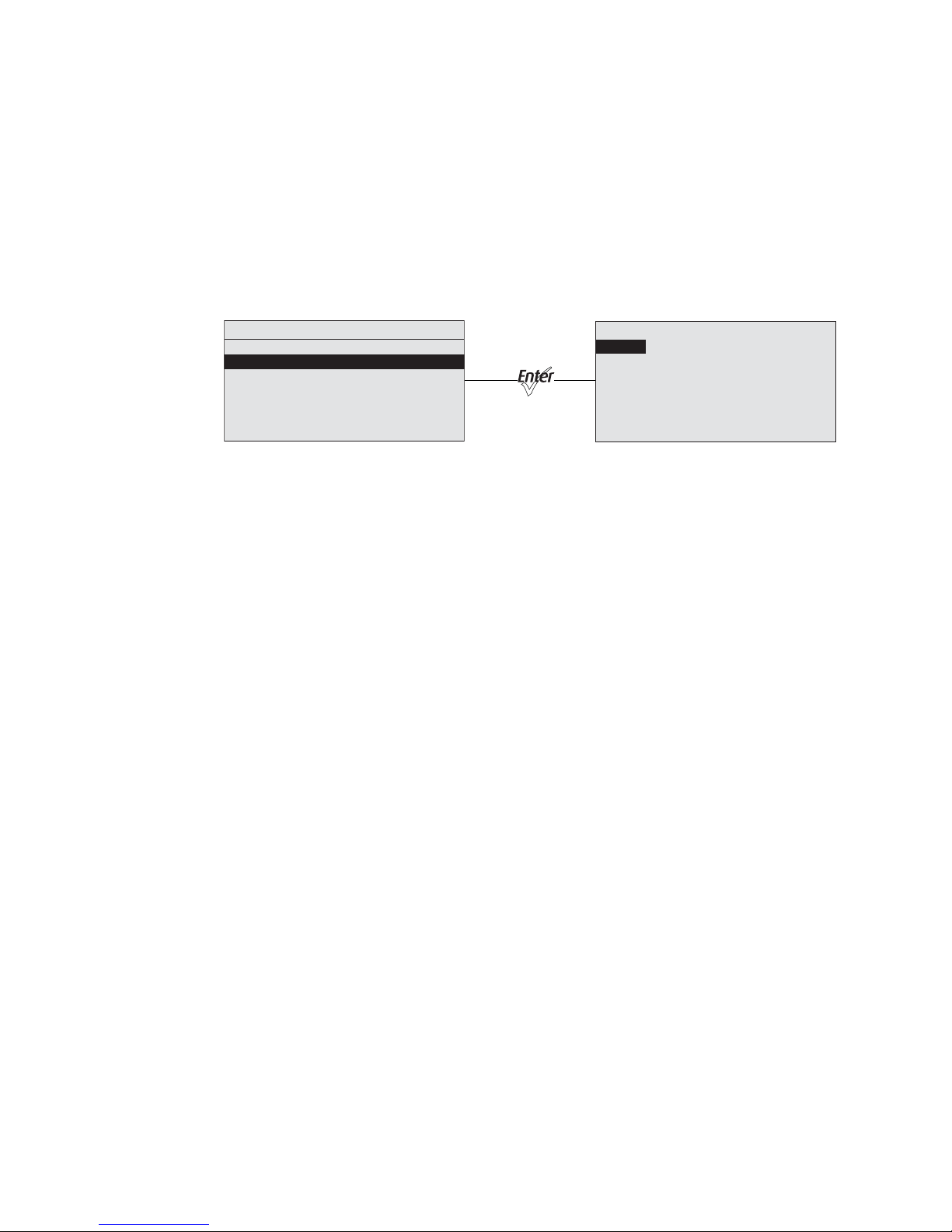
53 Source Four LED Profile v1.5.0 User Manual
LED Settings
Use the LED Settings menu to adjust fixture performance. From the LED Settings menu,
you can set the following.
• Output
•Curve
• Output Frequency
•Red Shift
• White Point
Figure-3.10 Selecting LED Settings on the Advanced Menu.
Output
Use Output to choose the optimal balance between two competing performance
parameters, maximum brightness and output consistency, by adjusting:
• How much the fixture limits the overall power to the LED array.
• How the fixture reduces output as internal fixture components heat up during use or in
high ambient temperatures.
The output options are as follows.
Regulated
Regulated is a moderately constrained power or brightness with consistent output under
typical use. Power to the LEDs is separately regulated in order to maintain consistent
brightness during the initial fixture warm-up period. This is recommended for most indoor
applications.
Protected
Protected provides the most consistent output possible with the greatest potential for
reduced overall brightness. This is best for outdoor use, changing environmental
temperatures, and applications with high requirements for consistency in extreme operating
conditions.
Boost
Boost provides the brightest possible output, with least guarantee of consistency. This is
best for applications with low duty cycles, loose brightness requirements, or where ambient
temperature is low.
LED Settings
Output: Regulated
Curve: Standard
Output Freq: 1200
Red Shift: Off
White Point: 3200K
Advanced Menu
DMX Settings
LED Settings
Presets and Sequences
Diagnostics
Local Settings
Copy All Settings
Page 59
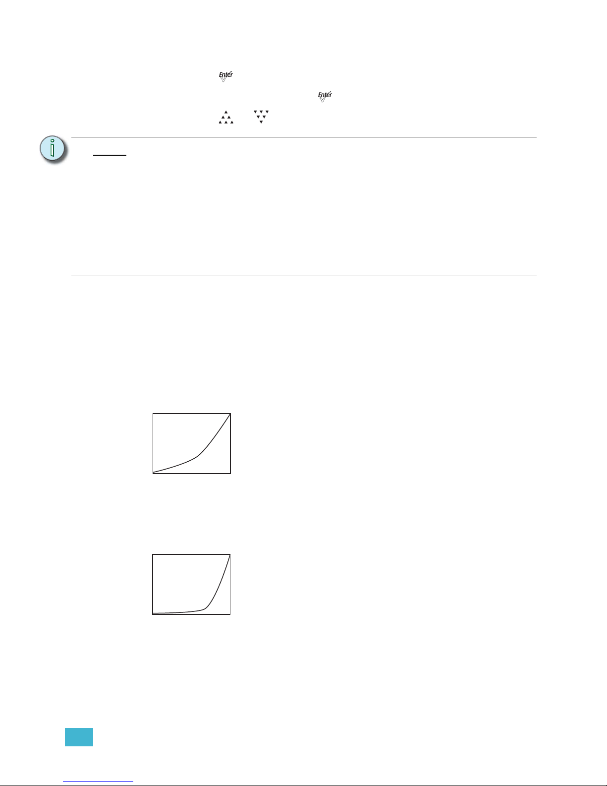
3 Operation 54
Step 1: On the Advanced Menu, scroll to LED Settings.
Step 2: Press [].
Step 3: With Output selected, press [] to toggle between the options.
Step 4: Press [] or [] to commit the option.
Curve
The dimming curve, commonly called curve, is the correlation between the change in the
value of the dimming control signal and the actual change in the fixture's brightness. Curve
is also the extent to which the fixture lags in its response time to the control signal in order
to facilitate smoothness in dimming.
Standard
Standard is a modest curve for intuitive brightness changes at both high and low ends of
the dimming range. Moderate lag in response for good smoothness. It allows quick jumps
in brightness. Suitable for most applications.
Incandescent
Exaggerated curve mimics the response of tungsten on a conventional dimmer. Lag is quite
pronounced and present even in full on or off bumps. Extreme smoothness with no instant
changes. Best when fixtures must operate in sync with incandescent sources.
Note:
All Output settings, if the fixture gets too warm and internal components approach
unsafe operating temperatures, the total power to the LED array is gradually reduced
and proportionate brightness levels between the various colors of LEDs are
maintained as much as possible in order to preserve the overall color mix; however,
some minor shifts in output may occur. Power continues to ramp down as much as
necessary until internal fixture components return to a safe temperature. The fixture
displays a warning message on the home screen indicating that power budgeting is
in place, showing the percent of total power that is currently used.
If the fixture exceeds its maximum internal temperature, the fixture enters a cooldown state, stops responding to the control signal, and it shuts down most or all
power to the LED array and displays its over-temperature status according to its
setting for over-temperature warning.
DMX
0 255
Intensity
DMX
0 255
Intensity
Page 60
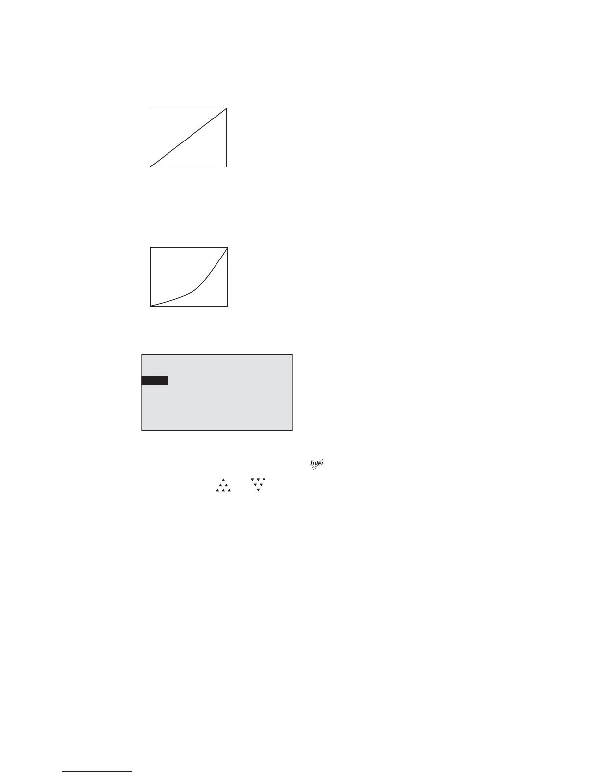
55 Source Four LED Profile v1.5.0 User Manual
Linear
Linear has no curve. Brightness levels correlate exactly with the value of the dimming
control signal. Moderate lag in response for good dimming smoothness. Linear allows quick
jumps in brightness. It is best for studio lighting and applications with static scenes or looks.
Quick
Quick uses the standard dimming curve but with no lag or smoothing. All changes are
instant and correlated exactly with the control input signal. Quick is best for extreme high
impact and video-based control.
Step 1: On the LED Settings menu, scroll to Curve.
Figure-3.11 Selecting Curve on the LED Settings Menu.
Step 2: With Curve selected, press [] to toggle between the options.
Step 3: Press [] or [] to commit the option.
DMX
0 255
Intensity
DMX
0 255
Intensity
LED Settings
Output: Regulated
Curve: Standard
Output Freq: 1200
Red Shift: Off
White Point: 3200K
Page 61
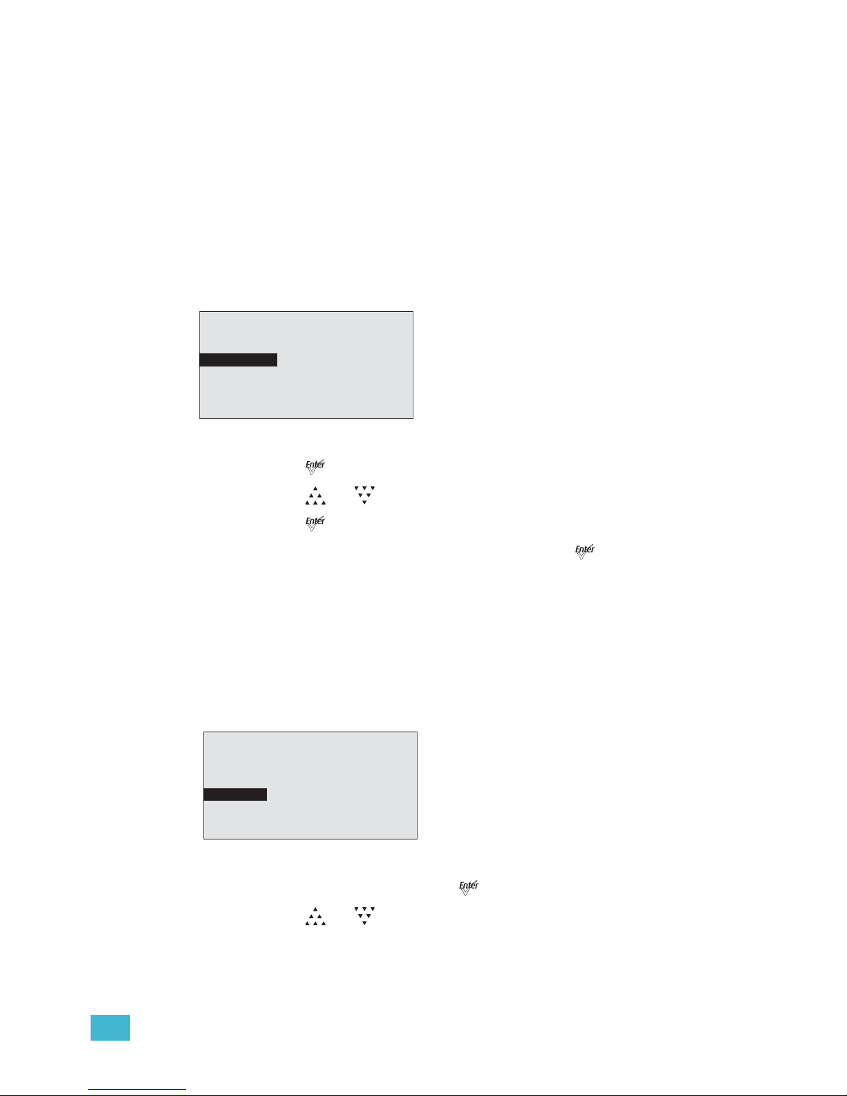
3 Operation 56
Output Freq
Output Frequency is the frequency in Hz at which the LED array pulses, or blinks, as a
function of Pulse-Width Modulation (PWM). The frequency is adjustable in order to avoid
visible flicker on video and film. When altering the frequency in order to reduce noticeable
flicker on camera, often only a small change is required. The range is 920 to 1500 Hz in
increments of 10. The default value is 1200 Hz.
For high speed exposure or rolling shutter cameras, use the High 25K mode. This increases
the PWM to 25,000 Hz and will result in flicker-free operation in most circumstances. To
access the High 25K, press the up arrow after reaching 1500 Hz in the Output Freq: field.
Changing the frequency from the default value can have a slight impact on the smoothness,
or color-mix consistency, or both when dimming.
Step 1: On the LED Settings menu, scroll to Output Freq.
Figure-3.12 Selecting Output Frequency on the LED Settings Menu.
Step 2: Press [] to select the value.
Step 3: Press [] or [] to set the desired value.
Step 4: Press [].
Step 5: When asked if you are sure, select Yes and press [].
Red Shift
Red shift allows the fixture to match its dimming performance to that of a conventional
tungsten lamp. The fixture automatically changes its apparent White Point, or color
temperature, as a function of overall intensity. Red shift works with both white-light and
colored-light output settings. It is also known as amber drift and tungsten shift. Red shift is
available only in the HSI and RGB profiles. It is not available on Daylight and Tungsten
fixtures.
Step 1: On the LED Settings menu, scroll to Red Shift.
Figure-3.13 Selecting Red Shift on the LED Settings Menu.
Step 2: With Red Shift selected, press [] to toggle between On and Off.
Step 3: Press [] or [] to commit the option.
LED Settings
Output: Regulated
Curve: Standard
Output Freq: 1200
Red Shift: Off
White Point: 3200K
LED Settings
Output: Regulated
Curve: Standard
Output Freq: 1200
Red Shift: Off
White Point: 3200K
Page 62
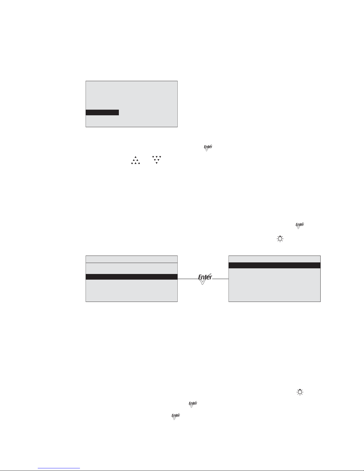
57 Source Four LED Profile v1.5.0 User Manual
White Point (Lustr+ and Studio HD)
White Point controls the appearance (color temperature) of white-light output when
saturation is at or near zero. This option is available when using the HSI and RGB profiles.
The choices are 2950K, 3200K, 5600K, and 6500K.
Step 1: On the LED Settings menu, scroll to White Point.
Figure-3.14 Selecting White Point on the LED Settings Menu.
Step 2: With White Point selected, press [] to toggle between the options.
Step 3: Press [] or [] to commit the option.
Presets & Sequences
When no external control signal is connected to the fixture, it can be set to run a preset color
mix or a sequence of presets in a stand-alone operation. The Presets and Sequences
screen provides access to the edit screens for Presets and for Sequences, and it indicates
which Preset or Sequence is active, if any. You can access the Presets and Sequences
menu by doing either of the following.
•On the Advanced Menu, scroll to Presets and Sequences and press [].
• From any menu, except when operating in Studio profile, press [].
Figure-3.15 Selecting Presets and Sequences on the Advanced Menu.
Focus
Focus is independent of any of the other settings or presets and works whether or not the
fixture is receiving DMX data from a console or is in a Preset or stand-alone state. Focus
stays on until you disable it or power is disconnected. It turns every LED in the fixture on at
70% so you can:
• Focus (aim) the fixture prior to console set-up or when there is no one at the console
to give the fixture intensity.
• Double-check that the fixture is working and that all LEDs are operational.
Step 1: From the Advanced Menu select Presets and Sequences or press [].
Step 2: With Focus selected, press [] to turn the fixture On.
Step 3: When finished, press [] to turn the fixture Off.
LED Settings
Output: Regulated
Curve: Standard
Output Freq: 1200
Red Shift: Off
White Point: 3200K
Advanced Menu
DMX Settings
LED Settings
Presets and Sequences
Diagnostics
Local Settings
Copy All Settings
Presets and Sequences
Focus: Off
Presets
Quick Color
Sequences
Preset 1 is Active
No Sequence is Active
Page 63
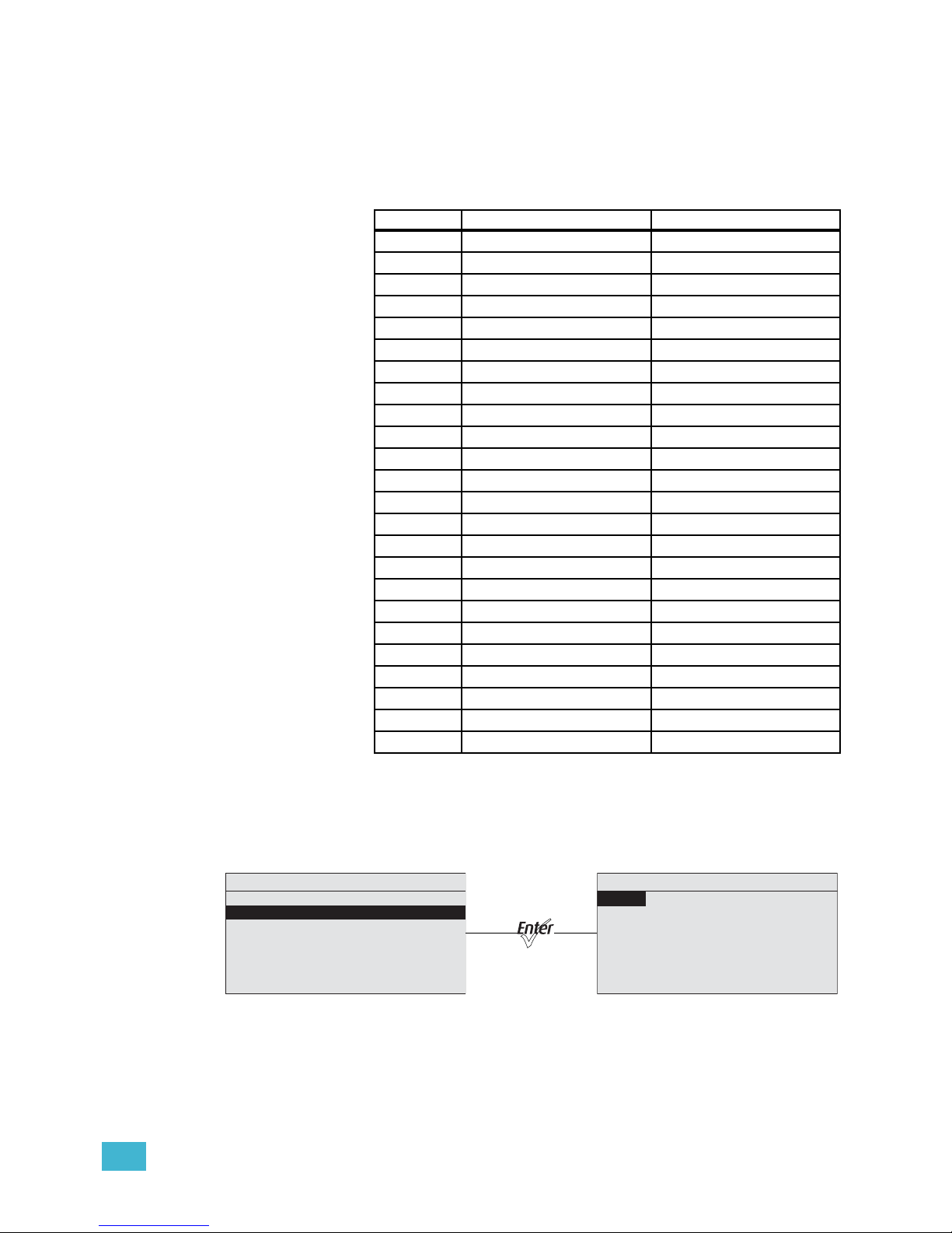
3 Operation 58
Presets (Lustr+ and Studio HD)
A Preset is a single, static look or color mix. The Source Four LED series fixture comes with
24 default configurations. Only one Preset can be active at a time. You can activate any of
the Preset color mixes and customize each one.The following table lists the default Preset
color mixes, most of which are also available as Quick Color options. See “Quick Color
(Lustr+, Studio HD)” on page 67.
Presets (Daylight and Tungsten)
The Daylight and Tungsten fixtures come with 24 available slots for Presets. Only one
Preset can be active at a time. You can activate any of the Presets and customize each
one. Daylight and Tungsten fixtures have Presets that can define both Intensity and Strobe
values. There are no default Presets that come pre-configured from the factory.
Figure-3.16 Selecting Presets on the Presets and Sequences Menu.
Preset Default Color Available as Quick Color
1White Yes
2Warm Yes
3 Cool Yes
4 Minus Green Yes
5 Lite Pink Yes
6 Lite Gold Yes
7 Yellow Yes
8 Dark Straw Yes
9 Dark Amber Yes
10 Orange Yes
11 Re d -12 Med Pink Yes
13 Dark Pink Yes
14 Magenta -15 Purple Yes
16 Dark Lavender Yes
17 Deep Purple Yes
18 Clear Blue Yes
19 Lite Blue Yes
20 Med Blue Yes
21 Primary Blue Yes
22 Blue-Green Yes
23 Lite Green Yes
24 Green --
Presets
Preset: * 23
Status: Active
Fade Time: 00:02
Delay Time: 00:00
Edit
Copy to Other Fixture
Save DMX as Preset
Presets and Sequences
Focus: Off
Presets
Sequences
Quick Color
Preset 1 is Active
No Sequence is Active
Page 64
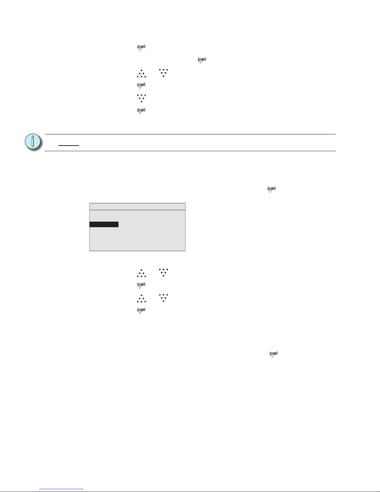
59 Source Four LED Profile v1.5.0 User Manual
Step 1: On the Presets and Sequences menu, scroll to Presets.
Step 2: Press [].
Step 3: With Preset selected, press [].
Step 4: Press [] or [] to set the desired preset number.
Step 5: Press [].
Step 6: Press [] to select Status.
Step 7: Press [] to activate the Preset.
The action changes to Active and an asterisk (*) displays in front of the preset
number.
Fade Time
Fade time is the length of time the fixture takes to crossfade from the previous setting to the
Preset. The format is MM:SS. The default is 2 seconds.
Step 1: On the Presets menu, scroll to Fade Time and press [].
Figure-3.17 Selecting Fade Time on the Presets Menu.
Step 2: Press [] or [] to set the desired time in minutes.
Step 3: Press [].
Step 4: Press [] or [] to set the desired time in seconds.
Step 5: Press [].
Delay Time
Delay time is the length of time the fixture waits on the previous setting before initiating the
crossfade to the Preset. The default is 0 seconds.
Step 1: On the Presets menu, scroll to Delay Time and press [].
Note:
You cannot activate a Preset if the fixture is receiving an external DMX control signal.
Presets
Preset: * 23
Status: Active
Fade Time: 00:02
Delay Time: 00:00
Edit Color
Copy to Other Fixture
Save DMX as Preset
Page 65
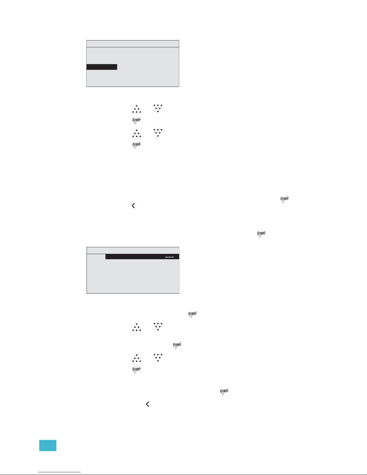
3 Operation 60
Figure-3.18 Selecting Delay Time on the Presets Menu.
Step 2: Press [] or [] to set the desired time in minutes.
Step 3: Press [].
Step 4: Press [] or [] to set the desired time in seconds.
Step 5: Press [].
Edit Color (Lustr+ and Studio HD)
Use Edit Color to change the overall brightness settings of all colors within the LED array.
You can change the predefined color mixes for the Preset. Refer to the table in Presets
(Lustr+ and Studio HD), page 58. You can also change the hue, saturation and intensity of
the predefined colors.
To keep your changes, be sure to select Save Changes and then press
[]. To discard
changes press [] at any time.
If the Preset is currently active, the changes made on the Preset Color Edit screen update
to the fixture output immediately.
Step 1: On the Presets menu, scroll to Edit Color and press [].
Figure-3.19 Edit Preset Color Screen.
Step 2: With Color selected, press [].
Step 3: Press [] or [] to set the desired predefined color mix.
Step 4: Alternatively, to edit the predefined color mix, scroll to any of the parameters on
the screen and press [].
Step 5: Press [] or [] to change the values.
Step 6: Press [].
Step 7: Do one of the following:
• Scroll to Save Changes and press [].
• Press [] to exit the screen without saving the changes.
Presets
Preset: * 23
Status: Active
Fa d e Ti m e: 00:02
Delay Time: 0 0:0 0
Edit Color
Copy to Other Fixture
Save DMX as Preset
Preset 23 Color Edit
Color:
Int: 100%
Save Changes
Strobe: 255
Page 66
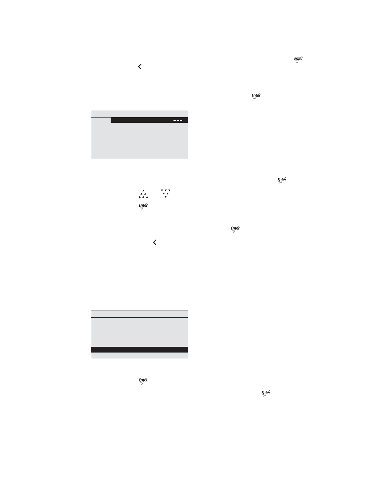
61 Source Four LED Profile v1.5.0 User Manual
Edit (Daylight and Tungsten)
Use Edit to change the brightness and strobe settings of the LED array.
To keep your changes, be sure to select Save Changes and then press
[]. To discard
changes press [] at any time.
If the Preset is currently active, the changes made on the Preset Edit screen update to the
fixture output immediately.
Step 1: On the Presets menu, scroll to Edit and press [].
Figure-3.20 Edit Preset Screen.
Step 2: Scroll to any of the parameters on the screen and press [].
Step 3: Press [] or [] to change the values.
Step 4: Press [].
Step 5: Do one of the following
• Scroll to Save Changes and press [].
• Press [] to exit the screen without saving the changes.
Copy to Other Fixtures
If other fixtures are connected to the same data chain, you can copy the Preset values to
the other fixtures. The fixture automatically becomes the Master and controls all the other
fixtures (Slaves) in the chain until another fixture has its Preset or Sequence settings
selected or activated. For more information, see Master/Slave Operation, page 67.
Step 1: On the Presets screen, scroll to Copy to Other Fixtures.
Figure-3.21 Copy the Preset to Other Fixtures.
Step 2: Press [].
Step 3: When asked if you are sure, select Yes and press [].
Preset 23 Edit
Color:
Int: 255
Save Changes
Strobe: 0
Presets
Preset: * 23
Status: Active
Fa d e Ti m e: 00:02
Delay Time: 00:00
Edit Color
Copy to Other Fixture
Save DMX as Preset
Page 67
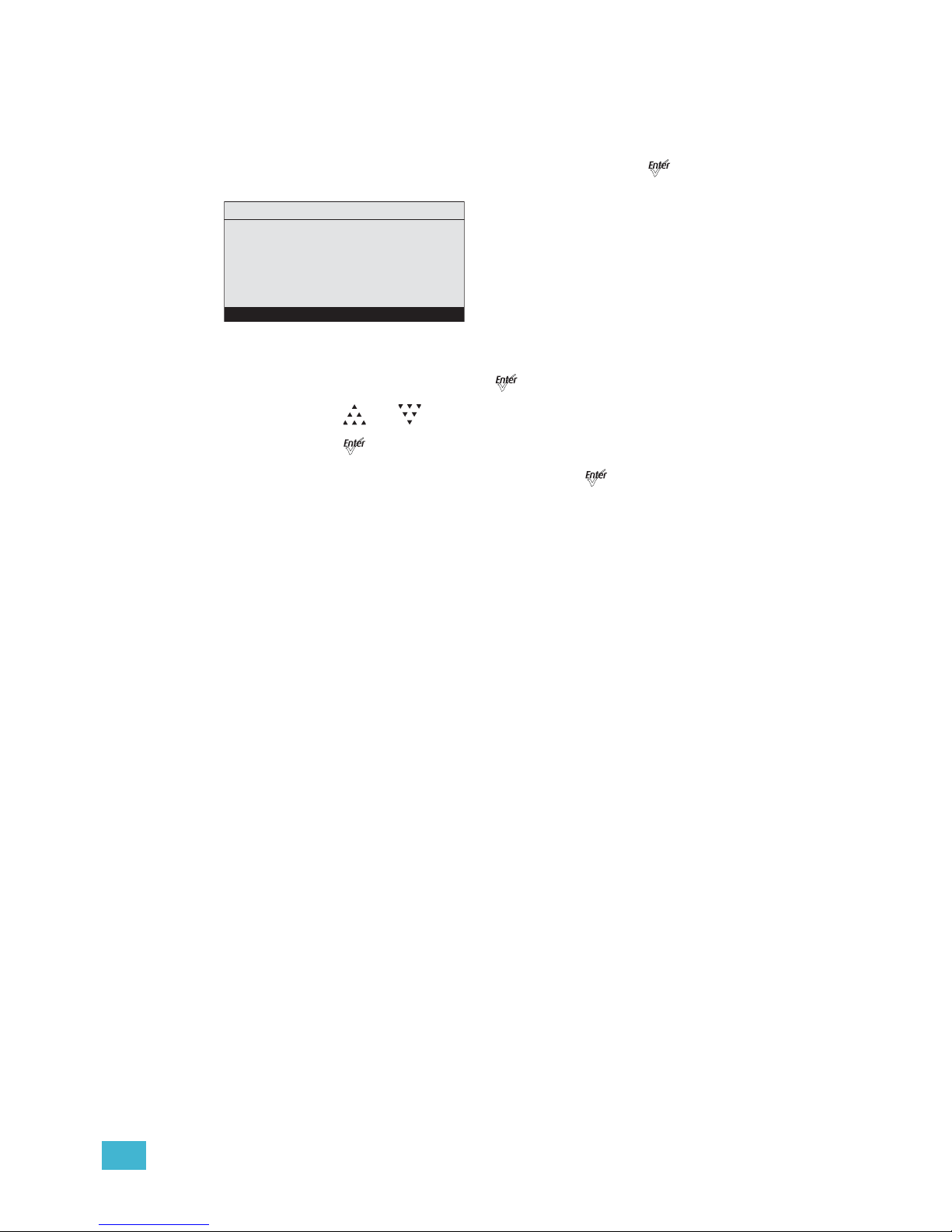
3 Operation 62
Save DMX as Preset
You can take a snapshot of the incoming DMX signal when the fixture is in HSI mode and
save it as a preset value.
Step 1: On the Presets screen, scroll to Preset and press [].
Figure-3.22 Save the DMX as a Preset.
Step 2: With Preset selected, press [].
Step 3: Press [] or [] to set the desired preset number.
Step 4: Press [].
Step 5: Scroll to Save DMX as Preset and press [].
Presets
Preset: * 23
Status: Active
Fa d e Ti m e: 00:02
Delay Time: 00:00
Edit Color
Copy to Other Fixture
Save DMX as Preset
Page 68
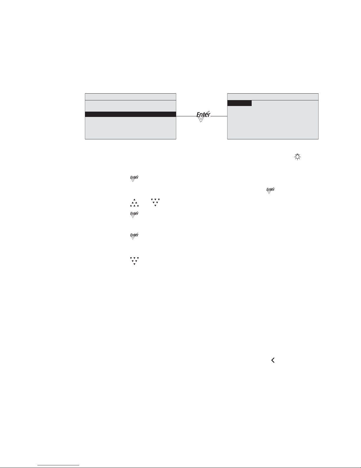
63 Source Four LED Profile v1.5.0 User Manual
Sequences
A Sequence is a timed series of presets. Up to 12 different Sequences may be altered for
Preset selections, crossfade rate, and link time. Only one Preset can be active at a time.
The sequences can be copied to other fixtures in the same data chain.
You can create your own custom sequence that includes two or more Presets. For
example, you may want to sequence through Presets 2, 4, 23, and 1, in that order. As you
enter these into the sequence, you also can set the rate and link time for each step.
Figure-3.23 Selecting Sequences on the Presets and Sequences Menu.
Step 1: From the Advanced Menu select Presets and Sequences or press [].
Step 2: On the Presets and Sequences menu, scroll to Sequences.
Step 3: Press [].
Step 4: On the Sequences menu, with Sequence selected, press [].
Step 5: Press [] or [] to set the desired Sequence number.
Step 6: Press [].
Step 7: Scroll to Status.
Step 8: Press [] to activate the Sequence.
The screen changes to Active and an asterisk (*) displays in front of the preset
number.
Step 9: Press [] to scroll to Rate.
Rate
Rate is the execution of the Presets' Fade Times and Delay Times within the Sequence,
relative to their settings within the actual Presets. The available Rate range is 2 to 500%.
The default is 100%.
A Rate of 100% represents running the Sequence with timing exactly as specified within
the Presets. A Rate above 100% represents running the Sequence with faster timing than
specified within the Presets. For example, with a Rate of 200%, a Preset with a Fade Time
of 6 seconds would actually be run within the Sequence in only 3 seconds.
A Rate below 100% represents running the Sequence with slower timing than specified
within the Presets. For example, with a Rate of 50%, a Preset with a Fade Time of 6
seconds would actually be run within the Sequence in 12 seconds.
Any change to the Rate is updated live in the fixture memory. Pressing [] does not undo
a change to Rate.
Sequences
Sequence: * 3
Action: Not Active
Rate: 100%
Step: 01
Preset: 1
Link Time: 00:02
Copy to Other Fixture
Presets and Sequences
Focus: Off
Presets
Sequences
Quick Color
Preset 1 is Active
No Sequence is Active
Page 69
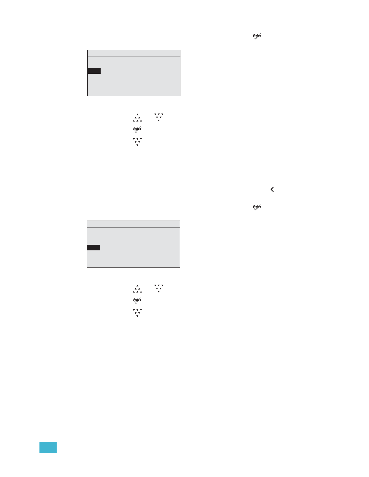
3 Operation 64
Step 1: On the Sequences menu, scroll to Rate and press [].
Figure-3.24 Selecting Rate on the Sequences Menu.
Step 2: Press [] or [] to set the desired percent.
Step 3: Press [].
Step 4: Press [] to scroll to Step.
Step
You enter the number of the step in the sequence to be edited. In our example, you select
step 1. After setting the Preset and Link time, return to Step and select step 2. Repeat this
process until you have entered all the steps in the sequence.
Any change to Step is updated live in the fixture memory. Pressing [] does not undo a
change to Step.
Step 1: On the Sequences menu, scroll to Step and press [].
Figure-3.25 Selecting Step on the Sequences Menu.
Step 2: Press [] or [] to set the desired Step number.
Step 3: Press [].
Step 4: Press [] to scroll to Preset.
Sequences
Sequence: * 3
Action: Not Active
Rate: 100%
Step: 01
Preset: 1
Link Time: 00:02
Copy to Other Fixture
Sequences
Sequence: *3
Action: Not Active
Rate: 100%
Step: 01
Preset: 1
Link Time: 00:02
Copy to Other Fixture
Page 70
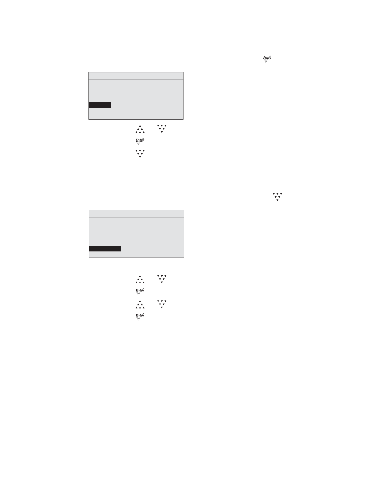
65 Source Four LED Profile v1.5.0 User Manual
Preset
Preset is the number of a Preset, whether it is a predefined or a custom color mix.
Step 1: On the Sequences menu, scroll to Preset and press [].
Step 2: Press [] or [] to set the desired Preset number.
Step 3: Press [].
Step 4: Press [] to scroll to Link Time.
Link Time
Link Time is the length of time the fixture waits before moving from one Preset to the next.
The format is MM:SS. The default is 2 seconds.
Step 1: On the Sequences menu, scroll to Link Time and press [].
Figure-3.26 Selecting Link Time on the Sequences Menu.
Step 2: Press [] or [] to set the desired time in minutes.
Step 3: Press [].
Step 4: Press [] or [] to set the desired time in seconds.
Step 5: Press [] to commit the values.
Finishing the Sequence
After each of the steps have been configured, set the End State. End state is what the
fixture does once it completes the Sequence. Two end state options are available and both
options repeat indefinitely until the Sequence is deactivated. To access the end state
options, you must first program an additional and final step within the sequence using
Preset 0. Preset 0 marks the end of the Sequence and opens the End State menu line.
Preset 0 may only be used once within a Sequence. If you want the Sequence to repeat
automatically, you may only define up to 23 steps with Presets 1 through 24, since the final
step must be reserved for Preset 0.
Loop
Once the fixture completes the entire sequence, it immediately returns to the beginning and
starts the sequence over again, in order.
Sequences
Sequence: *3
Action: Not Active
Rate: 100%
Step: 01
Preset: 1
Link Time: 00:02
Copy to Other Fixture
Sequences
Sequence: *3
Action: Not Active
Rate: 100%
Step: 01
Preset: 1
Link Time: 00:02
Copy to Other Fixture
Page 71
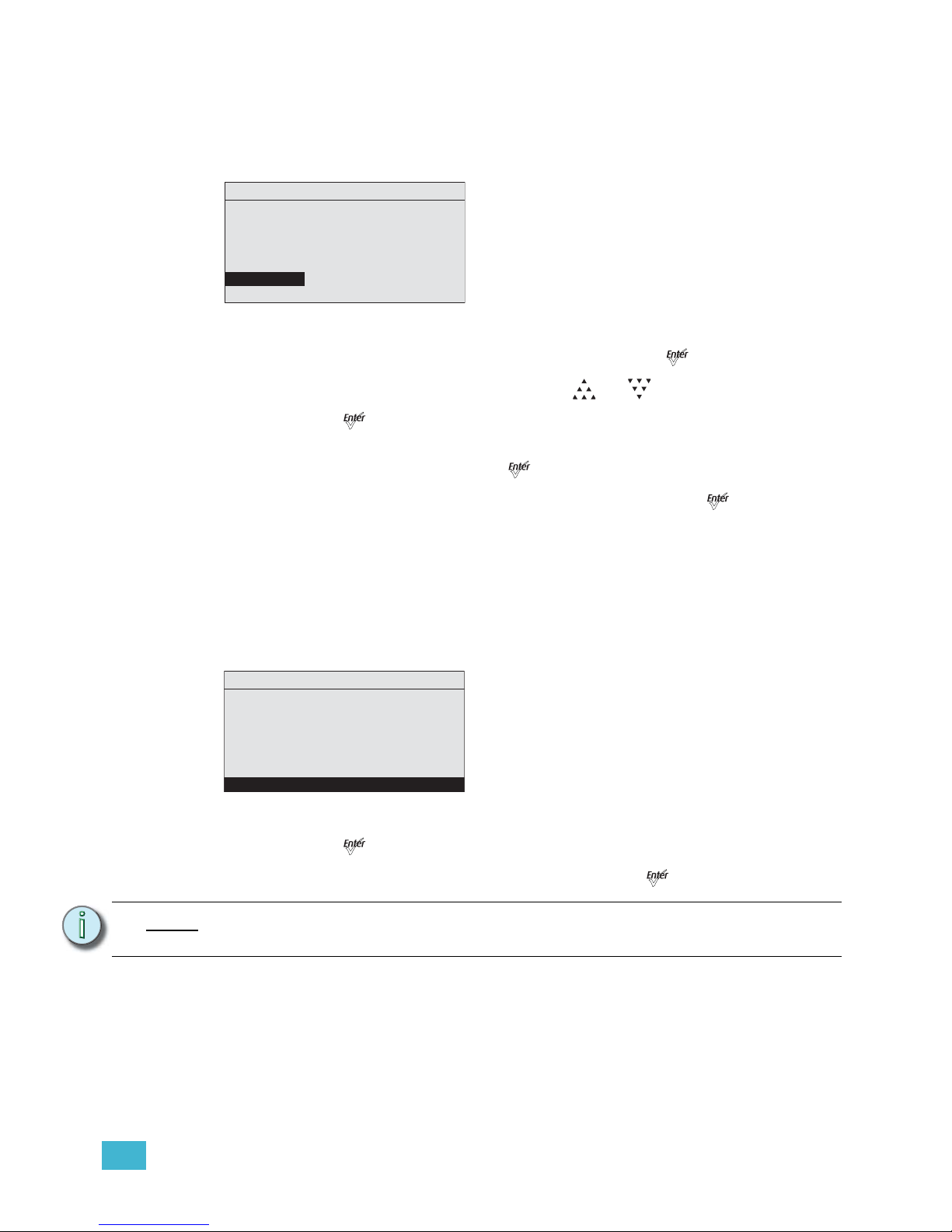
3 Operation 66
Bounce
Once the fixture completes the entire sequence, it reverses the order of the presets and
steps backward through them until reaching the starting step, at which point it starts the
Sequence over again, in the original order.
Figure-3.27 Setting Sequences End State.
Step 1: On the Sequences menu, scroll to Preset and press [].
Step 2: With the Preset number selected Press [] or [] until you reach 0.
Step 3: Press [].
Link Time on the screen is replaced with End State.
Step 4: Scroll to End State and press [] to toggle between the options.
Step 5: If the Sequence is not active, scroll up to Status and press [].
Copy to Other Fixtures
If other fixtures are connected to the same data chain, you can copy the Sequences
settings to the other fixtures. The fixture automatically becomes the Master and controls all
the other fixtures (Slaves) in the chain until another fixture has its Preset or Sequence
settings selected or activated. For more information, see Master/Slave Operation, page 67.
Step 1: On the Sequences screen, scroll to Copy to Other Fixtures.
Figure-3.28 Selecting Copy to Other Fixtures.
Step 2: Press [].
Step 3: When asked if you are sure, select Yes and press [].
Note:
This option only copies Sequence data; it does not copy changes to the Preset
settings or color mixes used within the Sequence.
Sequences
Sequence: * 3
Status: Active
Rate: 100%
Step: 01
Preset: 0
End State: Loop
Copy to Other Fixture
Sequences
Sequence: * 3
Status: Active
Rate: 100%
Step: 01
Preset: 0
End State: Loop
Copy to Other Fixture
Page 72
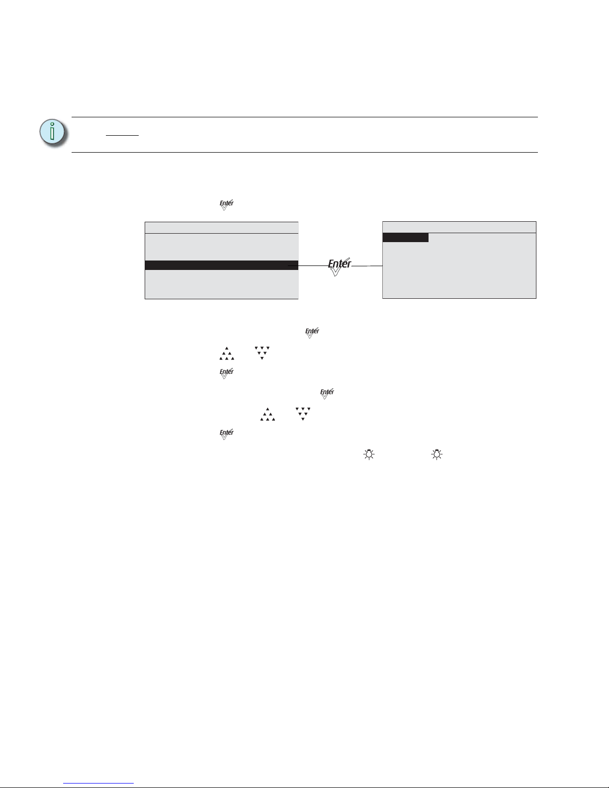
67 Source Four LED Profile v1.5.0 User Manual
Quick Color (Lustr+, Studio HD)
Quick Color allows you to easily select a color and its intensity from a predefined menu.
This feature overrides any presets or sequences previously selected and is only available
when there is no external DMX signal to the fixture. For a list of available colors, see the
table on page 58.
To select a Quick Color:
Step 1: Scroll to Quick Color within the Presets and Sequences screen.
Step 2: Press [].
Figure-3.29 Selecting Quick Color on the Presets and Sequences Menu.
Step 3: Scroll to Color and press [].
Step 4: Press [] or [] to select the desired color
Step 5: Press [] to commit the selection.
Step 6: Scroll to Intensity and press [].
Step 7: Press and hold [] or [] to adjust the fixture’s intensity.
Step 8: Press [] to commit the selection.
• To set the Intensity to 0, press the []. Pressing [] a second time will
return the fixture to its previously set Intensity.
• If power to the fixture is lost while in Quick Color mode, the fixture will return
to the Quick Color menu once power is restored.
Master/Slave Operation
When similar fixtures' DMX or data connections are linked together and there is no external
DMX signal going to them, one fixture automatically controls all other fixtures in the chain
when a Preset or Sequence is initiated.
Master
Master is the one fixture that controls all fixtures in the daisy chain. By default, it is
whichever fixture had its Preset or Sequence selected or adjusted most recently. The
Master fixture can only control Slave fixtures to produce identical output at the same time
as itself. The Master fixture cannot control Slave fixtures to operate individually or to run
chase-type or time-offset sequences.
Changes and edits to Presets or Sequences that are made to the Master fixture may be
copied to the internal memory of all Slave fixtures for later use when these fixtures are
disconnected from the data daisy chain.
Note:
Exiting the Quick Color menu will return the fixture to the state it was in before
entering the menu.
Presets and Sequences
Focus: Off
Presets
Sequences
Quick Color
Preset 1 is Active
No Sequence is Active
Quick Color
Intensity: 100%
Color:
–––
Page 73
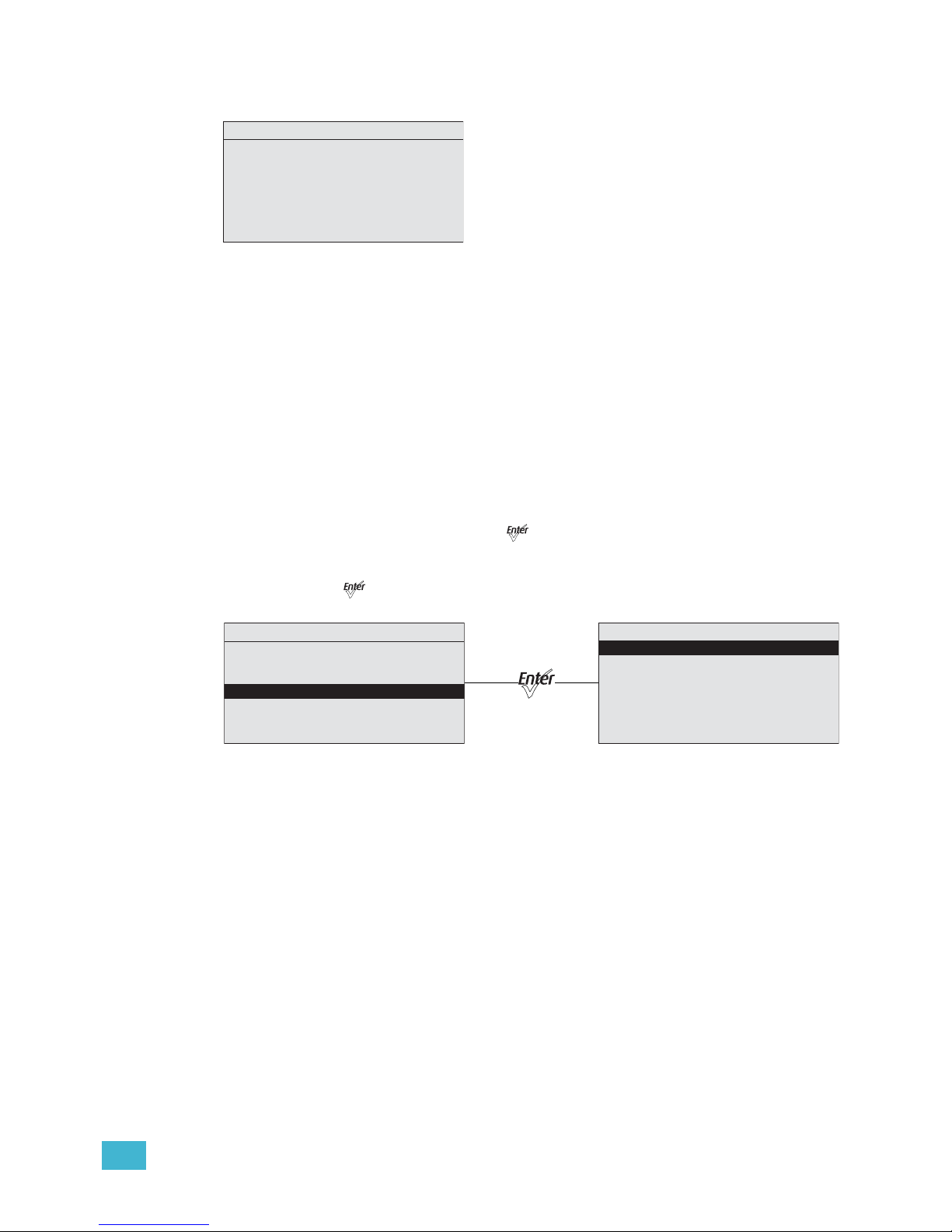
3 Operation 68
When operating as the Master fixture, the fixture displays Master on its home screen.
Figure-3.30 XYZ Status Screen Showing Master.
Slave
Any fixture in the data chain that is being controlled by the master fixture. By default, all
fixtures are slaves, except the one that had its Preset or Sequence altered most recently.
A Slave fixture can only directly imitate the performance of the Master fixture.
When operating as a Slave fixture, the fixture displays Slave on its home screen.
Diagnostics
The Diagnostics menu provides access to detailed information about various aspects of the
fixture’s performance. Diagnostics also provides access to test functions and fixture
recalibration. Much of the Diagnostics menu is used by service technicians to troubleshoot
problems.
Step 1: From the home screen, press [] to open the Main Menu.
Step 2: Scroll to Advanced Settings.
Step 3: Press [].
Figure-3.31 Selecting Diagnostics on the Advanced Menu.
Current DMX In
The Current DMX In screen displays the values of the current DMX input by channels. The
values dynamically change as the DMX input changes. This screen is a read-only screen,
which displays the following.
• The Control Input setting.
• The DMX channel assignment, in order.
• The current DMX value (0-255) of each control channel in use by the fixture.
• The current brightness (0 to full or 00 to FL) of each series of LEDs in the fixture's LED
array.
Studio
Master
Preset 1 is Active
System OK
No Sequence is Active
Studio Prt Lin – – Str
1/5 In te n s i t y
Advanced Menu
DMX Settings
LED Settings
Presets and Sequences
Diagnostics
Local Settings
Copy All Settings
Diagnostics
Current DMX In
Network Statistics
Tes t
Recalibrate Fixture
About Fixture
Page 74
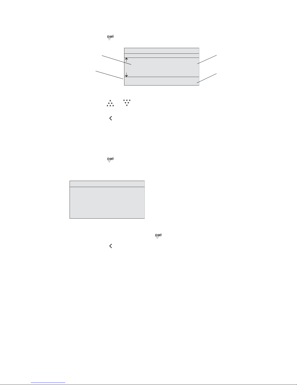
69 Source Four LED Profile v1.5.0 User Manual
Step 1: On the Diagnostics screen, scroll to Current DMX In.
Step 2: Press [].
Figure-3.32 Current DMX In Screen with Dynamic Values.
Step 3: Press [] or [] to scroll through the channels. Arrows on the left indicate that
you can scroll up or down.
Step 4: Press [] to return to the Diagnostics screen.
Network Statistics
The Network Statistics screen displays the statistics of the network. The DMX input values
dynamically change. This screen is read-only.
Step 1: On the Diagnostics screen, scroll to Network Statistics.
Step 2: Press [].
When you access the screen, the dynamic values start at 0 and continue to
increase.
Figure-3.33 Network Statistics Screen with Dynamic values.
Step 3: To reset the counters, press [].
Step 4: Press [] to return to the Diagnostics screen.
Current DMX In
DMX Ch Level
2 107
3 14
4 82
5 0
G O R A O R I
11 02 00 10 00 00 01
DMX channel
DMX value
Brightness
LED series
Diagnostics
Breaks: 15490
Network Statistics
Overruns: 0
Received: 47835
Bad Starts: 0
DMX Starts: 27120
RDM Starts: 0
Page 75
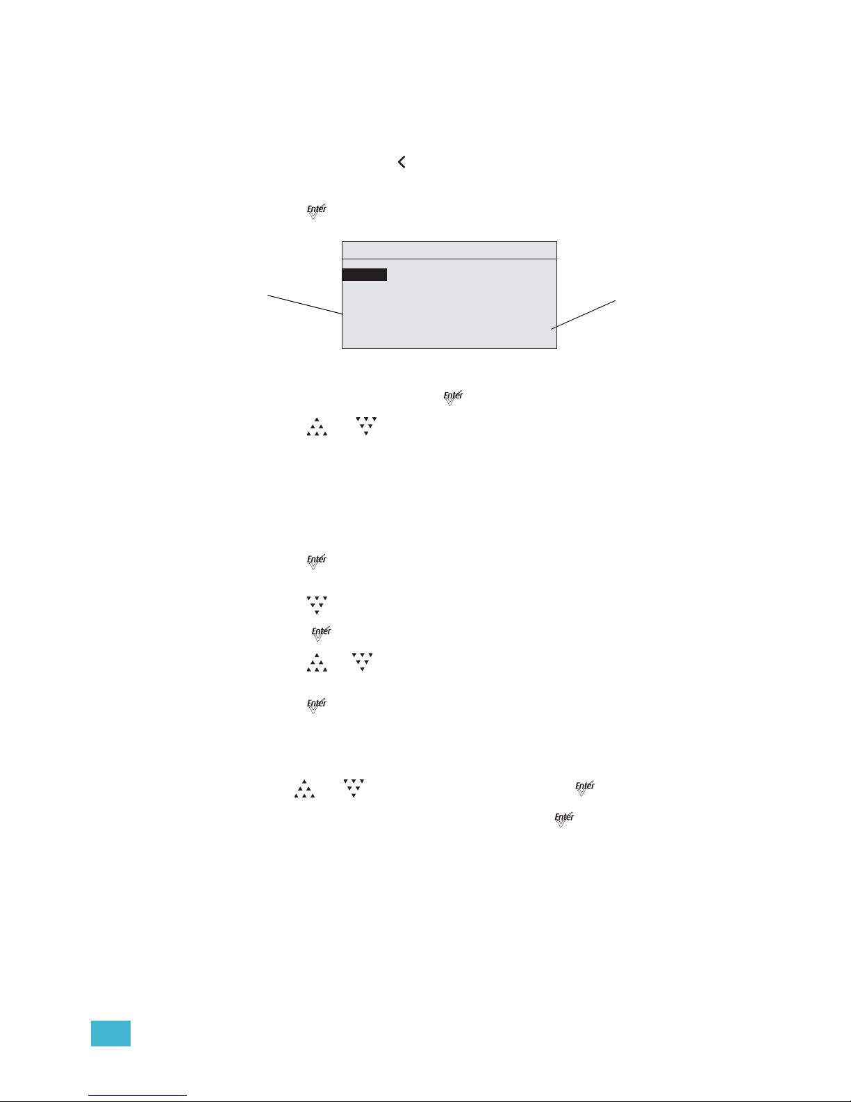
3 Operation 70
Test
Test is used to test the fixture and display its output values. Test overrides all other control
to the fixture. The action options are All Off, All On, Chase, and Ind Cntl (Individual control).
The default is All Off.
To exit the Test screen, press [] twice. The fixture will revert to its previous state.
Step 1: On the Diagnostics screen, scroll to Test.
Step 2: Press [].
Figure-3.34 Test Screen in Chase Mode.
Step 3: With Action selected, press [] to toggle between the options.
Step 4: Press [] or []to commit the option.
Chase
Chase automatically sequences through each LED color and starts each at 0% intensity
and steps up to 100% before moving to the next color. You can set the number of steps per
second for sequencing through all LED colors individually.
Step 1: On the Test screen, scroll to Action.
Step 2: Press [] until the Chase option displays.
The fixture begins to sequence through the LEDs.
Step 3: Press [] to select Chase.
Step 4: Press [[ ] to select the values.
Step 5: Press []or [] to set the number of steps per second.
The range is 10 to 20.
Step 6: Press [] to commit the value.
The percent of intensity is displayed for each color as the fixture sequences
through them.
Step 7: To stop the test, do one of the following.
• Press [] or [] to select Action and then press [] until All Off displays.
• Press [Back] to return to Action and then press []until All Off displays.
Diagnostics
Individual Con trol
Tes t
Action: Chase
Chase: 15 steps/sec
G O R A O R I
00 00 48 00 00 00 00
Brightness
LED series
Page 76
71 Source Four LED Profile v1.5.0 User Manual
Individual Control (Ind Cntl)
Use Individual Control to select each LED series and then adjust its intensity.
Step 1: On the Test screen, scroll to Action.
Step 2: Press []until the Ind Cntr option displays.
One of the LED series will illuminate.
Step 3: Press []to select the series.
Figure-3.35 Test Screen in Individual Control Mode.
Step 4: Press []or [] to set the intensity of the series.
Step 5: Press [] to move to the next series.
The value you entered for the first series is applied to the next series.
Step 6: Press [] or [] to change the intensity of the series.
Step 7: Press [] to return to Action.
Diagnostics
Individual Con trol
Tes t
Action: Ind Cntr
Chase: 15 steps/sec
G O R A O R I
56 00 00 00 00 00 00
Page 77
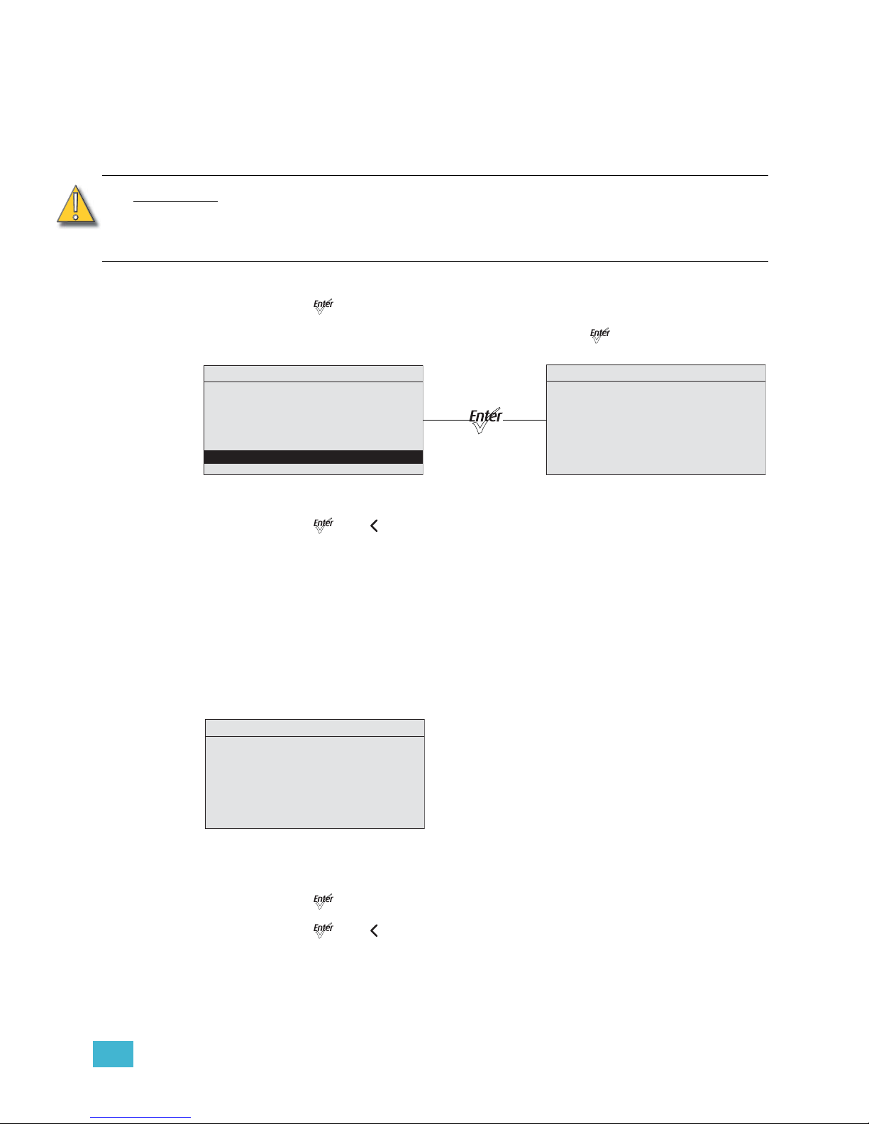
3 Operation 72
Recalibrate Fixture
Service technicians may use this option to calibrate the constant current driver electronics
for the LEDs. The calibration process goes through each series of LEDs, starting at 0
intensity and stepping up to 100%. The calibration is automatic and takes a few minutes.
During this time, do not exit the screen until it is complete.
Step 1: On the Diagnostics screen, scroll to Recalibrate Fixture.
Step 2: Press [].
Step 3: When asked if you are sure, select Yes and press [].
Figure-3.36 LED Calibration Screen with Calibration in Process.
Step 4: Press [] or [] to return to the Diagnostics screen.
About Fixture
The About screen displays the following information. This is a read-only screen.
• The software version number
• The fixture serial number
• The assigned fixture RDM number
• The color bias of the LED array
Figure-3.37 About Fixture screen.
Step 1: On the Diagnostics screen, scroll to About Fixture.
Step 2: Press [].
Step 3: Press [] or [] to return to the Diagnostics screen.
CAUTION:
This calibration process does not measure or recalibrate the light output of the LEDs.
Under normal use, it is not necessary to recalibrate the fixture, and doing so will likely
have no beneficial effect on fixture performance. It is therefore NOT recommended
to recalibrate the fixture without express instruction from an authorized technician.
LED Calibration
LED 1 .......Pass
LED 2 .......Pass
LED 3 .......Pass
LED 4 .......Working
LED 5 .......Working
LED 6 .......Working
LED 7 .......Working
Diagnostics
Recalibrate Fixture
This Will Calibrate
LED Array
Are You Sure?
Yes
No
About Fixture
RDM: 6574:12345678
Ve r: 1.5.0.0.0.05 (0)
Ser: 000021xxx
Desire Lustr+ 22
DMX START: 001
RDM Label
Page 78
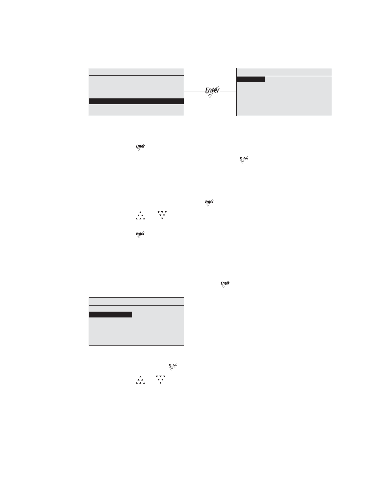
73 Source Four LED Profile v1.5.0 User Manual
Local Settings
The Local Settings menu gives you several options that affect the LCD and other functions
of the fixture.
Figure-3.38 Selecting Local Settings on the Advanced Menu.
Step 1: On the Advanced Menu, scroll to Local Settings.
Step 2: Press [].
Step 3: Scroll to any of the menu choices and press [].
Backlight
You can change the brightness of the LCD backlight. The brightness level is 10 to 100%.
The default is 100%.
Step 1: With Backlight selected, press []to select the value.
Step 2: Press [] or [] to set the desired brightness percentage. The effect can be
seen as you make the adjustment.
Step 3: Press [].
BLght time out
You can change the length of time the LCD backlight remains on after a UI button has been
pressed. The options are 30 seconds, 1 minute, 5 minutes, 15 minutes, and never. The
default is 1 minute.
Step 1: With BLght time out selected, press [].
Figure-3.39 Setting Backlight Timeout.
Step 2: Continue to press [] until the desired time is indicated.
Step 3: Press []or [] to commit the option.
Advanced Menu
DMX Settings
LED Settings
Presets and Sequences
Diagnostics
Local Settings
Copy All Settings
Local Settings
Backlight: 100%
BLght time out: 1 min
Language: English
Status Indicators: Off
OverTemp: Visible
Restore Defaults
Local Settings
Backlight: 100%
BLght time out: 1 min
Language: English
Status Indicators: Off
OverTemp: Visible
Restore Defaults
Page 79
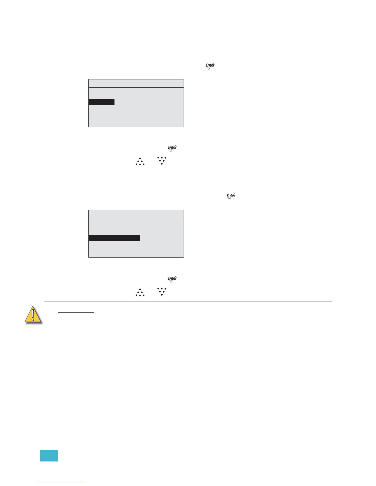
3 Operation 74
Language
Use this to select the language that is used for all menus. The options are English, Spanish,
French, and German. The default is English.
Step 1: With Language selected, press [].
Figure-3.40 Setting the Screen Language.
Step 2: Continue to press [] until the desired language is displayed.
Step 3: Press [] or [] to commit the option.
Status Indicators
You can turn the status indicators on or off. The default is on.
Step 1: With Status Indicators selected, press [].
Figure-3.41 Setting the Status Indicator display.
Step 2: Continue to press [] to toggle between ON and OFF.
Step 3: Press [] or [] to commit the option.
CAUTION:
Although it may be desirable in some applications to eliminate all stray light from the
back of the fixture, turning the Status Indicators OFF prevents them from
communicating potentially critical information. Use discretion when selecting the
OFF setting.
Local Settings
Backlight: 100%
BLght time out: 1 min
Language: English
Status Indicators: Off
OverTemp: Visible
Restore Defaults
Local Settings
Backlight: 100%
BLght time out: 1 min
Language: English
Status Indicators: Off
OverTemp: Visible
Restore Defaults
Page 80
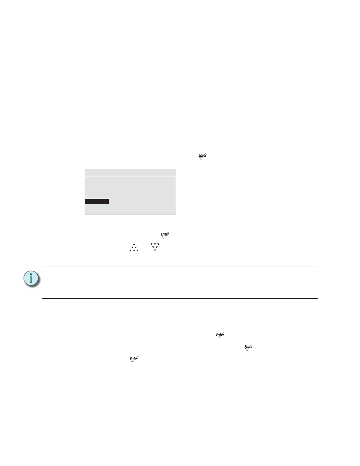
75 Source Four LED Profile v1.5.0 User Manual
OverTemp
You can change how an over-temperature situation is indicated in order to control stray
light.
Visible (Lustr+ and Studio HD)
The fixture produces a low-level, red light from the LED array, displays a warning message
on the LCD, turns on the LCD backlight, and turns on the error indicator light.
Visible (Daylight and Tungsten)
The fixture produces a low-level light from only some of the LEDs in the LED array, displays
a warning message on the LCD, turns on the LCD backlight, and turns on the error indicator
light.
Dark
The fixture turns off the LED array entirely and displays a warning message on the LCD
without turning on the LCD backlight.
Step 1: With OverTemp selected, press [].
Figure-3.42 Setting Over Temperature Indication.
Step 2: Continue to press [] to toggle between the two options.
Step 3: Press [] or []to commit the option.
For more information, see Thermal Shutdown Warning, page 46.
Restore Defaults
You can restore the fixture to the factory settings. This function clears all custom settings
including all changes to Presets and Sequences.
Step 1: With Restore Defaults selected, press [].
Step 2: When asked if you are sure, select Yes and press [].
Step 3: Press [].
Note:
When returning to normal operation, after the fixture has been in a shut-down status,
the LED array automatically transitions its output back to the current control signal
or stand-alone operation over a 10-second crossfade. There is no required reset
function once the fixture temperature returns to a safe level.
Local Settings
Backlight: 100%
BLght time out: 1 min
Language: English
Status Indicators: Off
OverTemp: Visible
Restore Defaults
Page 81
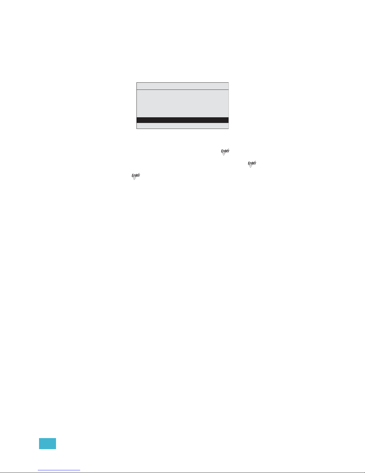
3 Operation 76
Copy All Settings
When DMX is not applied you can copy all, except DMX address, settings globally to all of
the other fixtures in the same data chain in one step. This includes everything from Presets
and Sequences to Quick Setups and Advanced options.
This feature is not available when DMX is applied to the fixture.
Figure-3.43 Copy All Settings on the Advanced Menu.
Step 1: With Copy All Settings selected, press [].
Step 2: When asked if you are sure, select Yes and press [].
Step 3: Press [].
Advanced Menu
DMX Settings
LED Settings
Presets and Sequences
Diagnostics
Local Settings
Copy All Settings
Page 82
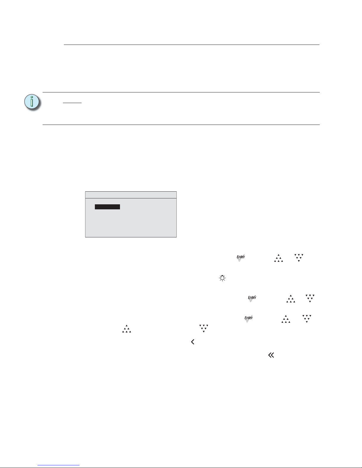
77 Source Four LED Profile v1.5.0 User Manual
Studio Settings
Lustr+ and Studio HD
The Studio profile produces only white light that is adjustable in brightness, white point, and
tint (green/magenta balance). The Studio profile can be operated in a stand-alone mode
from the user interface or can be controlled via DMX.
Operation From Home Status Screen (Studio Standalone)
When operating without an external control signal, the intensity of the white light can be
adjusted immediately and directly by pressing the UI buttons on the fixture while on the
home screen. In this setup, all the UI buttons change their functions from other setups.
Icons on the screen indicate which buttons to use for the settings.
When fixtures are connected together and there is no control signal, all adjustments that
you make on one fixture are automatically made on the connected fixtures.
Figure-3.44 Studio Status Home screen (Vivid, Lustr+, and Studio HD).
• To adjust the Intensity, select it in the menu and press [] and then [] or []. The
range is 0 to 100%.
• To immediately set the Intensity to 0, press the [] button. Pressing it again will return
it to the previously-set Intensity.
• To adjust the White Point, select it in the menu and press [] and then []or [].
The range is 2700 to 6500K.
• To adjust the Tint, press select it in the menu and press []and then [] or [].
Pressing [] increases magenta and []increases green.
• To return to the Main Menu, press [].
• To return to the Studio status screen from the Main Menu, press [].
Note:
Studio profile is the default Quick Setup for fixtures containing the Studio HD LED
array. Fixtures with other LED arrays may also be operated in Studio profile by
selecting this setting from Quick Setups or DMX Settings. Fixtures with Studio HD
LED arrays may also be operated in other setups.
Studio
Intensity:
System OK
STUDIO MODE
4/5 Intens ity
WhitePoint: 3200K
80%
100 %
Tin t:
Page 83
3 Operation 78
Studio DMX Control
When controlled via DMX, the first three channels adjust the output in the following order.
Channel 5 controls strobe.
When adjusting white point via DMX, the full gamut of 2700 to 6500K is available, but
common settings of 3200K and 5600K are quickly accessible at the lowest and highest
DMX values, respectively. The range of control on channel 2 is distributed as follows.
When adjusting tint via DMX, the range of control on channel 3 is distributed as follows.
Additional channels for other functions, such as strobe and Plus 7, can also be activated, if
desired, starting with channel 4.
Channel Output
1 Intensity (Brightness)
2 White Point
3Tint
5 Strobe
DMX Value White Point
000 3200K
001 to 254 Continuous adjustment from 2700 to 6500K
255 5600K
DMX Value Tint
000 Neutral white (at the specified white point)
001 Extreme green (approximately 2x plus green)
002 to 127 Moving from green toward neutral white
128 Neutral white
129 to 254 Moving from neutral white toward magenta
255 Extreme magenta (approximately 2x minus green)
Note:
When using DMX to control the fixture in Studio mode, the default data-loss behavior
is different than in other operational modes. If the DMX signal is lost, the fixture
automatically holds the last look forever (HLL-4ever) and this look persists through
infinite off/on power cycles, until the DMX signal is restored or the fixture settings are
adjusted manually via the User Interface.
Page 84
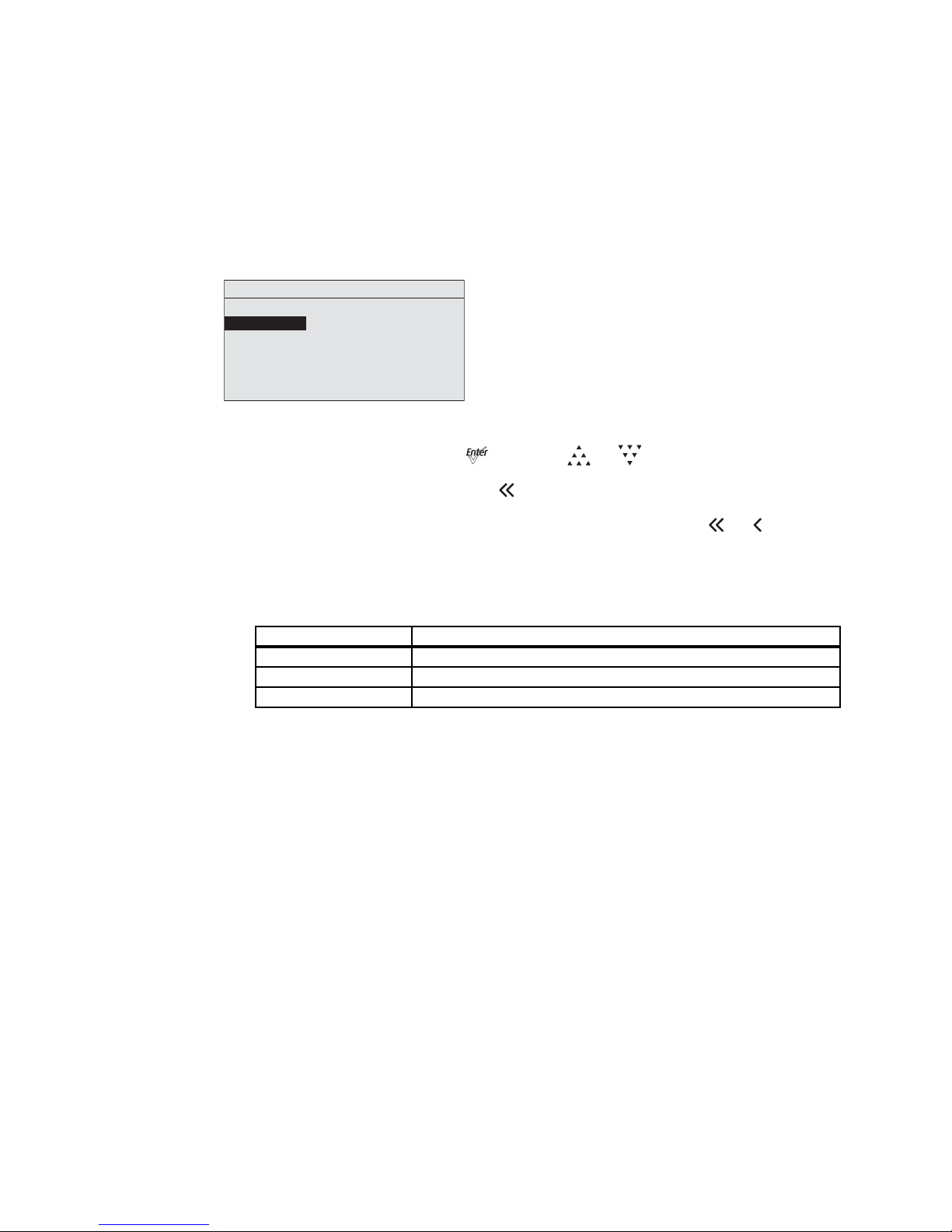
79 Source Four LED Profile v1.5.0 User Manual
Daylight and Tungsten
The Studio profile allows quick adjustment of Intensity. The Studio profile can be operated
in a stand-alone mode from the user interface or can be controlled via DMX.
Operation From Home Status Screen (Studio Standalone)
When operating without an external control signal, the quality of the white light can be
adjusted immediately and directly by pressing the UI buttons on the fixture while on the
home screen. In this setup, all the UI buttons change their functions from other setups.
Icons on the screen indicate which buttons to use for the settings.
Figure-3.45 Studio Status Home screen.
• To adjust the Intensity, press [] and then []or []. The range is 0 to 100%.
• To return to the Main Menu, press [].
• To return to the Studio status screen, from the Main Menu, press [], [], or allow
the UI to time out and automatically return to the status screen.
Studio DMX Control
When controlled via DMX, the channels adjust the following.
Channel Output
1 Intensity (Brightness)
2 Strobe
3Fan
Studio
Intensity: 100%
System OK
1/3 In t e ns i t y
STUDIO MODE
Page 85
3 Operation 80
Error Messages
When a system error is detected, a message displays on the home screen. The message
changes to reflect the specific error type. When multiple errors are detected, each error
message cycles, in increasing numerical order on the display for 1 second each. The
following table lists the error messages.
Error Message Description
LED Ambient Overtemp
The LED head ambient temp is too hot and has been shut down, let
fixture cool down
LED Ambient High The LED head ambient is getting hot. Let the fixture cool.
LED Ambient Low The LED head ambient is too cold. Improper operating conditions.
Color System Fail
Fixture does not have its color information loaded. Most likely
represents a hardware failure.
LED Over Temp A specific LED is over-temp and the fixture has been shut down.
Internal Temp High Fixture internal temp is too hot.
Power Budget Active The fixture is reducing the LED output due to hot temperatures.
Internal Overtemp
The internal temperature is too hot, the fixture has been shut down.
Let the fixture cool.
Configuration Error
The stored configuration has been compromised. The fixture will
return to a default configuration.
Page 86

81 Source Four LED Profile v1.5.0 User Manual
Software Updates
The software can be updated with UpdatorAtor Software. UpdatorAtor allows you to
remotely update the Source Four LED fixture. UpdatorAtor is installed on your computer
and connected from the computer to the fixture with a special cable. For more information,
contact ETC’s Technical service department.
ETC Technical Support
Any time, any day–15 minute response time—that’s our service commitment. ETC’s
Technical Service is unparalleled in the industry. With over 60 service employees
worldwide, not to mention our extensive Authorized Service Center network, we are
uniquely positioned to be able to help you anywhere, anytime. Call on our years of expertise
for help with any lighting situation. Our commitment is to make your day shine brighter.
Americas
608/831-4116
or toll-free in the U.S. at 800/688-4116
Europe
(+44) 20 8896 1000
Germany
(+49) 8024 4700-0
Asia
(+852) 2799 1220
Page 87
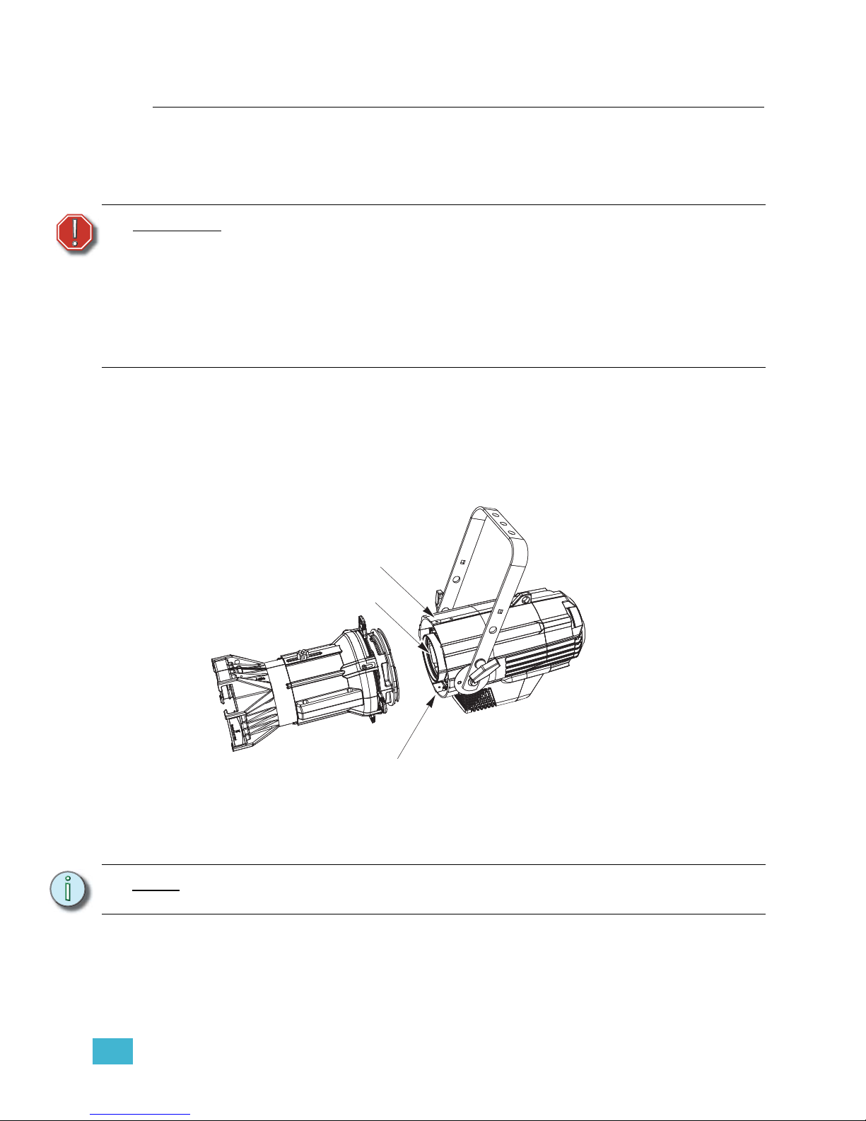
3 Operation 82
Routine Maintenance
To ensure optimum performance of your Source Four LED series fixture, you should
perform the following inspections and cleaning at least once a year. You may need to
inspect or clean the fixture more often, depending on the type and amount of use your
fixture experiences during the year.
Cleaning the Field Lens
The field lens is accessed by removing the shutter barrel from the light engine body.
Use a clean micro-fiber cloth to clean the lens. Isopropyl alcohol may be used on the cloth.
Do not spray the cleaning solution directly onto the lens or the interior of the fixture.
Step 1: Remove the retainer bolt and lens rotation knob.
Figure-3.46 Removing the shutter barrel to expose the field lens.
Step 2: Slide the electronics and lens out of the fixture.
Step 3: Use a clean, soft cloth as described above to clean the lens.
Step 4: Install and tighten the retainer bolt and lens rotation knob.
WARNING:
Allow fixture to cool down completely prior to cleaning.
Disconnect all power and DMX cables prior to cleaning.
Check for excessive dust or debris in the heat-dissipating fins around the
entire fixture enclosure. Clean using compressed air or a soft cloth. Keeping
the components of the enclosure clean facilitates efficient cooling and
extends LED longevity.
NEVER spray liquids into the fixture.
NEVER spray compressed air into a fixture that is powered-up.
Note:
Do not remove the field lens from the electronics or attempt to disassemble the field
lens. The lens or electronics contain no serviceable parts.
Retainer bolt
Field lens
Lens rotation knob
Page 88
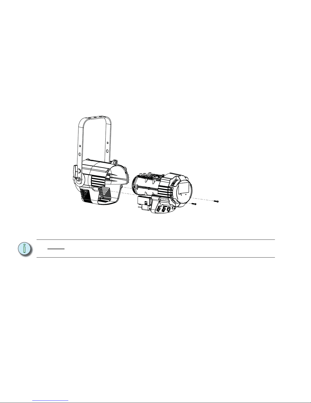
83 Source Four LED Profile v1.5.0 User Manual
Inspecting and Cleaning the Electronics
A can of compressed air or oil-free air from an air compressor set at a low setting can
be used to blow through the vent holes and remove dust or other debris from the
interior of the fixture. Dust buildup can cause overheating and premature shutdown.
Remove the secondary lenses (if used) and clean out any dust and debris. All
components, including the secondary lenses, can be cleaned using compressed,
oil-free air as described above or a clean micro-fiber cloth. Isopropyl alcohol may be
used.
Inspect all mounting hardware for wear and, if necessary, clean using compressed,
oil-free air or a soft, lint-free cloth.
Step 1: Use a 5/32" hex driver to remove the two screws that secure the back of the
electronics to the housing.
Figure-3.47 Electronics pulled out of housing.
Step 2: Slide the electronics and lens assembly out of the housing.
Step 3: While the electronic component body is separated from the housing, visually
inspect the interior of the body and ensure there is no dust build up on the
components. If there is, use canned compressed air or oil-free air from an air
compressor set at a low setting to remove dust or other debris from the interior
of the fixture.
Step 4: To reassemble, align the mating groves in the shutter barrel with the clips on the
electronics assembly and join the two.
Step 5: Install and tighten the hex head screws.
Note:
Do not remove the field lens from the electronics or attempt to disassemble the field
lens. The lens contains no serviceable parts.
Page 89
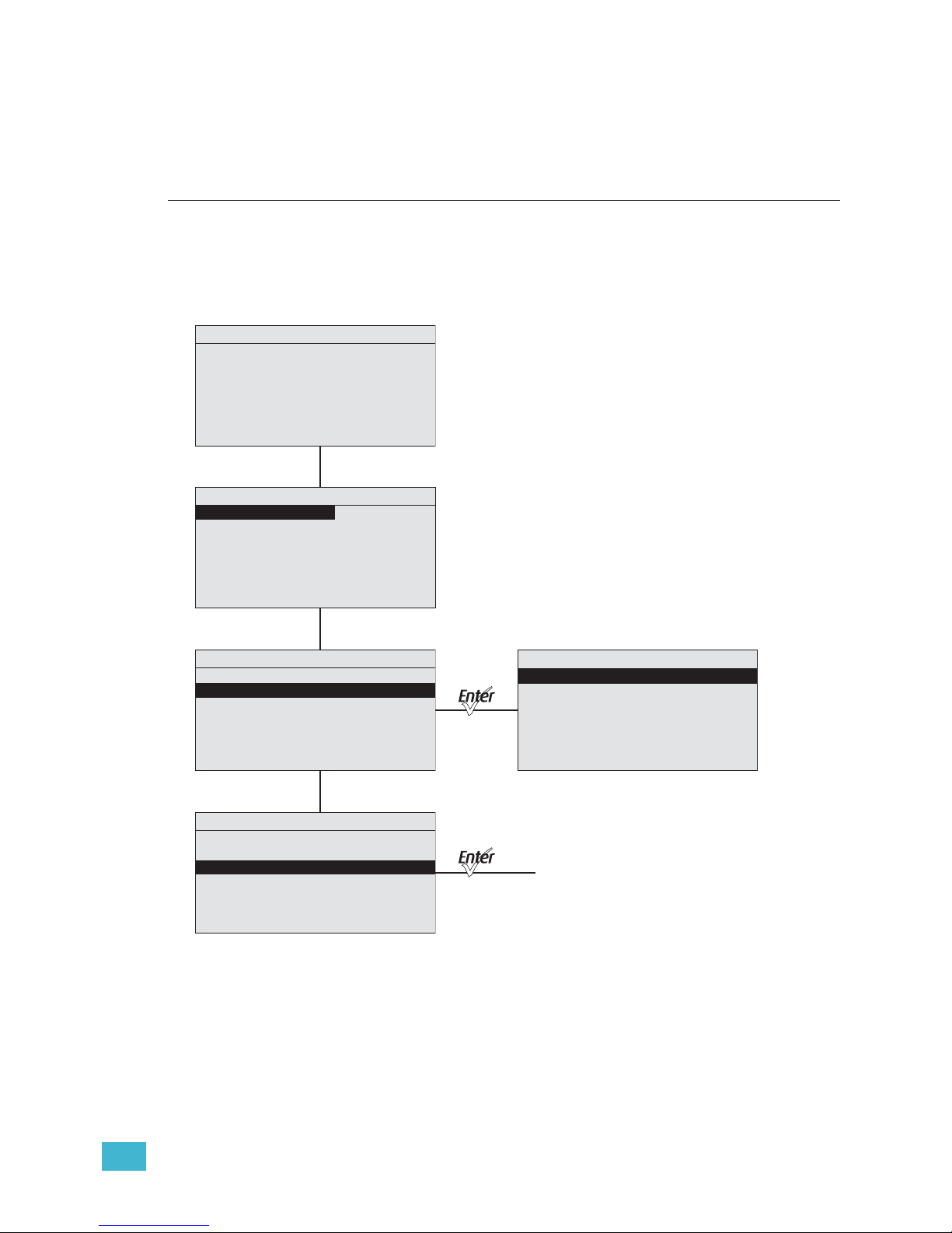
A Menu Flow Chart 84
Appendix A
Menu Flow Chart
The following illustrations show each of the menus that are displayed on the Source Four
LED fixture LCD and the path to each one.
Home and Main Menus (Lustr+ and Studio HD)
To Advanced
Menu
Main Menu
DMX Start Address: 001
Quick Setups
Advanced Settings
General
HSI Reg Stnd –– Str
No Sequence is Active
4/5 Intens ity
Master
System OK
No Preset is Active
Main Menu
DMX Start Address: 001
Quick Setups
Advanced Settings
Quick Setups
*General
Stage
High Impact
Studio
2/15 Hue Fine
XT Architectural
Main Menu
DMX Start Address: 001
Quick Setups
Advanced Settings
Page 90
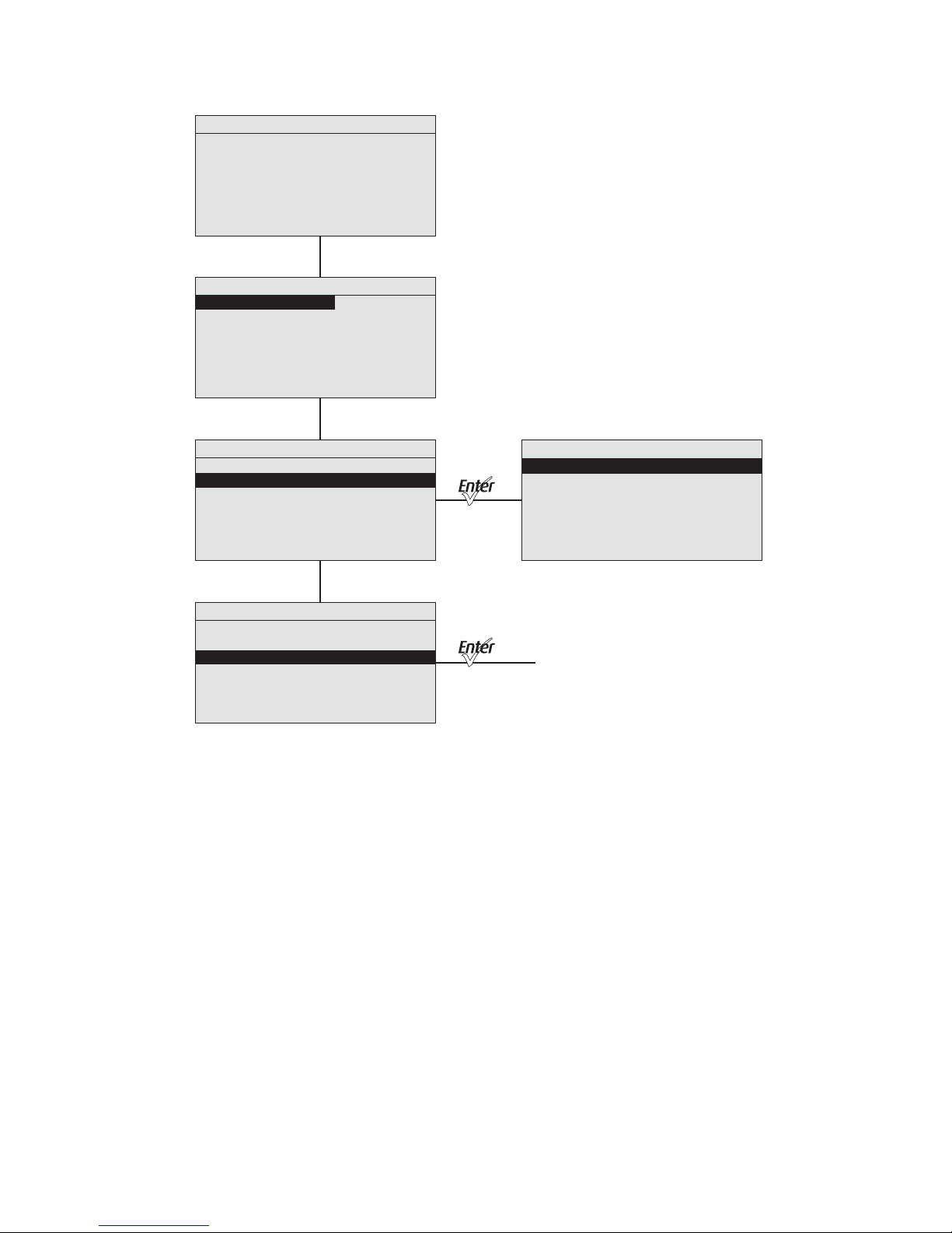
85 Source Four LED Profile v1.5.0 User Manual
Home and Main Menus (Daylight and Tungsten)
To Advanced
Menu
Main Menu
DMX Start Address: 001
Quick Setups
Advanced Settings
Main Menu
DMX Start Address: 001
Quick Setups
Advanced Settings
Main Menu
DMX Start Address: 001
Quick Setups
Advanced Settings
Quick Setups
*Studio
Stage
1/3 Intensity
Single Channel
Stage
Dir Reg Stnd –– Str
No Sequence is Active
1/3 In t e ns i t y
Master
System OK
No Preset is Active
Page 91
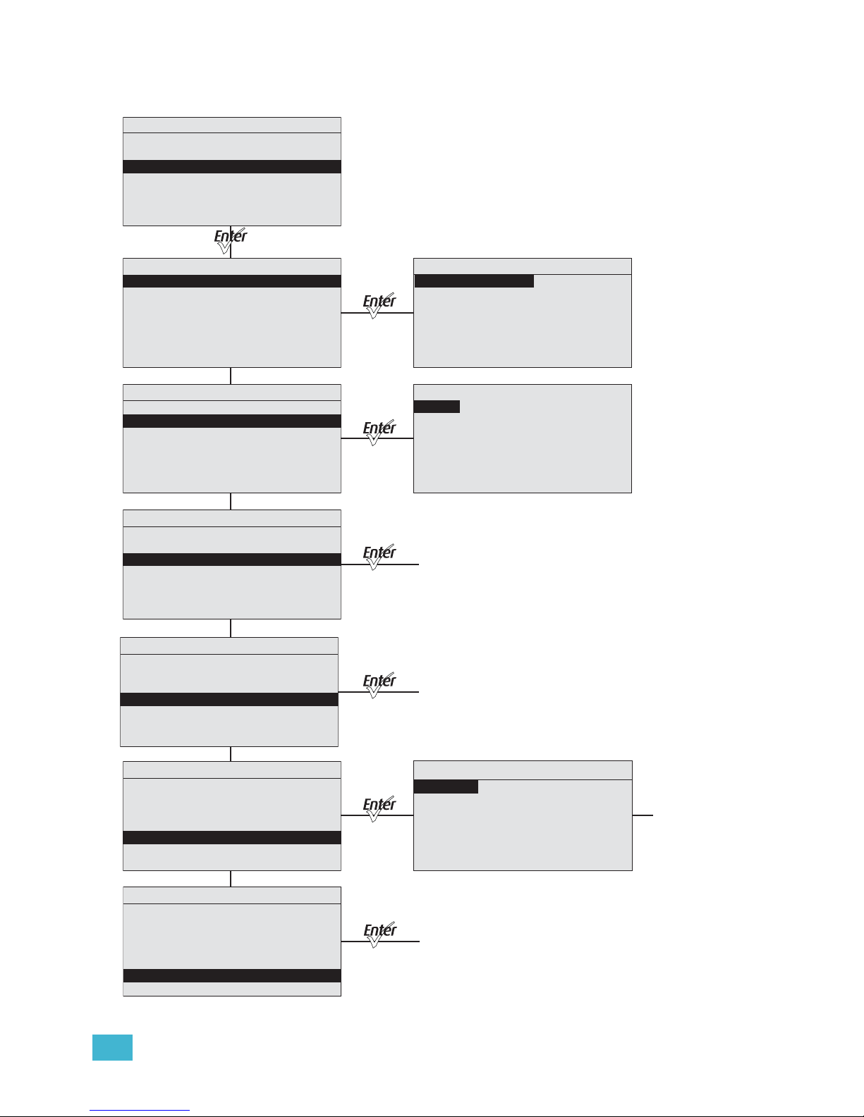
A Menu Flow Chart 86
Advanced Menu (Lustr+ and Studio HD)
Advanced Menu
DMX Settings
LED Settings
Presets and Sequences
Diagnostics
Local Settings
Copy All Settings
DMX Settings
DMX Start Address: 101
DMX Profile: HSIC
Strobe: Enabled
Data Loss: Instant
Plus Seve n: En abled
DMX Profile: 6 chan
1/15 Hue Coarse
Advanced Menu
DMX Settings
LED Settings
Presets and Sequences
Diagnostics
Local Settings
Copy All Settings
LED Settings
Output: Regulated
Curve: Standard
Output Freq: 1200
Red Shift: Off
White Point: 3200K
Advanced Menu
DMX Settings
LED Settings
Presets and Sequences
Diagnostics
Local Settings
Copy All Settings
Main Menu
DMX Start Address: 001
Quick Setups
Advanced Settings
Advanced Menu
DMX Settings
LED Settings
Presets and Sequences
Diagnostics
Local Settings
Copy All Settings
Local Settings
Backlight: 100%
BLght time out: 1 min
Language: English
Status Indicators: Off
OverTemp: Visible
Restore Defaults
To Presets and
Sequenses Menu
To Diagnostics
Menu
To
Confirmation
Advanced Menu
DMX Settings
LED Settings
Presets and Sequences
Diagnostics
Local Settings
Copy All Settings
*
*
*
*
*
*
Copy All Settings appears only when DMX is not present.
Advanced Menu
DMX Settings
LED Settings
Presets and Sequences
Diagnostics
Local Settings
Copy All Settings
To
Confirmation
***Press the Light Bulb button
at any time for quick
access to the Presets and
Sequences Menu.
Page 92
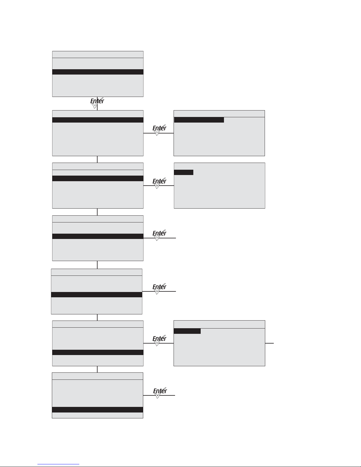
87 Source Four LED Profile v1.5.0 User Manual
Advanced Menu (Daylight and Tungsten)
Advanced Menu
DMX Settings
LED Settings
Presets and Sequences
Diagnostics
Local Settings
Copy All Settings
Advanced Menu
DMX Settings
LED Settings
Presets and Sequences
Diagnostics
Local Settings
Copy All Settings
Advanced Menu
DMX Settings
LED Settings
Presets and Sequences
Diagnostics
Local Settings
Copy All Settings
Main Menu
DMX Start Address: 001
Quick Setups
Advanced Settings
Advanced Menu
DMX Settings
LED Settings
Presets and Sequences
Diagnostics
Local Settings
Copy All Settings
Local Settings
Backlight: 100%
BLght time out: 1 min
Language: English
Status Indicators: Off
OverTemp: Visible
Restore Defaults
To Presets and
Sequenses Menus
To Diagnostics
Menu
To
Confirmation
Advanced Menu
DMX Settings
LED Settings
Presets and Sequences
Diagnostics
Local Settings
Copy All Settings
Advanced Menu
DMX Settings
LED Settings
Presets and Sequences
Diagnostics
Local Settings
Copy All Settings
To
Confirmation
DMX Settings
DMX Start Address: 101
DMX Profile: Direct
Strobe Mode: Enabled
Data Loss: Instant
Fan Mode: Auto
1/15 I n te ns i t y
LED Settings
Output: Regulated
Curve: Standard
Output Freq: 1200
*
*
*
*
*
*
Copy All Settings appears only when DMX is not present.
Page 93
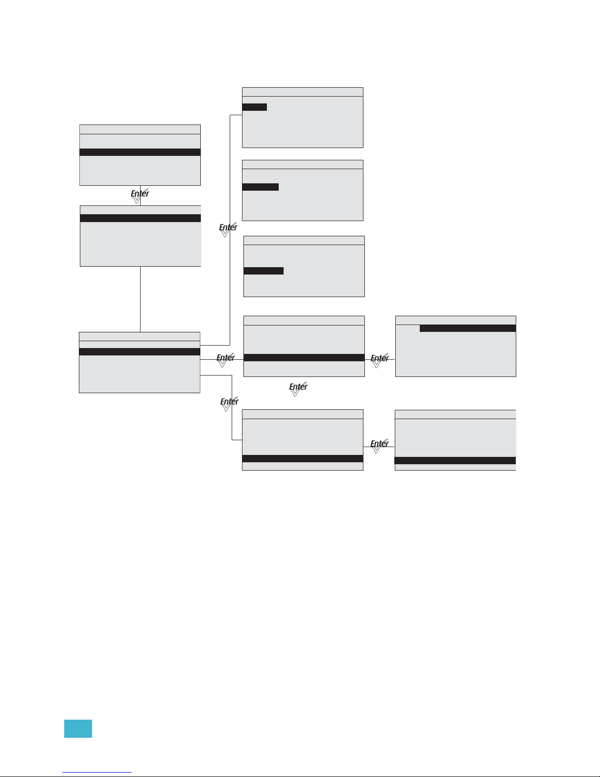
A Menu Flow Chart 88
Presets Menu (Lustr+ and Studio HD)
Presets and Sequences
Focus: Off
Presets
Sequences
Quick Color
Preset 1 is Active
No Sequence is Active
Advanced Menu
DMX Settings
LED Settin gs
Presets and Sequences
Diagn ostic s
Local Settings
Copy All Settings
Presets and Sequences
Focus: Off
Presets
Sequences
Quick Color
Preset 1 is Active
No Sequence is Active
Presets
Preset: * 23
Status: Active
Fade Time: 00:02
Delay Time: 00:00
Edit
Copy to Other Fixture
Presets
Preset: * 23
Status: Active
Fade Time: 00:02
Delay Time: 00:00
Edit
Copy to Other Fixture
Presets
Preset: * 23
Status: Active
Fade Tim e: 00:02
Delay Time: 00:00
Edit
Copy to Other Fixture
Presets
Preset: * 23
Status: Active
Fade Time: 00:02
Delay Time: 00:00
Edit
Copy to Other Fixture
Preset 23 Edit
Color:
Hue Course: 0
Hue Fine: 0
Sat: 0
Int: 100%
Strobe: 255
Save Changes
White
Presets
Preset: * 23
Status: Active
Fade Time: 00:02
Delay Time: 00:00
Edit
Copy to Other Fixture
Copy Preset
This Will Copy
Preset Data
From This Fixture to
All other Fixtures
Are You Sure?
Yes
No
* Copy All Settings appears only
when DMX is not present.
Page 94
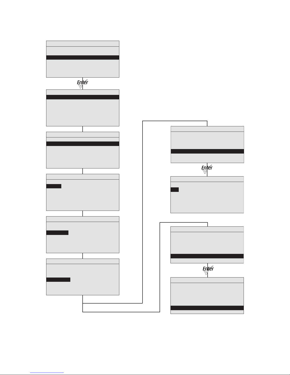
89 Source Four LED Profile v1.5.0 User Manual
Presets Menu (Daylight and Tungsten)
Presets and Sequences
Focus: Off
Presets
Sequences
Preset 1 is Active
No Sequence is Active
Advanced Menu
DMX Settings
LED Settings
Presets and Sequences
Diagnostics
Local Settings
Copy All Settings
Presets and Sequences
Focus: Off
Presets
Sequences
Preset 1 is Active
No Sequence is Active
Presets
Preset: * 23
Status: Active
Fa d e Ti m e: 0 0:02
Delay Time: 00:00
Edit
Copy to Other Fixture
Presets
Preset: * 23
Status: Active
Fade Time: 00:02
Delay Time: 00:00
Edit
Copy to Other Fixture
Presets
Preset: * 23
Status: Active
Fade Time: 00:02
Delay Time: 00:00
Edit
Copy to Other Fixture
Presets
Preset: * 23
Status: Active
Fa d e Ti m e: 00:02
Delay Time: 0 0:0 0
Edit
Copy to Other Fixture
Copy Preset
This Will Copy
Preset Data
From This Fixture to
All other Fixtures
Are You Sure?
Yes
No
Preset 23 Edit
Preset: 23
Int: 100%
Strobe: 0
Save Changes
Presets
Preset: * 23
Status: Active
Fade Time: 00:02
Delay Time: 00:00
Edit
Copy to Other Fixture
Save DMX as Preset
* Copy All Settings appears only when DMX is not present.
Page 95
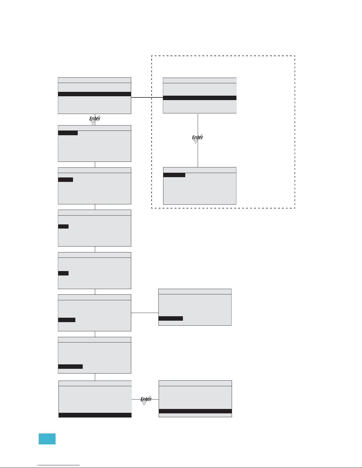
A Menu Flow Chart 90
Sequences Menu (all fixture types) and
Quick Color Menu (Lustr+ and Studio HD only)
If Preset is
set to ‘0’
Sequences
Sequence: *3
Action: Not Active
Rate: 100%
Step: 01
Preset: 1
Link Time: 00:02
Copy to Other Fixture
Sequences
Sequence: *3
Action: Not Active
Rate: 100%
Step: 01
Preset: 1
Link Time: 00:02
Copy to Other Fixture
Sequences
Sequence: * 3
Action: Not Active
Rate: 100%
Step: 01
Preset: 1
Link Time: 00:02
Copy to Other Fixture
Sequences
Sequence: * 3
Action: Not Active
Rate: 100%
Step: 01
Preset: 1
Li n k T ime: 0 0:02
Copy to Other Fixture
Sequences
Sequence: * 3
Status: Active
Rate: 100%
Step: 01
Preset: 0
End State: Loop
Copy to Other Fixture
Sequences
Sequence: * 3
Status: Active
Rate: 100%
Step: 01
Preset: 0
End State: Loop
Copy to Other Fixture
Presets and Sequences
Focus: Off
Presets
Sequences
Quick Color
Preset 1 is Active
No Sequence is Active
Sequences
Sequence: *3
Action: Not Active
Rate: 100%
Step: 01
Preset: 1
Link Time: 00:02
Copy to Other Fixture
Sequences
Sequence: *3
Action: Not Active
Rate: 100%
Step: 01
Preset: 1
Link Time: 00:02
Copy to Other Fixture
Copy Sequence
This Will Copy
Preset Data
From This Fixture to
All other Fixtures
Are You Sure?
Yes
No
Presets and Sequences
Focus: Off
Presets
Sequences
Quick Color
Preset 1 is Active
No Sequence is Active
Quick Color
Intensity: 0%
Color: LIT BLUE
Press the Light Bulb button
for immediate access to
the Quick Color menu.
The Quick Color menu is only available on
Lustr+ and Studio HD xtures
Page 96
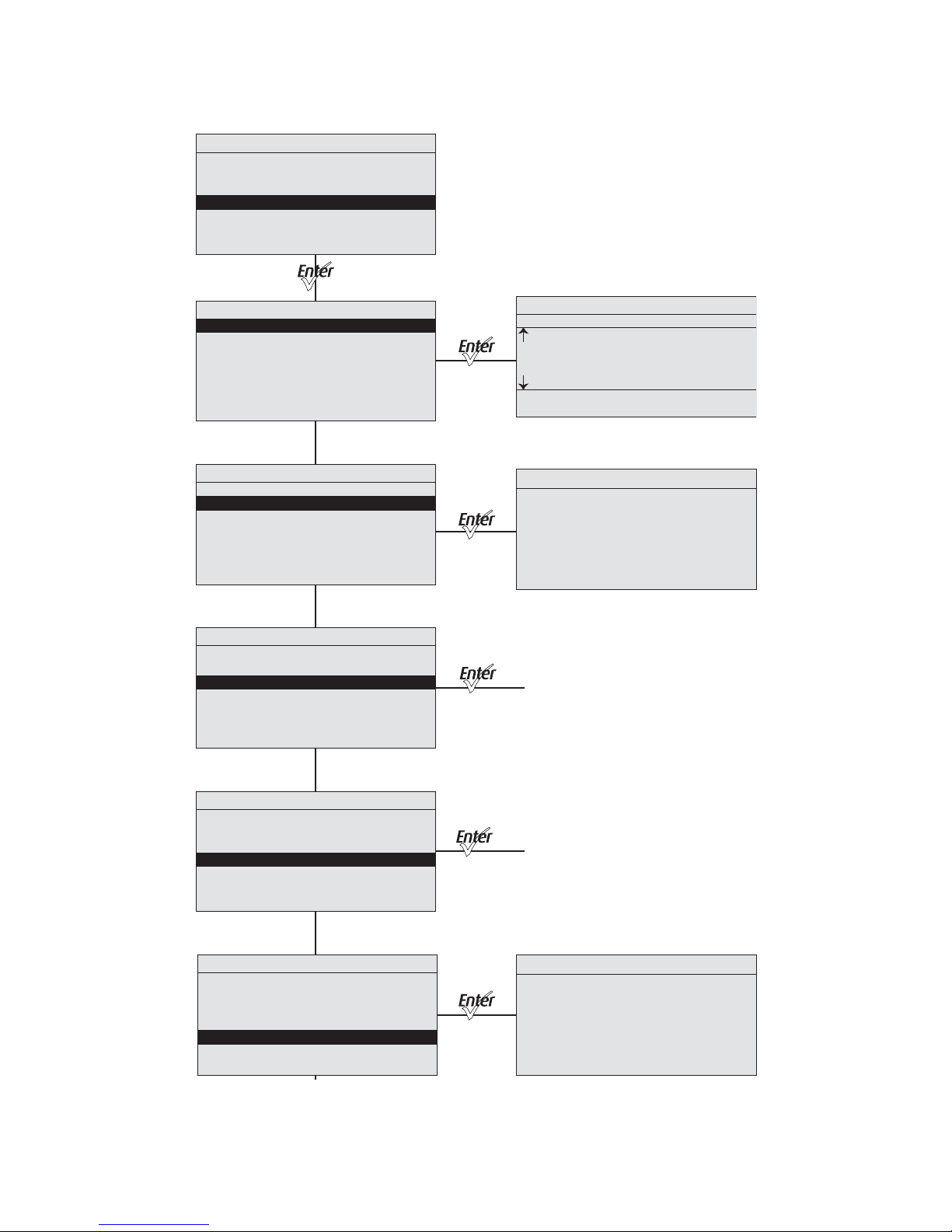
91 Source Four LED Profile v1.5.0 User Manual
Diagnostics Menu
About Fixture
RDM: 6574:12345678
Ve r: 1.4.1.0.0.2 0 (1)
Ser: 000021xxx
Desire Vivid 22
DMX START: 001
RDM Label
Diagnostics
Current DMX In
Network Statistics
Tes t
Recalibrate Fixture
About Fixture
Current DMX In
DMX Ch Level
2 107
3 14
4 82
5 0
G O R A O R I
11 02 00 10 00 00 01
Advanced Menu
DMX Settings
LED Settings
Presets and Sequences
Diagnostics
Local Settings
Copy All Settings
Diagnostics
Breaks: 15490
Network Statistics
Overruns: 0
Received: 47835
Bad Starts: 0
DMX Starts: 27120
RDM Starts: 0
Diagnostics
Current DMX In
Network Statistics
Tes t
Recalibrate Fixture
About Fixture
Diagnostics
Current DMX In
Network Statistics
Tes t
Recalibrate Fixture
About Fixture
Diagnostics
Current DMX In
Network Statistics
Tes t
Recalibrate Fixture
About Fixture
Diagnostics
Current DMX In
Network Statistics
Tes t
Recalibrate Fixture
About Fixture
To Te st
To Recalibrate
Fixture
Page 97
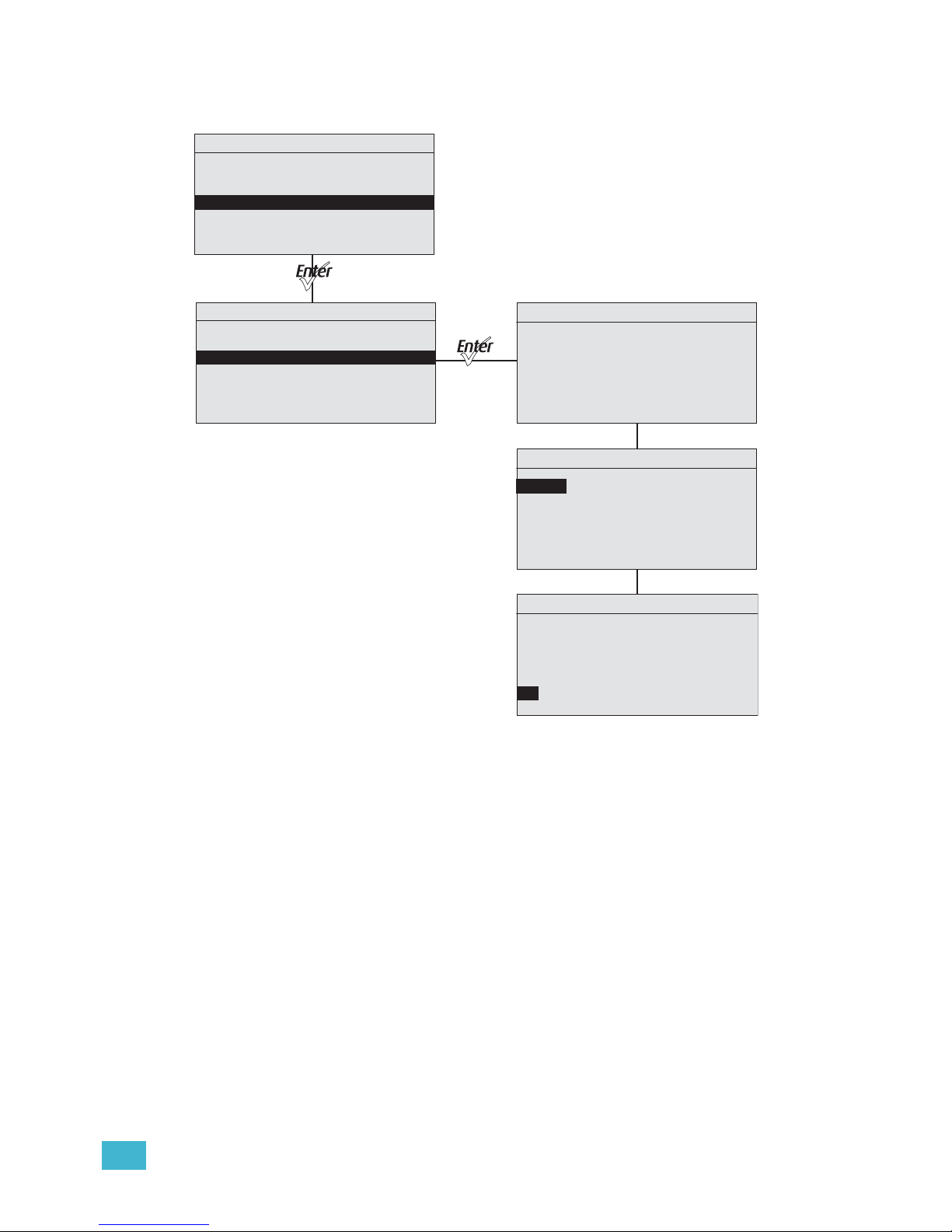
A Menu Flow Chart 92
Diagnostics Test
Advanced Menu
DMX Settings
LED Settings
Presets and Sequences
Diagnostics
Local Settings
Diagnostics
Current DMX In
Network Statistics
Tes t
Recalibrate Fixture
About Fixture
Diagnostics
Individual Con trol
Tes t
Action: Chase
Chase: 15 steps/sec
G O R A O R I
00 00 48 00 00 00 00
Diagnostics
Individual Con trol
Tes t
Action: Ind Cntr
Chase: 15 steps/sec
G O R A O R I
56 00 00 00 00 00 00
Diagnostics
Individual Con trol
Tes t
Action: Chase
Chase: 15 steps/sec
G O R A O R I
00 00 48 00 00 00 00
Page 98
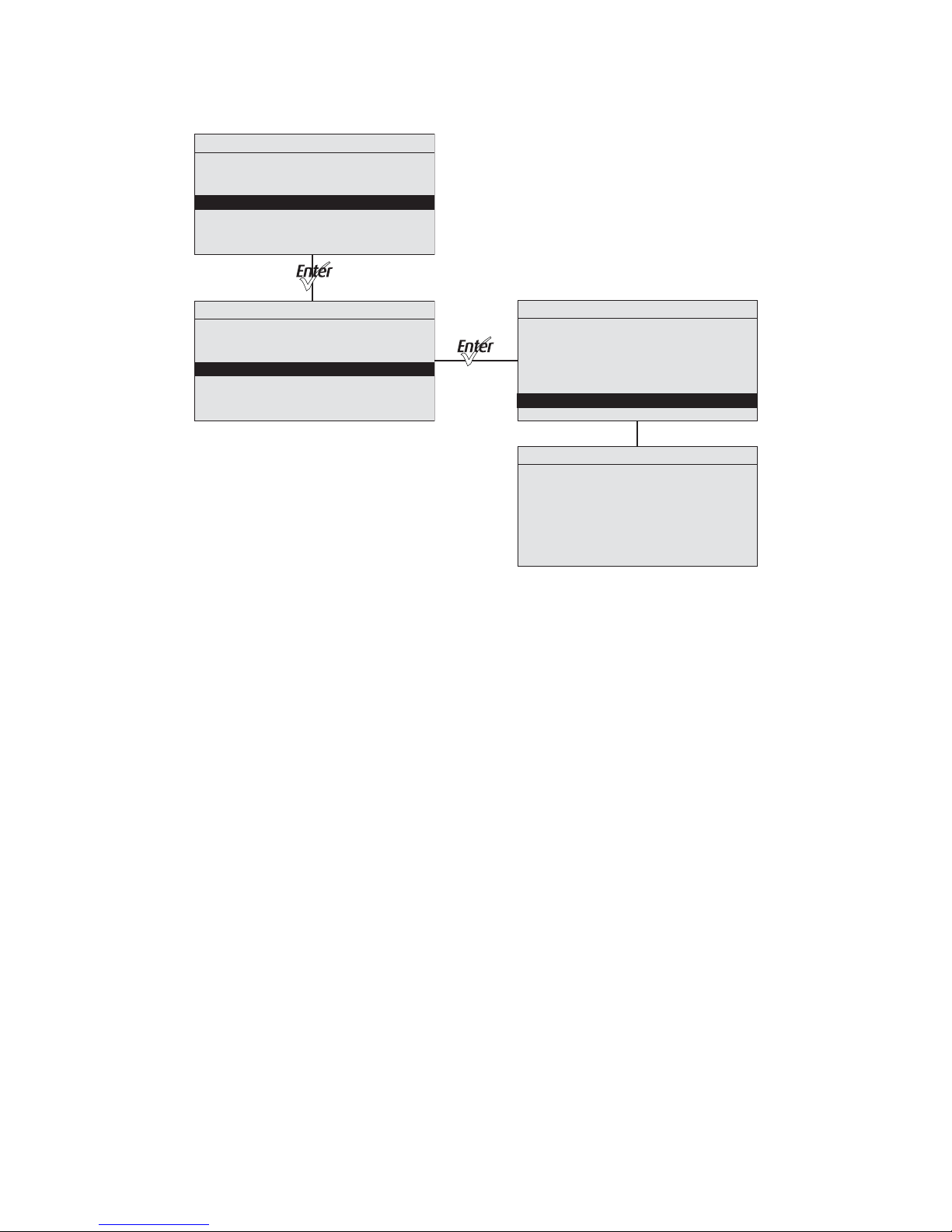
93 Source Four LED Profile v1.5.0 User Manual
Diagnostics Recalibrate Fixture
Advanced Menu
DMX Settings
LED Settings
Presets and Sequences
Diagnostics
Local Settings
Diagnostics
Current DMX In
Network Statistics
Tes t
Recalibrate Fixture
About Fixture
Diagnostics
Recalibrate Fixture
This Will Calibrate
LED Array
Are You Sure?
Yes
No
LED Calibration
LED 1 .......Pass
LED 2 .......Pass
LED 3 .......Pass
LED 4 .......Working
LED 5 .......Working
LED 6 .......Working
LED 7 .......Working
Page 99

A Menu Flow Chart 94
Page 100

Corporate Headquarters
3031 Pleasant View Road, P.O. Box 620979, Middleton, Wisconsin 53562-0979 USA Tel +608 831 4116 Fax +608 836 1736
London, UK
Unit 26-28, Victoria Industrial Estate, Victoria Road, London W3 6UU, UK Tel +44 (0)20 8896 1000 Fax +44 (0)20 8896 2000
Rome, IT
Via Pieve Torina, 48, 00156 Rome, Italy Tel +39 (06) 32 111 683 Fax +44 (0) 20 8752 8486
Holzkirchen, DE
Ohmstrasse 3, 83607 Holzkirchen, Germany Tel +49 (80 24) 47 00-0 Fax +49 (80 24) 47 00-3 00
Hong Kong Rm 1801, 18/F, Tower 1 Phase 1, Enterprise Square, 9 Sheung Yuet Road, Kowloon Bay, Kowloon, Hong Kong Tel +852 2799 1220 Fax +852 2799 9325
Service:
(Americas) [email protected]
(UK) [email protected] (DE) [email protected]
(Asia) [email protected]
Web:
www.etcconnect.com
Copyright © 2013 ETC. All Rights Reserved. Product information and specifications subject to change.
7460M1200-1.5.0
Rev A Released 2013-09
ETC intends this document to be provided in its entirety.
 Loading...