

ETC Source Four HID jr, Source Four HID jr Zoom User Manual
Source Four
™
HID jr and Source Four
™
HID jr Zoom
UL/cUL User Guide
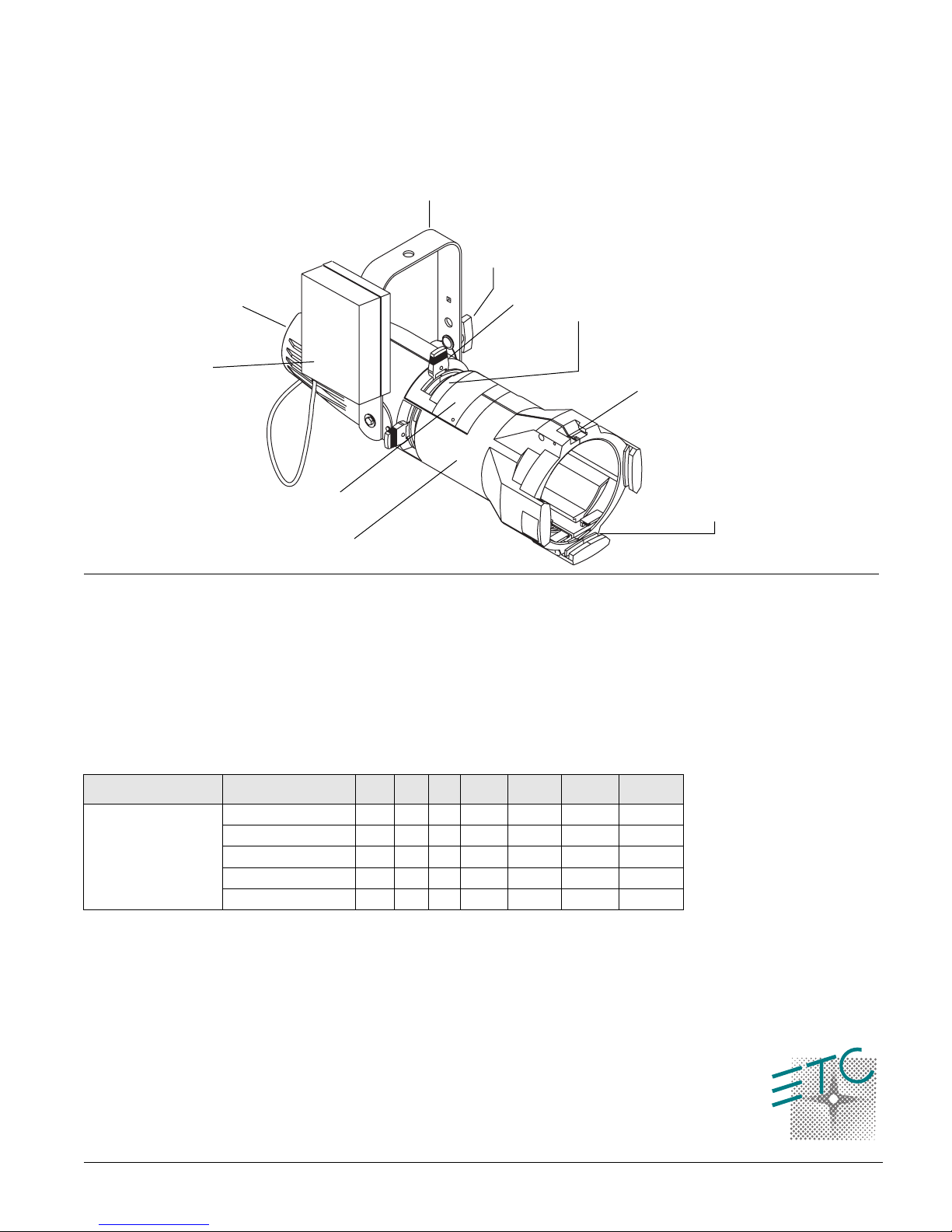
Yoke
Yoke
locking knob
Lamp housing
Ballast
Drop-in
iris cover
Barrel
Shutter
Pattern
holder slot
Lamp type and general information:
Do not use lamps other than the following lamp type in Source Four HID jr/Zoom
fixtures. Use of lamps other than specified below will void UL/cUL safety
compliance and your warranty.
•
Source Four HID jr/Zoom is suitable for damp locations
•
Yoke Can be canopy mounted
•
No recessed mounting
Caution!
ballast and void warranty.
Lamp Type
Ceramic Metal Halide
Source Four HID jr/Zoom is NOT dimmable. Dimming will damage the
Manufacturing Codes Watt s Base Bulb LCL Ave. Hrs. Initial
lumens
CDM-T 150W/830 150 G12 T6 56mm 9000 14000 3000ºK
CDM-T 150W/942 150 G12 T6 56mm 9000 12700 4000ºK
MD150T6/U/G12/830 150 G12 T6 56mm 9000 14000 3000ºK
MBI150/T/30 150 G12 T7 57mm 6000 11500 3000ºK
MBI150/T/40 150 G12 T7 57mm 6000 11250 4000ºK
Gel frame
retaining clip
Gel frame holder
Color temp
Table 1:
HID lamp reference
Ballast information
Caution!
•
Acceptable voltage is 120V (+/- 10%) 50/60HZ only
•
Operating current of 1.5 Amps
•
Inrush current of <14 Amps
•
Room ambient temperature should not exceed 104ºF (40ºC)
•
Lamp ignition voltage is 4.5Kv, non-hot restrike
•
Ballast case temperature should not exceed 167ºF (75ºC)
•
The ballast is attached to the Source Four HID jr/Zoom yoke by two screws, nonremotable
The Source Four HID jr/Zoom cannot be dimmed.
Source Four™ HID jr and Source Four™ HID jr Zoom • 1
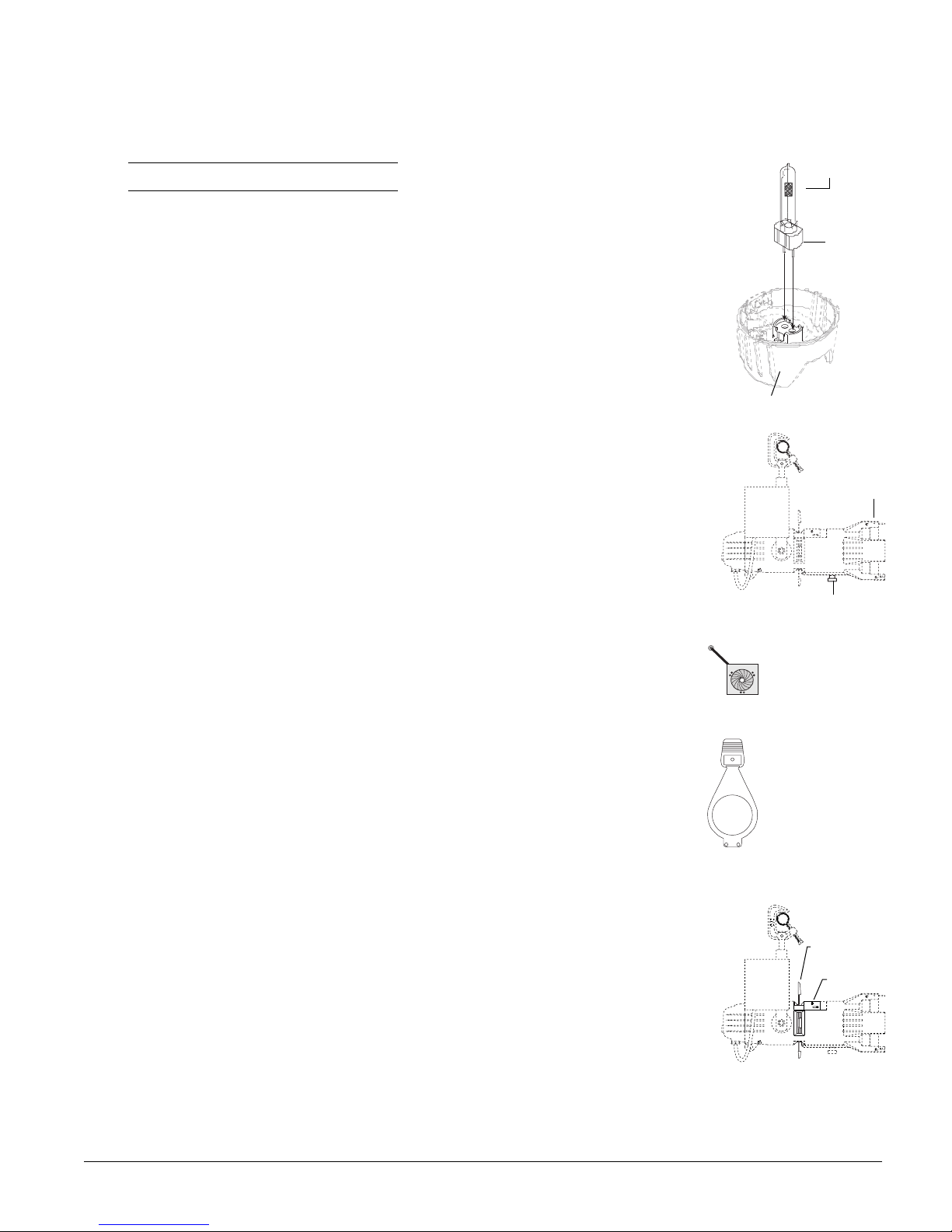
HPL lamp
Lamp
Lamp housing
base
Figure 1
Installing or replacing the lamp
The lamp must be installed before you use the fixture.
Note:
Verify that the lamp you intend to install is correct.
Replace the lamp if it becomes damaged or thermally deformed.
WARNING!
Disconnect power to the Source Four HID jr/Zoom before installing the lamp.
1.
2.
Loosen the knurled bolt on the back of the lamp housing and pull the housing straight out.
Holding the lamp by the base, remove the lamp from its box.
3.
Note:
Let lamp cool before replacing.
To avoid premature lamp failure, do not touch the lamp glass. If you do touch the
lamp, clean it carefully with rubbing alcohol and a clean, lint-free cloth before
operation.
4.
Insert lamp base into socket assembly as show in
Push down on the lamp base until the lamp seats firmly.
5.
Caution!
Reinstall the lamp housing by aligning the bolt hole and tightening the knurled bolt.
6.
Improperly installed lamps cause premature lamp failure and socket problems.
Figure 1
.
Focusing the beam
On a fixed field angle Source Four jr/Zoom, with a 26°, 36° or 50° lens, adjust the lens position to
focus the edge of the beam. On a Source Four HID jr Zoom, adjust the position of both lenses to
set the beam's spread and to focus the edge of the beam. The Zoom lenses give you a range from
25° to 50°.
Loosen the beam focus knob(s) on the underside of the barrel. See
1.
2.
Slide the lens(es) forward or backward to achieve the desired beam edge.
Once the fixture is focused, tighten the beam focus knob(s).
3.
Figure 2
.
Shaping the beam
You may shape the beam with the shutters, a pattern, or an optional drop-in iris (ETC part
#7062A1011). See
Figure 3
.
T
EC
Color frame
Beam focus knob
Iris
(ETC part # 7062A1011)
Figure 3
Figure 2
Pattern projection
The pattern holder slot is on the top side of the barrel, immediately in front of the shutters. It
accommodates the M-size pattern holder shown in
Figure 4
. The M-size pattern holder’s handle
should bend away from the shutter handle at a 30° angle. If your pattern holder’s handle is straight,
you may bend it far enough to not interfere with the action of the shutter handle.
Use an optional donut (ETC part #7060A1037) in the accessory holder to enhance pattern
projection.
Drop-in iris slot
The drop-in iris slot is on the top side of the front barrel, immediately in front of the pattern holder
slot. See
screws prevents light leakage and retains the iris assembly. To install an iris, follow these steps.
Figure 5
. When it is not in use, a small sheet metal cover secured with two crosshead
Caution!
1.
Use a Phillips screwdriver to loosen the screws on the drop-in iris slot cover. Do not
remove the screws.
2.
Slide the cover completely forward, exposing the slot.
Insert the iris. The flat side must be toward the shutters and the iris handle should extend
3.
out of slot.
4.
Slide the slot cover back toward the shutters until it meets the iris handle. Leave enough
Be certain the fixture is not hot before installing the iris.
space to move the iris handle. Tighten the screws.
M-size pattern holder
(ETC part # 7062A1010)
Figure 4
TE C
Pattern holder slot
Drop-in
iris slot
Figure 5
2 • Source Four™ HID jr and Source Four™ HID jr Zoom
 Loading...