

Page 1
CE Source Four jr &
CE Source Four jr Zoom
User manual
Gebrauchsanleitung
Manuel d’utilisation
Manual del usuario
Page 2
DECLARATION OF CONFORMITY
We, Electronic Theatre Controls, Europe Limited
Unit 5, Victoria Industrial Estate, London W3 6UU United Kingdomdeclare under sole
responsibility that the product
Product name: CE Source Four jr, CE Source Four jr Zoom
Product type/model: 7062A1201, 7062A1202, 7062A1203, 7062A1209
Lot: n/a
Batch / Serial number: n/a
Item numbers: one of each model to which this declaration relates
is in conformity with the following standards:
EN60598-1:1993 Luminaires, General requirements and tests
EN60598-17:1989 Specification for luminaires for stage lighting,
television, film, and photographic studios.
Following the provisions of EU LV Directive(s) 73/23/EEC
ondon, United Kingdom Mr. Adam Bennette
L
(Place of issue) (Name of authorised person)
(Date of issue) (signature of authorized person)
Electronic Theatre Controls Europe Ltd. Registered office:
Unit 5, Victoria Industrial Estate, Grant Thornton House
Victoria Road, London W3 6UU U.K. Melton St., London, NW1 2BW, England
Telephone (+44) 181 896 1000 Registered in England No.3057796
Fax (+44) 181 896 2000 VAT No. 662 9487 90
Page 3

Contents • Inhaltsverzeichnis
Table des matières • Indice
CE Source Four jr & CE Source Four jr Zoom . . . . . . . . . . . . . . . . . . . . . . . . . . . . . . . . . . . 3
CE Source Four jr/Zoom instructions . . . . . . . . . . . . . . . . . . . . . . . . . . . . . . . . . . . . . . . . . .5
Safety warnings ............................................................................................................... 5
Wiring and power information ......................................................................................6
Adjusting the yoke ........................................................................................................... 6
Colour frame retaining clip ............................................................................................6
HPL lamps ......................................................................................................................... 7
Installing the HPL lamp ................................................................................................... 7
Focusing the beam .......................................................................................................... 8
Gel notes ........................................................................................................................... 8
Shaping the beam ........................................................................................................... 9
Switching lens assemblies ..........................................................................................10
Cleaning lenses ............................................................................................................. 10
Accessories ...................................................................................................................11
Portable Appliance Test (PAT) Guidelines ................................................................ 11
CE Source Four jr Bedienungsanleitung . . . . . . . . . . . . . . . . . . . . . . . . . . . . . . . . . . . . . .13
Sicherheitshinweise .....................................................................................................13
Hinweise für den Anschluß ans Netz ........................................................................14
Einstellen des Bügels ...................................................................................................14
Sicherungsbügel des Farbrahmens ...........................................................................14
HPL Lampen .................................................................................................................. 15
Fokussierung des Lichtstrahls ....................................................................................16
Hinweise für Farbfilter .................................................................................................. 17
Lichtstrahlbegrenzung ..................................................................................................17
Linsenhalter austauschen ...........................................................................................18
Säuberung der Linsen ..................................................................................................18
Zubehör ...........................................................................................................................19
CE Source Four jr & CE Source Four jr Zoom • 1
Page 4

Mode d’emploi CE Source Four jr . . . . . . . . . . . . . . . . . . . . . . . . . . . . . . . . . . . . . . . . . . . .21
Avertissements de sécurité .........................................................................................21
Câblage électrique ........................................................................................................22
Réglage de la lyre ..........................................................................................................22
Clip de maintien du porte-filtre ....................................................................................22
Lampes HPL ....................................................................................................................23
Mise au point du faisceau lumineux ...........................................................................24
La gélatine .......................................................................................................................25
Mise en forme du faisceau lumineux .........................................................................25
Changement des montages de lentille .......................................................................26
Nettoyage des lentilles .................................................................................................26
Accessoires ....................................................................................................................27
Instrucciones para el CE Source Four jr . . . . . . . . . . . . . . . . . . . . . . . . . . . . . . . . . . . . . .29
Advertencias de seguridad ..........................................................................................29
Conexionado a la red ....................................................................................................30
Ajuste de la lira ..............................................................................................................30
Clip de seguridad del portafiltros ................................................................................30
Lámparas HPL ................................................................................................................31
Enfoque del haz luminoso .............................................................................................32
Notas acerca de las gelatinas de color .....................................................................33
Recorte del haz de luz ...................................................................................................33
Para cambiar el ensamblaje de la lente ....................................................................34
Limpieza de las lentes ...................................................................................................34
Accesorios ......................................................................................................................35
2 • CE Source Four jr & CE Source Four jr Zoom
Page 5
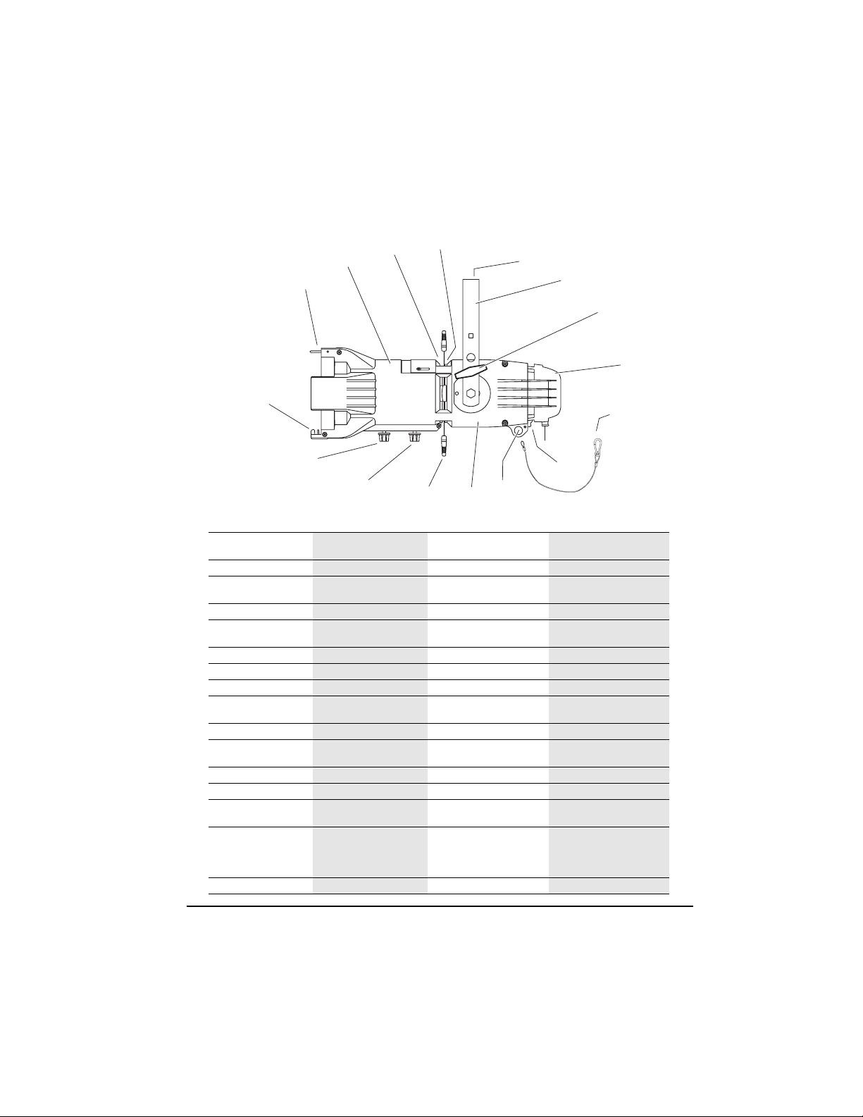
CE Source Four jr & CE Source Four jr Zoom
2
3
4
5
1
16
15
14
13
English Deutsch Français Español
Colour frame retaining
1
clip
2
Barrel
Drop-in iris slot cover Einschubfach für Irisblende Couverture du logement d’iris
3
4
Pattern holder slot
Primary suspension point
5
6
Yoke
7
Yoke locking knob
8
Lamp housing Lampengehäuse Compartiment lampe Portalámparas
Safety cable (ETC part
9
#7060A1022)
10
Earth continuity cable
Secondary suspension
11
point
12
Reflector housing
13
Shutters
Zoom rear focus knob
14
Beam focus knob
Zoom front focus knob
15
16
Colour frame holder
Sicherungsbügel des
Farbrahmens
Basisgehäuse Corps Tubo
Einschubfach für Globos Logement de porte-gobo Ranura del portagobos
Hauptbefestigungspunkt Point de suspension
Bügel Lyre Lira
Bügelfeststellschraube Poignée de serrage de la lyre Maneta para fijar la lira
Sicherungsseil
(ETC Teil #7060A1022)
Erdungskabel Câble de mise à la terre Cable de tierra
Zusatzbefestigungspunkt für
Sicherungsseil
Reflektorgehäuse Compartiment réflecteur Cubierta del reflector
Blenden Couteaux Cuchillas
Hinterer Zoomlinsen-
Fokussierknopf
Fokussierknopf
Vorderer ZoomlinsenFokussierknopf
Farbrahmenhalter Glissière du porte-filtre Marco portafiltros
Clip de maintien du portefiltre
amovible
principale
Câble de sécurité (pièce ETC
n°7060A1022)
Point de suspension
secondaire
Bouton de mise au point
arrière du Zoom
Bouton de réglage du
faisceau
Bouton de mise au point
avant du Zoom
12
11
6
7
8
9
10
Clip de seguridad del
portafiltros
Placa de la ranura para el iris
Punto primario de suspensión
Cable de seguridad (pieza
ETC #7060A1022)
Punto secundario de
suspensión
Maneta posterior de enfoque
del Zoom
Maneta para el enfoque del
haz
Maneta anterior de enfoque
del Zoom
CE Source Four jr & CE Source Four jr Zoom • 3
Page 6
18 19
PEAK
CENTER
FLAT
17
2120
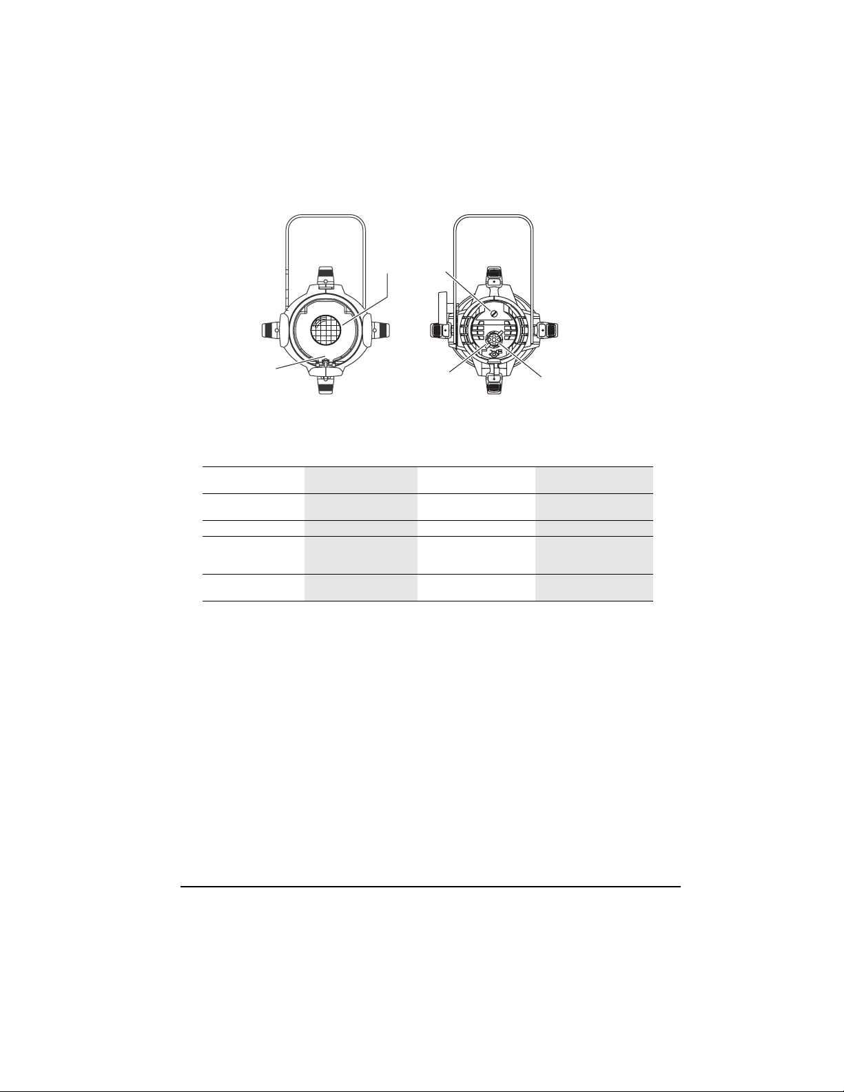
English Deutsch Français Español
Light baffle and retaining
17
screw
Lens tray with safety
18
screen
19
Knurled bolt
Peak and flat adjustment
20
(inner knob)
Centre adjustment (outer
21
knob)
Linsenhalterungsschiene
und Feststellschraube
Linsenrahmen mit
Schutzgitter
Piste de port de lentille et vis
de maintien
Tube lentille avec grille de
protection
Rändelschraube Boulon moleté Tornillo moleteado
Mitten- und
Flächenoptimierungseinstell
ung (innerer Knopf)
Réglage vertical et latéral
(bouton intérieur)
Zentrierung (äußerer Knopf) Réglage central (bouton
extérieur)
Carril para la lente y tornillo
de retención
Platillo del tubo con rejilla de
seguridad
Ajuste máximo y plano
(maneta externa)
Ajuste del centro (maneta
externa)
4 • CE Source Four jr & CE Source Four jr Zoom
Page 7
CE Source Four jr/Zoom instructions
0.6m
Safety warnings
The CE Source Four jr/Zoom high performance ellipsoidal spotlight is
intended for professional use only.
before using equipment.
before use.
• Do not mount the CE Source Four jr/Zoom on or near a flammable
surface.
• Use the luminaire in dry locations only, where humidity does not
exceed 90 percent. Luminaire is not intended for outdoor use.
• Mount and support the luminaire only by the primary suspension
yoke holes. Suspend the luminaire from a hook clamp or a stand
mount, using a securely tightened steel bolt (up to 12 mm Ø),
washer and locking nut.
• In addition to primary suspension, attach a safety cable (ETC part
#7060A1022) or chain to the secondary suspension point on the
luminaire (see page 3).
• Open all four shutters completely before turning the luminaire on.
• Always hang the CE Source Four jr/Zoom with the colour frame
retaining clip in the locked position.
• Always replace the lamp if it becomes damaged or thermally
deformed.
• Keep the luminaire at least 0.6 meters away from anything on
which it is shining. Lighted objects at this distance or greater will
not exceed 90ºC temperature from projected light.
• Disconnect the unit from power before all cleaning and
maintenance.
• Maximum ambient temperature: T
• Maximum exterior surface temperature: T
• A multilingual label sheet is included with this manual. Affix the label
of the appropriate language over the existing warning label on the
extension yoke. Do not cover the ETC trademark or CE mark.
Please note the following safety warnings
Read the entire user manual
=45°C
a
=235ºC
max
English
CE Source Four jr & CE Source Four jr Zoom • 5
Page 8
English
Wiring and power information
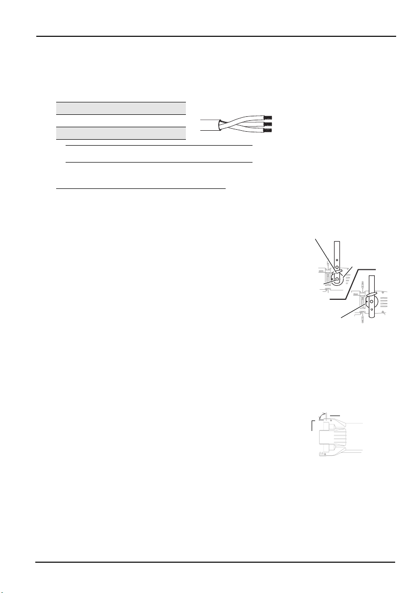
A plug of at least 2.5 amp (220/240V) rating should be attached to
the luminaire's mains lead. The wires in the mains lead are
1.5mm2 each and coloured in accordance with the following code:
Green and Yellow:
Blue: Neutral
Brown: Live
Earth
t 180°c
WARNING!
Current rating:
Operating frequency: 50/60Hz
This luminaire must be earthed.
120V/5 amp maximum
240V/2.5 amp maximum
Adjusting the yoke
To adjust the luminaire's position, loosen the yoke locking knob
and tilt the luminaire to the desired position. Retighten the yoke
locking knob to secure it.
CE Source Four jr/Zoom's two-position yoke allows you to modify
the overall height of the luminaire in the yoke.
1.
To change the yoke position, remove the yoke locking knob,
then remove the hex bolts on either side of the luminaire.
2.
Move the luminaire to the desired position (
3.
Replace and tighten the hex bolts and the locking knob.
Figure 1
Colour frame retaining clip
The colour frame holder is equipped with a spring-loaded
retaining clip that prevents colour frames and accessories from
falling out of the holder.
Important:
colour frame retaining clip in the locked position.
1.
Release the retaining clip by pushing it sideways. The r etaining
clip will pop open.
2.
Insert the colour frame.
3.
Press the retaining clip down until it locks into position.
Always hang CE Source Four jr/Zoom with the
Yoke locking
knob
Clutch disc
Hex bolt
Optional yoke
).
mounting position
Retaining clip
Locked
Figure 1
Unlocked
Figure 2
6 • CE Source Four jr & CE Source Four jr Zoom
Page 9
HPL lamps
HPL lamps are tungsten halogen lamps.
Important:
voltage at your facility. 230V and 240V HPL lamps are available.
Operating HPL lamps above their rated voltage reduces lamp life
and can cause premature lamp failure.
Verify that the HPL lamp you use is suitable for the
English
WARNING!
Do not use lamps other than the HPL in CE Source
Four jr/Zoom luminaires.
CE safety conformity and warranty.
Lamp code Watts Volts Color temp Ave rated life
HPL 575/230
HPL 575/240 575 240 3,200ºK 400 hour
Euro.
HPL 375/115 375 115 3,250ºK 300 hour
HPL 375/115X 375 115 3,050ºK 1,000 hour
HPL 550/77 550 77 3,250ºK 300 hour
HPL 550/77X 550 77 3,050ºK 2,000 hour
American
HPL 575/115 575 115 3,250ºK 300 hour
HPL 575/115X 575 115 3,050ºK 2,000 hour
HPL 575/120 575 120 3,250ºK 300 hour
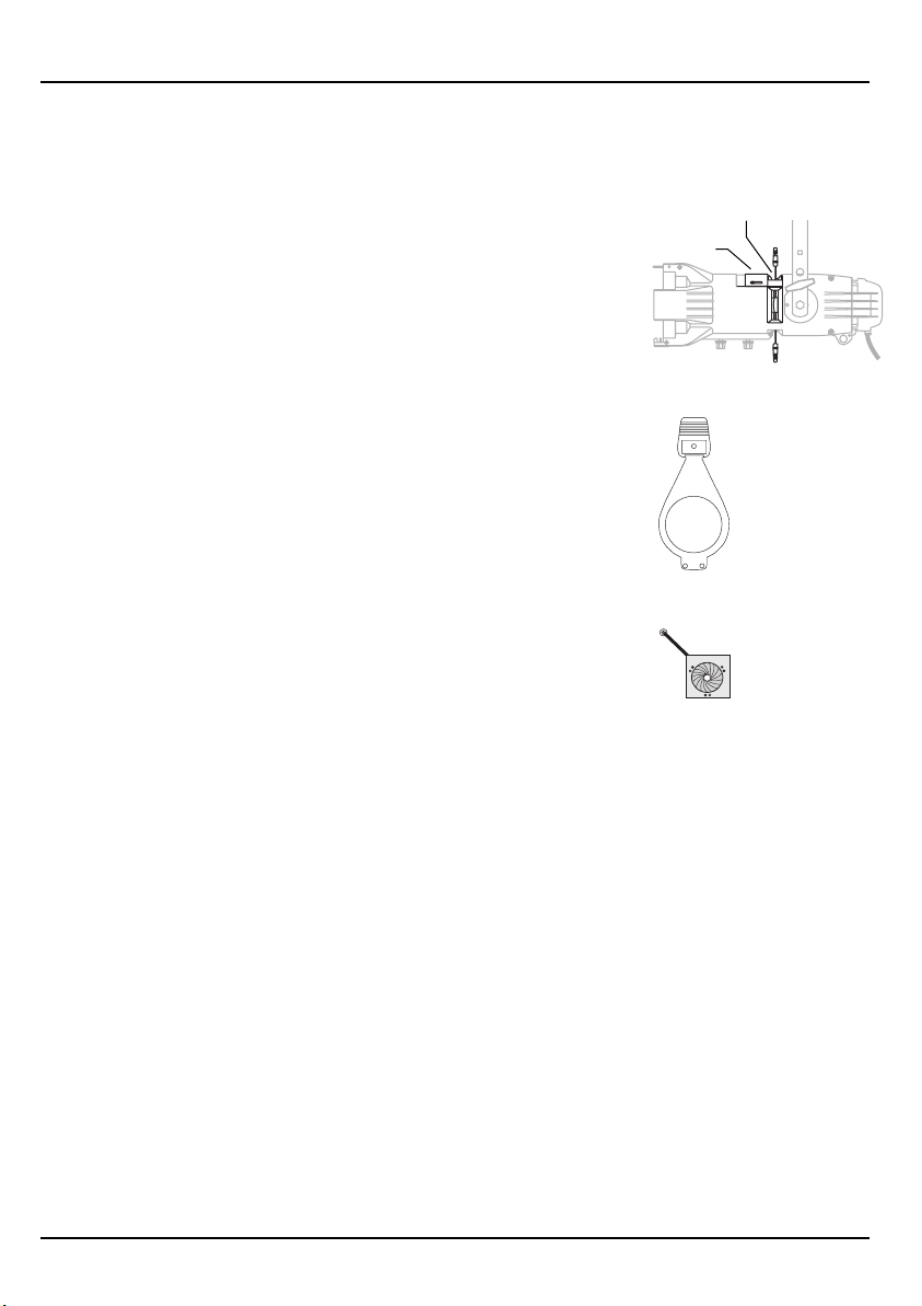
Installing the HPL lamp
Important:
luminaire.
Caution!
1.
Disconnect the unit from power before installing and replacing the
lamp.
WARNING!
The lamp must be installed before you use the
Always replace the lamp if it becomes damaged or
thermally deformed.
Let lamp cool before changing.
Use of lamps other than HPL will void
575 230 3,200ºK 400 hour
HPL lamp
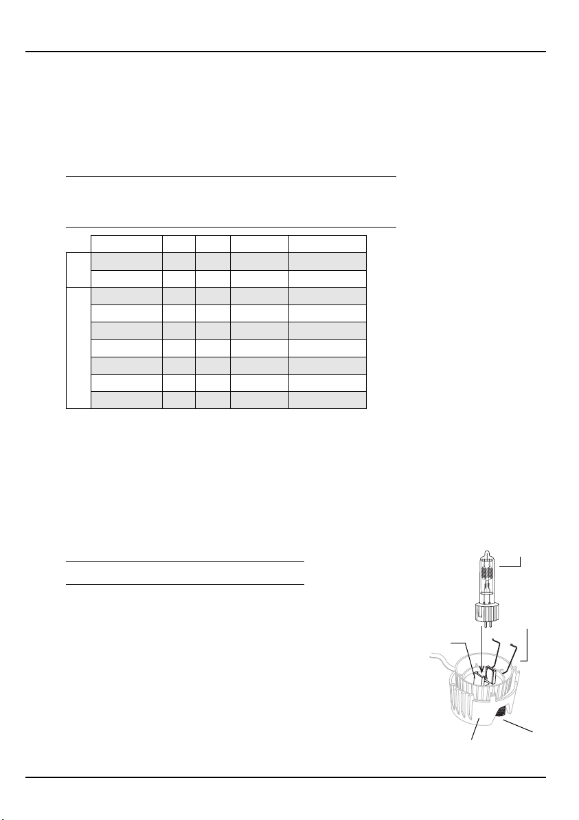
2.
Loosen the knurled bolt on the back of the lamp housing and pull
the housing straight out.
3.
Remove the HPL lamp from its box, holding it by the base.
Note:
To avoid premature lamp failure, do not touch the lamp glass.
If you do touch the lamp, clean it carefully with rubbing
alcohol and a clean, lint-free cloth before operation.
4.
Line up the flat sides of the lamp base with the retention brackets
on either side of the socket. See
5.
Push down on the lamp base until the lamp seats firmly. (The top of
the lamp base will be even with the top edges of the retention
brackets when it is properly installed.)
Figure 3
.
CE Source Four jr & CE Source Four jr Zoom • 7
Lamp
retention
brackets
Lamp
retainers
Knurled boltLamp housing
Figure 3
Page 10
English
Figure 4
Lamp housing Knurled bolt
Centre Peak and flat
adjustment
(outer knob)
adjustment
(inner knob)
Caution!
6.
Press lamp retainers down across lamp base and clip securely.
7.
To reinstall the lamp housing, line up the side fins and the bolt
hole, then tighten the knurled bolt to secure the housing.
Improperly installed lamps cause premature lamp
failure and socket problems.
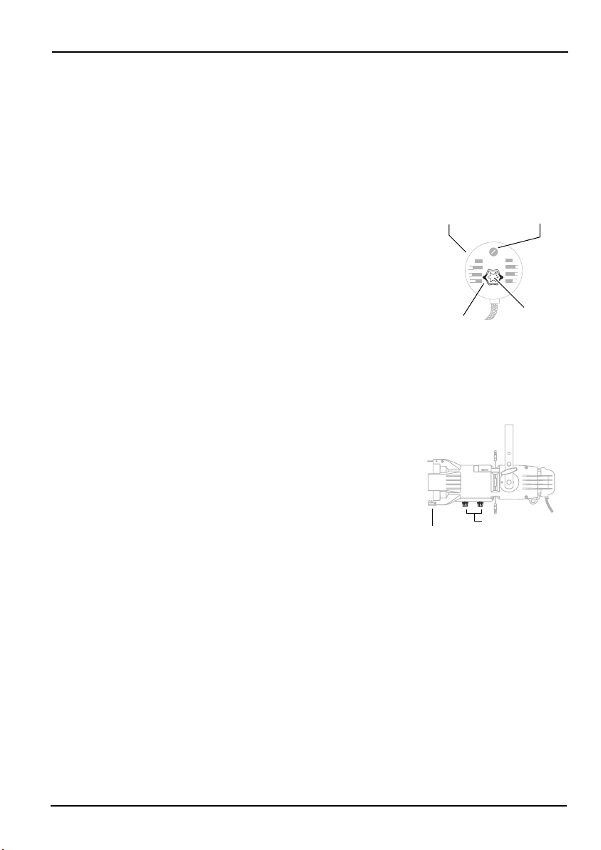
Aligning the lamp
Use the two concentric knobs on the rear of the lamp housing to
align the lamp. The outer knob centres the lamp within the
reflector and locks it in position; the inner knob fine tunes the
field. See
1.
2.
3.
4.
Figure 4
.
Important:
Unlock the outer knob by turning it anticlockwise one turn.
Gently push the outer knob from side to side and up and down
until the lamp is centred in the field.
Once the lamp is centred, tighten the outer knob to lock it in
place.
Turn the inner knob right or left to adjust for optimum flat field.
Luminaire must be on to align the lamp.
Focusing the beam
On a fixed field angle CE Source Four jr, with a 26°, 36° or 50°
lens, adjust the lens position to focus the edge of the beam. On a
CE Source Four jr Zoom, adjust the position of both lenses to set
the beam's spread and to focus the edge of the beam. The Zoom
lenses give you a range from 25° to 50°.
1.
Loosen the beam focus knob(s) on the underside of the barrel.
See
Figure 5
.
2.
Slide the lens(es) forward or backward to achieve the desired
beam edge.
3.
Once the luminaire is focused, tighten the beam focus
knob(s).
Colour frame
Beam focus knob
Figure 5
Gel notes
For best results, always use a high quality, high temperature
colour medium. ETC does not guarantee performance with low
temperature, saturated colour gels.
8 • CE Source Four jr & CE Source Four jr Zoom
Page 11
Shaping the beam
Figure 6
Drop-in
Pattern holder slot
iris slot
Figure 7
M-size pattern holder
(ETC part # 7062A1010)
Figure 8
Iris
(ETC part # 7062A1011)
You may shape the beam with the shutters, a pattern, or an optional
drop-in iris (ETC part #7062A1011).
Pattern projection
The pattern holder slot is on the top side of the barrel, immediately in
front of the shutters. It accommodates the M-size pattern holder
shown in
away from the shutter handle at a 30° angle. If your pattern holder’s
handle is straight, you may bend it far enough to not interfere with the
action of the shutter handle.
Use an optional donut (ETC part #7060A1037) in the accessory holder
to enhance pattern projection.
Drop-in iris slot
The drop-in iris slot is on the top side of the front barrel, immediately in
front of the pattern holder slot. See
small sheet metal cover secured with two crosshead screws prevents
light leakage and retains the iris assembly. To install an iris, follow
these steps.
1.
2.
3.
4.
Figure 7
Caution!
Use a crosshead screwdriver to loosen the screws on the drop-in
iris slot cover. Do not remove the screws.
Slide the cover completely forward, exposing the slot.
Insert the iris. The flat side must be toward the shutters and the iris
handle should extend out of slot.
Slide the slot cover back toward the shutters until it meets the iris
handle. Leave enough space to move the iris handle. Tighten the
screws.
. The M-size pattern holder’s handle should bend
Figure 6
. When it is not in use, a
Be certain the luminaire is not hot before installing the
iris.
English
CE Source Four jr & CE Source Four jr Zoom • 9
Page 12
English
Figure 9
Lens tray with
safety screen
Light baffle and
retaining screw
Switching lens assemblies
Follow these steps to replace a fixed field angle lens with Zoom
lenses.
1.
Loosen the screw at the front of the light baffle.
2.
Pull the light baffle out of the barrel.
3.
Remove the beam focus knob from the bottom of the barrel
and slide the lens assembly from the barrel.
4.
Slide the Zoom lens rear assembly into the barrel and install
its beam focus knob.
5.
Slide the Zoom lens front assembly into the barrel and install
its beam focus knob.
6.
Slide the light baffle back into place.
7.
Replace and tighten the screw at the front of the light baffle.
Note:
Reverse this procedure to replace Zoom lenses with a
standard lens.
Cleaning lenses
Caution!
1.
Remove the lens assembly. (See
above, steps 1-3.).
2.
Remove safety screen.
3.
Dampen a clean, lint-free cloth with vinegar or household
ammonia. You may also use water, but it will leave spots which
you may remove by polishing the lens gently with a clean, dry
cloth.
WARNING!
abrasive material to clean lenses. Glass and window
cleaners will stain the lens surface. Abrasive materials (such
as steel wool) will damage lenses.
4.
Starting from the centre, gently wipe the lens.
5.
Replace safety screen.
6.
Replace the lens assembly.
Change lenses if they become visibly damaged to
the extent that their effectiveness is impaired, for
example, by cracks or deep scratches.
Switching lens assemblies,
Never use glass and window cleaner or any
10 • CE Source Four jr & CE Source Four jr Zoom
Page 13

Accessories
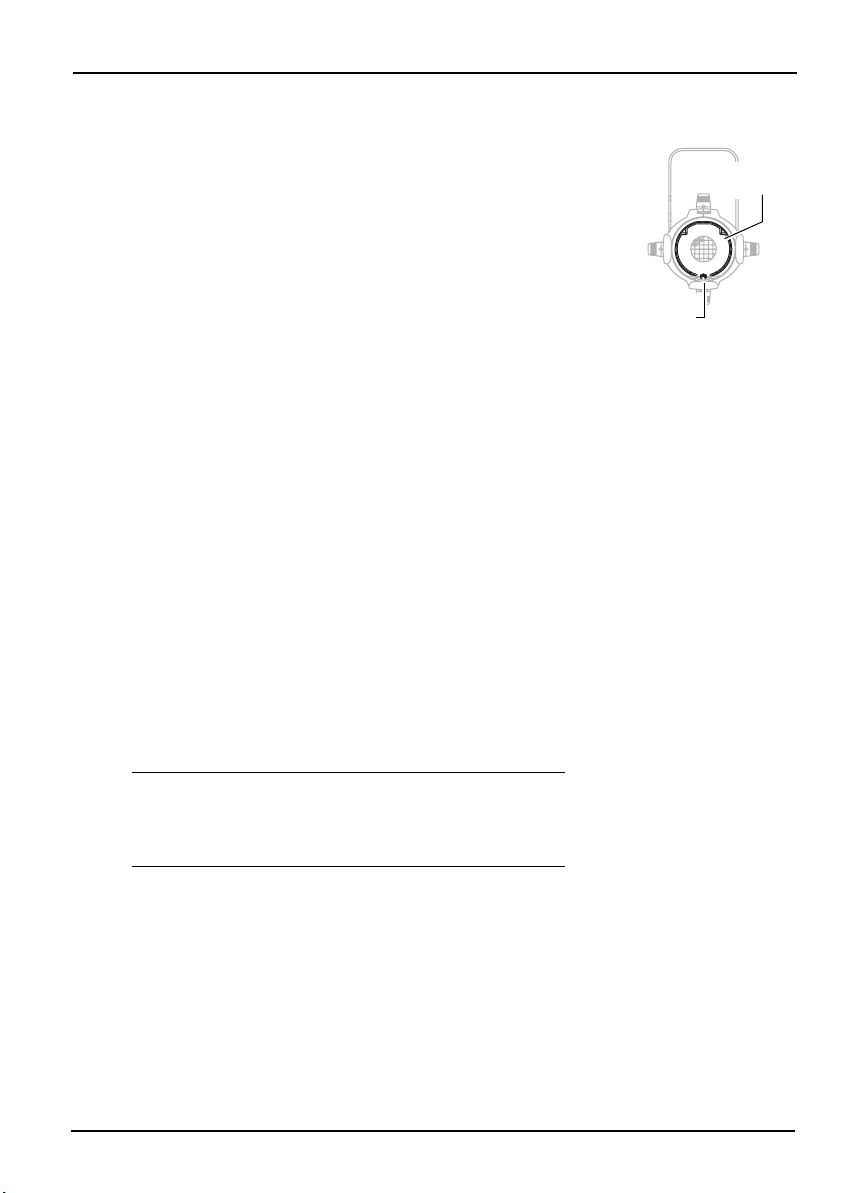
PAT point
Figure 10
Pattern holder, M-size 7062A1010
6.25” (15.875cm) donut 7060A1037
6.25" (15.875cm) top hat 7060A1018
6.25" (15.875cm) colour frame 7060A3043
Drop-in iris assembly 7062A1011
30" (76.2cm) safety cable, black 7060A1022
50º lens assembly 7062A2204
36º lens assembly 7062A2203
26º lens assembly 7062A2201
Zoom lens set 7062K4001
Zoom lens front assembly 7062A2005
Zoom lens rear assembly 7062A2006
Portable Appliance Test (PAT) Guidelines
What is PAT?
The Portable Appliance Test is a set of tests that must be administered
to electrical equipment in the UK and some locations in Europe to
ensure safety.
The tests are typically carried out using a small PAT device. The PAT
device connects to a power source and then attaches to the product
via an electrical outlet and test probes. The PAT provides a simple pass
or fail result, allowing rapid testing of large inventories.
The following guidelines provide instructions for applying the PAT to
the CE Source Four jr/Zoom.
English
Testing New Luminaires
CE Source Four jr/Zoom luminaires now include a specific PAT point
where the test clip is attached, as shown in the figure below. The PAT
test is comprised of two tests: the ground test and the insulation test.
Ground Test
The ground test indicates the safety of the ground connection to the
burner unit and reflector-housing parts. The connection could become
live if the insulation failed. It is not necessary to test continuity to
either the lens tube or the yoke, as these are separated by metallic
shields.
CE Source Four jr & CE Source Four jr Zoom • 11
Page 14

English
Follow the steps below to ground test a CE Source Four jr/Zoom
luminaire.
1.
Plug the luminaire into the PAT outlet and attach the test clip
to the PAT point on the luminaire.
2.
Set the PAT device to test at 10 amperes and press the GO/
TEST button.
If your PAT device doesn’t allow you to change the amperage, it
can still be used for the test. However, the earth tether, which
connects the burner assembly to the body of the unit, may get
hot enough to cause injury and could become permanently
discoloured. This is normal for test currents above approximately
20 amperes.
The PAT device should read less than 0.5 ohms. Most Source
Fours give a reading of less than 0.1 ohms, if in good condition.
The Insulation test
The insulation proves that the internal insulation is in good
condition. You can use standard PAT devices to perform the
insulation test. Follow the steps below to test the luminaire’s
insulation.
1.
Plug the luminaire into the PAT outlet and attach the test clip
to the PAT point on the luminaire.
2.
Set the PAT device to test at 500 volts D.C., then press the
G0/TEST button.
A reading below 1M ohms indicates a possible or imminent
failure. Moisture build-up around the lamp holder or in the
connector or foreign matter accumulated around electrical
connections can cause a low reading.
Why a CE Source Four jr/Zoom may give a fail reading
The majority of appliances must fulfill a ground resistance
requirement of 0.1 ohms or less. Some simple, low-cost PAT
devices assume the 0.1 requirement and do not offer a method
for reading the actual resistance or for setting the fail level to 0.5
ohms. These devices may provide a fail reading for an acceptable
unit if the resistance is slightly above 0.1 ohms. If in doubt, check
with your PAT device supplier and verify that the PAT device can
correctly test a luminaire for the 0.5 ohm condition.
How often to test
Your local regulatory authority has guidelines on the testing
frequency.
12 • CE Source Four jr & CE Source Four jr Zoom
Page 15

CE Source Four jr Bedienungsanleitung
0.6m
Sicherheitshinweise
• Der CE Source Four jr ist ein Ellipsenscheinwerfer mit hoher
Leistung, der nur durch Fachpersonal bedient werden sollte.
lesen Sie vor dem Einsatz die Gebrauchsanleitung
vor Gebrauch die folgenden Sicherheitshinweise:
• Befestigen Sie den CE Source Four jr nicht an oder in der Nähe von
entzündbaren Oberflächen.
• Den Scheinwerfer nur in trockenen Räumen einsetzen, wo die
Luftfeuchtigkeit unter 90% liegt. Der Scheinwerfer ist nicht für den
Außeneinsatz geeignet.
• Den Scheinwerfer nur mit Hilfe der Hauptaufhängelöcher des
Bügels montieren und sichern. Den Scheinwerfer an einer
Hakenklemme oder an einem Stativ mit einer festgedrehten
Stahlschraube (bis zu 12 mm Durchmesser), U-Scheibe und
Sperrmutter befestigen.
• Stellen Sie sicher, daß am Scheinwerfer neben der
Hauptbefestigung auch ein Sicherheitsseil (ETC Teil #7060A1022) an
der Befestigungsmöglichkeit für das Sicherungsseil angebracht ist.
(see page 3)
• Die vier Blenden müssen vor dem Einschalten des Scheinwerfers
vollständig geöffnet sein.
• Der Sicherungsbügel des Farbrahmens muß beim Aufhängen des
CE Source Four jr immer in Verschlußposition sein.
• Lampen die beschädigt oder durch Hitzeeinwirkung verformt sind,
müssen umgehend ersetzt werden.
• Der Scheinwerfer sollte mindestens 0,6 m von angestrahlten
Gegenständen entfernt sein. Bei Einhaltung dieses oder eines
größeren Abstandes, erwärmen sich die angestrahlten
Gegenstände durch den Lichtstrahl bis max. 90 °C.
• Der Scheinwerfer muß vor dem Reinigen oder vor Wartungsarbeiten
allpolig vom Netz getrennt werden.
• Maximale Raumtemperatur: T
• Maximale Temperatur der Außenoberflächen: T
• Dieser Anleitung liegt ein Blatt mit Etiketten in verschiedenen
Sprachen bei. Kleben Sie das Etikett der entsprechenden Sprache
über den angebrachten Warnungsaufkleber am Haltebügel. Die ETC
Marke und die CE Marke nicht überkleben.
=45 °C
a
max
=235 °C
Bitte
. Beachten Sie
Deutsch
CE Source Four jr & CE Source Four jr Zoom • 13
Page 16

Deutsch
Hinweise für den Anschluß ans Netz
Für den Netzanschluß des Scheinwerfers sollte ein Stecker mit
einer Mindestbelastbarkeit von 2,5A (220/240V) verwendet
werden. Die Drähte im Netzanschlußkabel haben einen
Durchmesser von 1,5 mm und sind entsprechend den folgenden
Farben kodiert:
Grün und gelb:
Blau: Nulleiter
Braun: Stromführend
Schutzleiter
t 180°c
ACHTUNG!
Stromversorgung:
Betriebsfrequenz: 50/60Hz
Dieser Scheinwerfer muß geerdet werden.
maximal 120V/5A
maximal 240V/2,5A
Einstellen des Bügels
Zum Einstellen der Position des Scheinwerfers die
Bügelfeststellschraube lockern und dann den Scheinwerfer in die
gewünschte Position neigen. Bügelfeststellschraube erneut
anziehen um ihn festzuhalten.
Source Four jr’s 2-Positionen Bügel erlaubt die Einstellung der
Höhe des Scheinwerfers innerhalb des Bügels.
1.
Zum Ändern der Bügelposition zuerst die Bügelfeststellschraube entfernen, dann die Sechskantschrauben auf
beiden Seiten des Scheinwerfers herausnehmen.
2.
Den Scheinwerfer in die gewünschte Position setzen. Siehe
Abbidung 1
3.
Die Sechskantschrauben und die Bügelfeststellschraube
wieder einsetzen und festziehen.
.
Sicherungsbügel des Farbrahmens
Der Farbrahmenhalter ist mit einem gefederten Sicherungsbügel
ausgestattet, der verhindert, daß Farbrahmen und Zubehör aus
dem Rahmen herausfallen können.
Wichtig:
Sicherungsbügel in geschlossener Position aufgehängt
werden.
1.
Den Sicherungsbügel öffnen. Wenn er seitlich gedrückt wird,
springt er auf.
2.
Den Farbrahmen hineinstecken.
3.
Den Sicherungsbügel nach unten drücken, bis er einrastet.
Der CE Source Four jr sollte immer mit dem
Bügelfeststellschraube
Unterlegescheibe
Sechskantschraube
Optionale
Bügelbefestigungposition
Abbidung 1
Sicherungsbügel
Ungesichert
Gesichert
Abbidung 2
14 • CE Source Four jr & CE Source Four jr Zoom
Page 17

HPL Lampen
HPL lampe
Abbidung 3
Lampenhalter
Rändelschraube
Lampengehäuse
Lampenhalterklammern
HPL Lampen sind Tungstenhalogenlampen
Wichtig:
verwenden, für die Spannung in Ihrem Gebäude geeignet ist. Es
sind 230V und 240V HPL Lampen lieferbar. Die Verwendung von
HPL Lampen mit Spannungen die über ihrem Richtwert liegen,
verkürzt die Lebensdauer der Lampe und kann zu frühzeitigem
Versagen der Lampe führen.
Vergewissern Sie sich, daß die HPL Lampe die Sie
Deutsch
ACHTUNG!
Lampen verwenden.
Für den CE Source Four jr Scheinwerfer nur HPL
Wenn keine HPL-Lampen eingesetzt
werden, entspricht der Scheinwerfer nicht mehr den CE
Sicherheitsnormen und es erlischt die Garantie.
Lampencode Watt Volt Farbtemperatur Mittiere Lebensdauer
HPL 575/230
HPL 575/240 575 240 3,200ºK 400 Stunden
Euro.
HPL 375/115 375 115 3,250ºK 300 Stunden
HPL 375/115X 375 115 3,050ºK 1,000 Stunden
HPL 550/77 550 77 3,250ºK 300 Stunden
HPL 550/77X 550 77 3,050ºK 2,000 Stunden
HPL 575/115 575 115 3,250ºK 300 Stunden
Amerikanische
HPL 575/115X 575 115 3,050ºK 2,000 Stunden
HPL 575/120 575 120 3,250ºK 300 Stunden
575 230 3,200ºK 400 Stunden
Einbau der HPL Lampe
Wichtig:
installiert werden.
Vorsicht!
1.
Der Scheinwerfer muß vor Einbau und Austausch der Lampe vom
Netz getrennt werden.
ACHTUNG!
Die Lampe muß vor Inbetriebnahme des Scheinwerfers
Lampen, die beschädigt oder durch Hitzeeinwirkung
verformt sind, müssen umgehend ersetzt werden.
Die Lampe vor dem Auswechseln abkühlen lassen.
2.
3.
Die Rändelschraube an der Rückseite des Lampengehäuses
lockern, und das Gehäuse nach hinten abziehen.
Die HPL Lampe am Sockel festhalten und aus der Verpackung
nehmen.
Hinweis:
Um frühzeitiges Versagen der Lampe zu vermeiden, sollte
das Glas der Lampe nicht berührt werden. Sollte es doch zu
einer Berührung des Glases kommen, muß die Lampe vor
Inbetriebnahme vorsichtig mit Spiritus und einem
fusselfreien Tuch saubergemacht werden.
CE Source Four jr & CE Source Four jr Zoom • 15
Page 18

Deutsch
Abbidung 4
Lampengehäuse
Rändelschraube
Mitten- und
Flächenoptimierungseinstellung (innerer Knopf
Zentrierung
(äußerer Knopf)
4.
Richten Sie die flachen Seiten des Lampensockels an den
beiden Lampensockelhaltern aus. Siehe
5.
Am Lampensockel nach unten drücken, bis die Lampe gut
sitzt. (Wenn die Lampe richtig installiert ist, ist die Oberkante
des Lampensockels bündig mit der Oberkante der Fassung).
Vorsicht!
6.
Die Lampenhalterklammern über den Sockel legen und
sichern.
7.
Das Lampengehäuse zum Wiedereinbau an den Seitenfinnen
und am Loch für die Schraube ausrichten, und dann die
Rändelschraube festdrehen bis das Gehäuse sicher sitzt.
Falsch installierte Lampen führen zu frühzeitigem
Versagen der Lampe und zu Problemen mit dem
Sockel.
Abbidung 3
Einstellen der Lampe
Die zwei konzentrischen Knöpfe an der Rückwand des
Lampengehäuses dienen dem Einstellen der Lampe. Der äußere
Knopf zentriert die Lampe innerhalb des Reflektors und verriegelt
sie. Mit dem inneren Knopf wird das Feld feinabgestimmt. Siehe
Abbidung 4
Wichtig:
1.
Entriegeln Sie den äußeren Knopf, indem Sie ihn eine Drehung gegen den Uhrzeigersinn drehen.
2.
Den äußeren Knopf so verschieben, daß die Lampe im Feld
zentriert ist.
3.
Wenn die Lampe zentriert ist, den äußeren Knopf festdrehen,
um die Lampe zu verriegeln.
4.
Zur optimalen Flächeneinstellung den inneren Knopf nach
rechts und links drehen.
.
Die Lampe muß zum Einstellen eingeschaltet sein.
.
Fokussierung des Lichtstrahls
16 • CE Source Four jr & CE Source Four jr Zoom
An einem CE Source Four jr mit festem Feldwinkel und einer 26°,
36° oder 50° Linse, wird die Schärfe durch justieren der Position
der Linse eingestellt. An einem CE Source Four jr Zoom, werden
die Positionen beider Linsen justiert um Streuwinkel und Schärfe
des Lichtstrahls einzustellen. Die Zoomlinsen bieten einen
Bereich von 25° bis 50°.
1.
Den Fokussierknopf (bzw. die Fokussierknöpfe) an der
Unterseite des Basisgehäuses lösen. Siehe
2.
Die Linse(n) vorwärts oder rückwärts schieben bis die
gewünschte Schärfeeinstellung erreicht ist.
3.
Wenn der Scheinwerfer fokussiert ist, den Fokussierknopf
(bzw. die Fokussierknöpfe) festdrehen.
Abbidung 5
.
Farbrahmen
Fokussierknöpfe
Abbidung 5
Page 19

Hinweise für Farbfilter
Abbidung 6
Einschubfach für Gobohalter
Einschubfach
für Irisblende
Abbidung 7
Gobohalter der Größe M
(ETC Teil # 7062A1010)
Abbidung 8
Irisblende
(ETC Teil # 7062A1011)
Für beste Ergebnisse, empfehlen wir, nur hitzebeständige
Qualitätsfarbfilter zu verwenden. Bei Verwendung von kräftigen
Farbfiltern, die nicht hitzebeständig sind, übernimmt ETC keine
Garantie für die Leistung.
Lichtstrahlbegrenzung
Der Strahl kann mit Blendeschiebern, einem Gobo, oder einer
(optionalen) einschiebbaren Irisblende (ETC Teil #7062A1011) geformt
werden.
Projektion von Gobos
Das Einschubfach für Gobohalter befindet sich an der Oberseite des
Basisgehäuses, direkt vor den Blenden. In das Einschubfach paßt der
in
Abbidung 7
Der Griff des Gobohalters der Größe M sollte vom Blendengriff um 30°
abgewinkelt sein. Falls der Gobohaltergriff gerade ist, kann er weit
genug abgebogen werden um nicht bei der Bewegung des
Blendengriffes zu stören.
Es besteht die Möglichkeit durch Verwendung einer Lochblende (Teil
#7060A1037) im Zubehörhalter die Projektion von Gobos zu
verbessern.
dargestellte Gobohalter der Größe M.
Deutsch
Einschubfach für Irisblende
Das Einschubfach für die Irisblende befindet sich an der Oberseite des
vorderen Basisgehäuses, direkt vor dem Einschubfach für Gobohalter.
Siehe
es mit einem kleinen Blechdeckel und zwei Kreuzschlitzschrauben
abgedeckt werden, so daß kein Licht austritt und den
Irisblendenrahmen festhält. Eine Irisblende wird folgendermaßen
installiert:
Vorsicht!
1.
Mit einem Kreuzschlitzschraubenzieher die Schrauben des Deckels
des Einschubfaches für die Irisblende lösen. Die Schrauben nicht
ganz herausdrehen.
2.
Den Deckel ganz nach vorne schieben und damit die Öffnung
freilegen.
3.
Die Irisblende einstecken. Die flache Seite muß auf die Blenden
zeigen, und der Griff der Irisblende sollte aus dem Einschubfach
herausragen.
4.
Den Deckel in Richtung der Blenden schieben, bis er den Griff der
Irisblende berührt.Genügend Raum lassen, so daß der Griff der
Irisblende bewegt werden kann. Danach die Schrauben festdrehen.
Abbidung 6
Stellen Sie sicher daß der Scheinwerfer nicht heiß ist,
bevor Sie die Irisblende installieren.
. Wenn das Einschubfach nicht benötigt wird, kann
CE Source Four jr & CE Source Four jr Zoom • 17
Page 20

Deutsch
Abbidung 9
Linsenrahmen
mit Schutzgitter
Linsenhalterungsschiene
und Sicherungsschraube
Linsenhalter austauschen
Befolgen Sie diese Schritte um eine Linse mit festem Feldwinkel
durch Zoomlinsen zu ersetzen.
1.
Feststellschraube am vorderen Ende der Linsenhalterungsschiene lösen.
2.
Linsenhalterungsschiene aus dem Basisgehäuse
herausziehen.
3.
Den Fokussierknopf von der Untersiete des Basisgehäuses
entfernen und Linsenhalterung aus dem Gehäuse
herausziehen.
4.
Hintere Zoomlinsenhalterung in das Gehause hineinschieben
und dessen Fokussierknopf installieren.
5.
Vordere Zoomlinsenhalterung in das Gehäuse hineinschieben
und dessen Fokussierknopf installieren.
6.
Linsenhalterungsschiene wieder einsetzen.
7.
Schraube am vorderen Ende der Linsenhalterungsschiene
wieder einsetzen und festdrehen.
Hinweis:
Diesen Ablauf in umgekehrter Reihenfolge
durchführen, wenn Zoomlinsen mit Standardlinsen
ersetzt werden.
Säuberung der Linsen
Vorsicht!
1.
2.
3.
4.
5.
6.
18 • CE Source Four jr & CE Source Four jr Zoom
Linsen die sichtbare Schäden haben, wie zum
Beispiel Risse oder tiefe Kratzer, und deren
Leistungsfähigkeit dadurch eingeschränkt ist,
müssen ausgetauscht werden.
Linsenhalter entfernen. (Siehe oben
chen
, Schritte 1-3.)
Das Schutzgittter entfernen.
Ein sauberes, fusselfries Reinigungstuch mit Essig oder
Haushaltsammoniak anfeuchten. Es kann auch Wasser
verwendet werden, allerdings hinterläßt dies Flecken die
anschließend durch sanftes Polieren der Linse mit einem
sauberen, trockenem Tuch entfernt werden können.
ACHTUNG!
Fensterreinigungsmittel oder mit scheuernden Mitteln gereinigt
werden. Glas- und Fensterreinigungsmittel hinterlassen Flecken
auf der Linsenoberfläche. Scheuernde Mittel (wie zum Beispiel
Stahlwolle) beschädigen die Linse.
WVon der Mitte ausgehend, die Linse sanft reinigen.
Das Schutzgitter wieder einsetzen.
Linsenhalter wieder einsetzen.
Die Linsen dürfen nie mit Glas- und
Linsenhalter austaus-
Page 21

Zubehör
Gobohalter, Größe M 7062A1010
6,25” (15,875cm) Locheblende 7060A1037
6,25” (15,875cm) Tubet 7060A1018
6,25” (15,875cm) Farbrahmen 7060A3043
Rahmen für Einschubblende 7062A1011
30” (76,2cm) Sicherungsseil, schwarz 7060A1022
50° Linsenhalter 7062A2204
36° Linsenhalter 7062A2203
26° Linsenhalter 7062A2201
Zoom Linsen Set 7062K4001
Vordere Zoomlinsenhalterung 7062A2005
Hintere Zoomlinsenhalterung 7062A2006
Deutsch
CE Source Four jr & CE Source Four jr Zoom • 19
Page 22

Deutsch
20 • CE Source Four jr & CE Source Four jr Zoom
Page 23

Mode d’emploi CE Source Four jr
0.6m
Avertissements de sécurité
Le projecteur à faisceau concentré ellipsoïdal à haute performance CE
Source Four jr est uniquement destiné à un usage professionnel.
la notice d’utilisation en entier avant d’utiliser cet équipement.
Prendre connaissance des avertissements de sécurité suivants avant
d’employer cet équipement.
• Ne pas installer le CE Source Four jr sur ou à côté d’une surface
inflammable.
• Employer le luminaire seulement dans des endroits secs, où
l’humidité ne dépasse pas 90 pour cent. Le luminaire n’est pas
conçu pour être utilisé à l’extérieur.
• Installer et supporter le luminaire seulement par les trous de la lyre
de suspension principale. Suspendre le luminaire à un crochet ou à
un support, en utilisant un boulon d’acier (jusqu’à 12 mm Ø), une
rondelle et un contre-écrou bien serrés.
• Outre la suspension principale, attacher un câble de sécurité (pièce
ETC n° 7060A1022) ou une chaîne au point de suspension
secondaire du luminaire (voir la page 3).
• Ouvrir complètement les quatre couteaux avant d’allumer le
luminaire.
• Toujours s’assurer que le clip de maintien du porte-filtre est bien
verrouillé avant d’accrocher le CE Source Four jr.
• Toujours remplacer une lampe endommagée ou déformée sous
l’effet de la chaleur.
• Garder le luminaire à 0,6 mètre au moins de l’objet sur lequel il est
pointé. La température des objets illuminés placés à cette distance
ou plus loin ne dépassera pas 90°C due à la lumière projetée.
• Débrancher l’unité avant tout nettoyage ou entretien.
• Température ambiante maximum: Ta = 45°C
Français
Lire
• Température maximum de la surface extérieure: T
• Une feuille d’étiquettes de sécurité en plusieurs langues est jointe à
ce manuel. Coller l’étiquette dans la langue appropriée par-dessus
celle qui se trouve sur la lyre de rallonge. Ne pas couvrir la marque
déposée ETC ni la marque CE.
= 235°C
max
CE Source Four jr & CE Source Four jr Zoom • 21
Page 24

Français
Câblage électrique
Monter une fiche d’au moins 2,5A (220/240V) au câble
d’alimentation du luminaire. Les fils du câble d’alimentation font
chacun 1,5 mm2 et sont colorés selon le code suivant:
Vert et jaune:
Bleu: Neutre
Marron: Sous tension
Te rr e
t 180°c
ATTENTION!
Puissance électrique:
Fréquence de service 50/60Hz
Ce luminaire doit être mis à la terre.
120V/5A maximum
240V/2,5A maximum
Réglage de la lyre
Afin de régler la position du luminaire, desserrer la poignée de
serrage de la lyre et incliner le luminaire en position voulue.
Resserrer la poignée de serrage de la lyre pour le fixer en place.
La lyre à deux positions du Source Four jr permet modifier la
hauteur d’ensemble du luminaire dans la lyre.
1.
Afin de modifier la position de la lyre, enlever la poignée de
serrage de la lyre, ensuite enlever les boulons d’attachement
des deux côtés de la lyre.
2.
Disposer le luminaire en position voulue (
3.
Remettre et resserrer les boulons d’attachement et la poignée
de serrage.
Figure 1
Clip de maintien du porte-filtre
La glissière porte-filtre est munie d’un clip de maintien à ressort
qui empêche que les porte-filtres et les accessoires ne tombent
de la glissière porte-filtre.
Attention:
filtre est bien verrouillé avant d’accrocher le CE Source Four jr.
1.
Dégager le clip de maintien en appuyant dessus latéralement
jusqu’à ce que le clip s’ouvre.
2.
Insérer le porte-filtre.
3.
Appuyer sur le clip de maintien jusqu’à ce qu’il soit fixé en
position.
Toujours s’assurer que le clip de maintien du porte-
Poignée de
serrage de la lyre
Disque
de prise
Boulon
d’attachement
).
Position alternative
d’attachement de lyre
Position
verrouillée
Figure 1
Clip de maintien
Position
non-verrouillée
Figure 2
22 • CE Source Four jr & CE Source Four jr Zoom
Page 25

Lampes HPL
Les lampes HPL sont des lampes halogènes tungstène.
Attention:
compatible avec le voltage de vos installations. Des lampes HPL de
230V et 240V sont disponibles. L’utilisation d’une lampe HPL audessus de son voltage nominal réduit sa durée de vie et peut
provoquer un arrêt de fonctionnement prématuré.
Vérifiez que la lampe HPL que vous utilisez est
Français
ATTENTION!
N’utilisez que des lampes HPL dans les luminaires
CE Source Four jr. L’utilisation de toute autre lampe qu’une lampe
HPL annule la conformité et la garantie de sécurité CE.
Code de lampe Watts Volts Temp.
HPL 575/230
HPL 575/240 575 240 3,200ºK 400 heures
euro.
HPL 375/115 375 11 5 3,250ºK 300 heures
HPL 375/115X 375 115 3,050ºK 1,000 heures
HPL 550/77 550 77 3,250ºK 300 heures
HPL 550/77X 550 77 3,050ºK 2,000 heures
HPL 575/115 575 11 5 3,250ºK 300 heures
américaines
HPL 575/115X 575 115 3,050ºK 2,000 heures
HPL 575/120 575 120 3,250ºK 300 heures
575 230 3,200ºK 400 heures
couleur
Durée de vie moy.
Installation de la lampe HPL
Attention:
Attention!
1.
Débrancher l’appareil avant d’installer et de remplacer la lampe.
ATTENTION!
2.
Desserrer le boulon moleté au dos du compartiment lampe et
retirer le compartiment du luminaire.
3.
Sortir la lampe HPL de sa boîte, en la tenant par le culot.
NB:
4.
Aligner les côtés plats du culot de la lampe et les attaches placées
de part et d’autre de la douille.
5.
Enfoncer le culot jusqu’à ce que la lampe soit bien en place.
(Lorsqu’elle est bien montée, le haut du culot de la lampe doit
arriver au même niveau que le haut des attaches.)
Installez la lampe avant d’utiliser le luminaire.
Toujours remplacer une lampe endommagée ou
déformée sous l’effet de la chaleur.
Laisser refroidir la lampe avant de la changer.
Pour éviter une panne prématurée de la lampe, ne pas
toucher la partie en verre. Si vous touchez à la partie en
verre, nettoyez-la soigneusement avec de l’alcool à 90° et un
chiffon non pelucheux avant d’utiliser la lampe.
Attaches
de la lampe
Compartiment
lampe
Lampe HPL
Dispositif de
retenue de
la lampe
Boulon moleté
Figure 3
CE Source Four jr & CE Source Four jr Zoom • 23
Page 26

Français
Figure 4
Boulon moleté
Compartiment
lampe
Réglage vertical et
latéral (bouton intérieur)
Réglage central
(bouton extérieur)
Attention!
6.
Abaisser le dispositif de retenue sur le culot de la lampe et
l’attacher solidement.
7.
Pour installer le compartiment lampe, aligner les ailettes
latérales et le trou du boulon, ensuite serrer le boulon moleté
pour fixer le compartiment.
Une lampe mal installée risque de tomber en
panne prématurément et d’endommager la
douille.
Alignement de la lampe
Pour aligner la lampe, utiliser les deux boutons concentriques
situés au dos du compartiment lampe. Le bouton extérieur centre
la lampe dans le réflecteur et la maintient en position; le bouton
intérieur règle le champ avec plus de précision.
Attention:
la lampe.
1.
Déverrouiller le bouton extérieur en le faisant tourner dans le
sens inverse des aiguilles d’une montre.
2.
Faire jouer doucement le bouton de droite à gauche et de haut
en bas jusqu’à ce que la lampe soit centrée dans le champ.
3.
Une fois que la lampe est centrée, serrer le bouton extérieur
pour l’immobiliser.
4.
Tourner le bouton intérieur vers la droite ou vers la gauche
pour obtenir un champ plan optimum.
Le luminaire doit être branché pour pouvoir aligner
Mise au point du faisceau lumineux
24 • CE Source Four jr & CE Source Four jr Zoom
Sur un CE Source Four jr à angle de champ fixe, avec une lentille
de 26˚, 36˚ ou 50˚, régler la position de la lentille pour mettre au
point le contour du faisceau. Sur un CE Source Four jr Zoom,
régler la position des deux lentilles pour déterminer l’angle de
faisceau et mettre au point le contour du faisceau. Les lentilles du
Zoom donnent une gamme de 25˚ à 50˚.
1.
Desserrer le(s) bouton(s) de réglage du faisceau situé(s) sur la
partie inférieure du corps. Voir la
2.
Faire glisser le(s) lentille(s) vers l’avant ou vers l’arrière pour
obtenir le contour de faisceau désiré.
3.
Une fois que la mise au point du luminaire est effectuée,
serrer le(s) bouton(s) de réglage du faisceau.
Figure 5
.
Porte-filtre
Boutons de
réglage du faisceau
Figure 5
Page 27

La gélatine
Figure 6
Logement de porte-gobo
Logement
d’iris amovible
Figure 7
Porte-gobo taille M
(pièce ETC n°7062A1010)
Figure 8
Iris
(pièce ETC n° 7062A1011)
Pour les meilleurs résultats, toujours utiliser un véhicule couleur haute
température d’excellente qualité. ETC ne peut pas garantir de bonnes
performances avec des gélatines de couleur intense et de basse
température.
Mise en forme du faisceau lumineux
Vous pouvez donner une forme à votre faisceau lumineux en utilisant
les couteaux, un gobo, ou un iris amovible optionnel (pièce ETC n°
7062A1011).
Projection de formes
Le logement de porte-gobo se trouve sur la partie supérieure du corps,
juste devant les couteaux. Il permet l’emploi du porte-gobo taille M.
Figure 8
Voir la
30° dans la direction opposée à la poignée des couteaux. Si la poignée
de votre porte-gobo est droite, vous pouvez la courber jusqu’à ce
qu’elle ne bloque pas le mouvement de la poignée de couteaux.
Utiliser un donut optionnel (pièce ETC n° 7060A1037) dans le porteaccessoires pour améliorer la projection de formes.
Logement d’iris amovible
Le logement d’iris amovible se trouve sur la partie supérieure du corps
avant, juste devant le logement de porte-gobo. Voir la
Lorsqu’il n’est pas utilisé, un petit volet métallique fixé par deux vis
cruciformes empêche les pertes de lumière et maintient en place le
montage de l’iris. Pour installer l’iris, suivre les directives suivantes.
Attention!
1.
A l’aide d’un tournevis cruciforme, desserrer les vis du volet du
logement d’iris. Ne pas enlever les vis.
2.
Découvrir le logement en faisant glisser le volet complètement vers
l’avant.
3.
Insérer l’iris. La surface plate doit être tournée vers les couteaux et
le manche de l’iris doit dépasser du logement.
4.
Refermer le volet en le faisant glisser vers les couteaux jusqu’au
manche de l’iris. Laisser suffisamment de place pour bouger le
manche de l’iris. Serrer les vis.
. La poignée du porte-gobo taille M devrait inclinée de
Figure 6
Assurez-vous que le luminaire n’est plus chaud avant
d’installer l’iris.
Français
.
CE Source Four jr & CE Source Four jr Zoom • 25
Page 28

Français
Figure 9
Piste de port de
lentille et vis de maintien
Tube lentille avec
grille de protection
Changement des montages de lentille
Suivre les instructions ci-dessous pour remplacer une lentille à
angle de champ fixe par des lentilles Zoom.
1.
Desserrer les vis à l’avant de la piste de port de lentille.
2.
Sortir la piste de port de lentille du corps.
3.
Enlever le bouton de réglage du faisceau de la partie inférieure
du corps et retirer le montage de lentille du corps.
4.
Introduire le montage arrière de lentille Zoom dans le corps et
mettre en place son bouton de réglage de faisceau.
5.
Introduire le montage avant de lentille Zoom dans le corps et
mettre en place son bouton de réglage de faisceau.
6.
Remettre la piste de port de lentille à sa place.
7.
Remettre et serrer les vis à l’avant de la piste de port de
lentille.
NB:
Effectuer l’opération inverse pour remplacer des
lentilles Zoom par des lentilles normales.
Nettoyage des lentilles
Attention!
1.
Enlever le montage de lentille. (Voir
montages de lentille
2.
Enlever la grille de protection.
3.
Humecter un chiffon non pelucheux avec du vinaigre ou de
l’ammoniaque. Vous pouvez aussi utiliser de l’eau, mais cela
laissera des taches que vous pourrez enlever en frottant
légèrement la lentille avec un chiffon propre et sec.
ATTENTION!
vitres ou de matériau abrasif pour nettoyer les lentilles. Les
liquides à nettoyer les vitres risquent de tacher la surface des
lentilles. Les matériaux abrasifs (telle que la laine de verre)
risquent d’endommager la lentille.
4.
Essuyer la lentille doucement, en commençant par son
centre.
5.
Replacer la grille de protection.
6.
Remettre le montage de lentille en place.
26 • CE Source Four jr & CE Source Four jr Zoom
Remplacer les lentilles si elles sont manifestement
endommagées au point que leur efficacité s’en
trouve diminuée, par exemple, si elles sont fêlées
ou rayées.
Changement des
ci-dessus, étapes 1-3).
Ne jamais utiliser de liquide à nettoyer les
Page 29

Accessoires
Porte-gobo, taille M 7062A1010
Donut de 6,25 po (15,875cm) 7060A1037
Snoot de 6,25 po (15,875cm) 7060A1018
Porte-filtre de 6,25 po (15,875 cm) 7060A3043
Montage de l’iris amovible 7062A1011
Câble de sécurité de 30 po (76,2 cm), noir 7060A1022
Montage de lentille 50˚ 7062A2204
Montage de lentille 36° 7062A2203
Montage de lentille 26° 7062A2201
Jeu de lentilles Zoom 7062K4001
Montage avant de lentille Zoom 7062A2005
Montage arrière de lentille Zoom 7062A2006
Français
CE Source Four jr & CE Source Four jr Zoom • 27
Page 30

Français
28 • CE Source Four jr & CE Source Four jr Zoom
Page 31

Instrucciones para el CE Source Four jr
0.6m
Advertencias de seguridad
El proyector elipsoidal de alto rendimiento CE Source Four jr está
destinado únicamente para uso profesional. Lea atentamente este
manual antes de utilizar este equipo. Siga las advertencias de
seguridad dadas a continuación antes de intentar poner en
funcionamiento su CE Source Four jr:
• No instale su CE Source Four jr cerca de superficies inflamables.
• Utilice su CE Source Four jr solamente en lugares secos (no lo
utilice en lugares con humedad relativa por encima del 90 por
ciento). No debe usarse al aire libre.
• Monte y apoye la luminaria solamente por los orificios para la lira de
suspensión primaria. Instale su luminaria suspendida de una garra o
grapa sujeta a la lira por tornillo (hasta métrica 12) con tuerca y
arandela.
• Además de la suspensión primaria, instale un cable de seguridad
(pieza ETC #7060A1022) o una cadena al punto de anclaje destinado
a tal fin (punto de suspensión secundaria) Ver la página page 3.
• Abra completamente las cuatro cuchillas antes de encender la
luminaria.
• Asegúrese de que el clip de seguridad del portafiltros no está
abierto.
• Reemplace la lámpara siempre que aparezca dañada o deformada.
• Mantenga la luminaria a por lo menos 0,6 metros de distancia de
cualquier superficie que esté alumbrando. A ésta o mayor distancia,
la luz proyectada no causará una temperatura superior a los 90ºC.
• Para realizar la limpieza, cambio de lámpara o cualquier operación de
mantenimiento, desconecte el proyector de la red eléctrica.
• Temperatura ambiente máxima: T
• Temperatura máxima de la superficie exterior durante el uso: T
235ºC
• Se incluyen con el manual etiquetas adhesivas en varios idiomas.
Elija la apropriada y adhiérala al proyector, sobre la etiqueta de
advertencia que se encuentra en la lira. No cubra la marca registrada
de ETC ni la palabra CE.
= 45ºC
a
max
Español
=
CE Source Four jr & CE Source Four jr Zoom • 29
Page 32

Español
Conexionado a la red
Se debe enchufar una clavija homologada para corrientes
superiores a 2,5 amp y 220/240 voltios a la red principal de la
luminaria. Los alambres en la red principal miden 1,5mm2 cada
uno y tienen los colores de acuerdo al siguiente código:
Verde y Amarillo: Tierra
Azul: Neutro
Marrón: Vivo
t 180°c
¡ADVERTENCIAS!
enchufada a una alimentación con toma de tierra.
Corriente: 2,5 amp (5 amp a 120 voltios)
Tension: 220-240 voltios
Frecuencia: 50/60Hz
La luminaria debe de estar
Ajuste de la lira
Para ajustar la posición de la luminaria, afloje la maneta de la lira e
incline la luminaria a la posición deseada. Apriete la maneta para
fijar la lira.
La lira de Source Four jr tiene dos posiciones en las que fijar la
altura de la luminaria.
1.
Para cambiar la posición de la lira, remueva la maneta de la lira
y remueva los tornillos hexagonales a ambos lados de la
luminaria.
2.
Ponga la luminaria en la posición deseada. Ver la
3.
Coloque y apriete los tornillos hexagonales y la maneta de la
lira.
Figura 1
Clip de seguridad del portafiltros
El marco portafiltros está equipado con un clip de resorte que
previene la caída de los portafiltros y los accesorios.
Importante:
siempre cerrado antes de colgar la luminaria.
1.
Para soltar el clip de seguridad, empújelo hacia los lados. El
clip se abrirá.
2.
Inserte el portafiltros.
3.
Apriete el clip hacia abajo hasta cerrarlo.
Asegúrese de que el clip de seguridad esté
Maneta para
fijar la lira
Tornillo
hexagonal
Position opcional
de fijar la lira
.
Clip de seguridad del portafiltros
Cerrado
Disco de
embrague
Figura 1
No cerrado
Figura 2
30 • CE Source Four jr & CE Source Four jr Zoom
Page 33

Lámparas HPL
Las lámparas HPL son de halógeno tungsteno.
Importante:
adecuada para el voltaje de su dispositivo. Las lámparas HPL están
disponibles en 230 y 240 voltios. La utilización sobrevoltada de
estas lámparas reduce la vida de la lámpara y puede causar fallo
prematuro de la lámpara.
Verifique que la lámpara HPL que vaya a utilizar sea
Español
¡ADVERTENCIAS!
los proyectores CE Source Four jr.
No utilice otras lámparas que las de tipo HPL en
La utilización de lámparas
distintas a las HPL anula la garantía y no está de acuerdo con
las normativas CE de seguridad.
Código de la lámpara Vátios Voltios Temperatura del color Duración promedio
HPL 575/230 575 230 3,200ºK 400 horas
HPL 575/240 575 240 3,200ºK 400 horas
euro.
HPL 375/115 375 115 3,250ºK 300 horas
HPL 375/115X 375 115 3,050ºK 1,000 horas
HPL 550/77 550 77 3,250ºK 300 horas
HPL 550/77X 550 77 3,050ºK 2,000 horas
HPL 575/115 575 115 3,250ºK 300 horas
americanas
HPL 575/115X 575 115 3,050ºK 2,000 horas
HPL 575/120 575 120 3,250ºK 300 horas
Instalación de la lámpara HPL
Importante:
¡Advertencia!
1.
Desconecte el proyector antes de instalar y reemplazar la lámpara.
¡ADVERTENCIAS!
cambiarla.
Instale la lámpara antes de utilizar el proyector.
Reemplace la lámpara siempre que aparezca
dañada o deformada.
Deje que la lámpara se enfríe antes de intentar
Sujetadores de
la lámpara
Lámpara HPL
2.
Afloje el tornillo moleteado en la parte posterior de la cubierta de la
lámpara.Tire por la cubierta en línea recta hacia afuera.
3.
Quite la lámpara HPL de su caja, sosteniéndola de la base.
Nota:
Para evitar un fallo prematuro, no toque el cristal de la
lámpara Si Ud. toca la lámpara, antes de ponerla en funcionamento
límpiela cuidadosamente con alcohol y con un paño sin pelusas.
4.
Alinee los lados planos de la base de la lámpara con las piezas de
sujeción a cada lado del portalámparas. Ver la
Figura 3
.
CE Source Four jr & CE Source Four jr Zoom • 31
Pieza de fijación
de la lámpara
Portalámparas
Tornillo
moleteado
Figura 3
Page 34

Español
Figura 4
Tornillo
moleteado
Portalámparas
Ajuste máximo y plano
(Maneta interna)
Ajuste del centro
(Maneta externa)
5.
Empuje hacia abajo sobre la base de la lámpara hasta que la
lámpara esté firmemente fijada. (La parte superior de la base
de la lámpara estará a nivel con los bordes superiores de las
piezas de sujeción cuando la lámpara está bien instalada.)
¡Advertencia!
6.
Apriete los alambres de seguridad hacia abajo y sobre la base
de la lámpara. Cierre firmemente.
7.
Para reinstalar la cubierta de la lámpara, alinee las aletas
laterales con el agujero del tornillo. Ajuste el tornillo
moleteado para fijar la cubierta de la lámpara.
Una lámpara mal instalada trae consigo un
fallo prematuro tanto de la lámpara como del
portalámparas.
Alineación de la lámpara
Use las dos manetas concéntricas en la parte posterior del
portalámparas para centrar la lámpara. La maneta exterior sirve
para centrar la lámpara con el reflector y sujetarla en su posición;
la maneta interior ajusta el perfil del haz de luz. Ver la
Importante:
proyector.
1.
Afloje la maneta exterior, girándola una vez hacia la izquierda.
2.
Mueva cuidadosamente la maneta exterior hasta conseguir
centrar el haz de luz de modo correcto.
3.
Una vez que la lámpara esté centrada, apriete la maneta
exterior hasta fijarla en su posición.
4.
Gire la maneta interior hacia la derecha o la izquierda para
conseguir el perfil luminoso idóneo .
Para ajustar la lámpara debe de encender el
Figura 5
.
Enfoque del haz luminoso
32 • CE Source Four jr & CE Source Four jr Zoom
Para un CE Source Four jr de ángulo de campo fijo, con lentes de
26°, 36° o 50°, ajuste la posición de la lente para enfocar el borde
del haz de luz. Con un CE Source Four jr con Zoom, para ajustar la
apertura del haz luminoso y para enfocar el borde del haz, ajuste
la posición de las dos lentes. Las lentes con Zoom le permiten de
25 a 50 grados.
1.
Afloje la(s) maneta(s) de enfoque en la parte inferior del tubo.
Ver la
Figura 6
2.
Deslice la(s) lente(s) hacia adelante o hacia atrás hasta lograr
el borde del haz de luz deseado.
3.
Apriete la maneta de enfoque una vez conseguido el enfoque
deseado.
.
Portafiltros
Manetas para el
enfoque del haz
Figura 5
Page 35

Notas acerca de las gelatinas de color
Figura 6
Ranura del portagobos
Ranura para
el iris
Figura 7
Portagobos tamaño M
(Pieza ETC #7062A1010)
Figura 8
Iris
(Pieza ETC #7062A1011)
Para obtener los mejores resultados, use siempre gelatinas de color de
alta calidad y de alta temperatura. ETC no garantiza funcionamiento
con colores saturados o gelatinas de baja temperatura.
Recorte del haz de luz
Para darle forma al haz de luz, utilice las cuchillas de recorte, un gobo o
un iris opcional (pieza ETC #7062A1011).
Proyección del gobo
La ranura del portagobos se encuentra en la parte superior del tubo
justo delante de las cuchillas de recorte. La ranura del portagobos
acepta portagobos de vidrio en el tamaño M. Ver la
palanca del portagobos del tamaño M debería doblarse a un ángulo de
300 en dirección contraria a las cuchillas. Si la palanca del portagobos
es recta, Ud. la puede doblar lo suficiente para no interferir con la
acción de la palanca de las cuchillas.
Use un donut opcional (pieza ETC ##7060A1037) para realzar la
proyección del gobo.
Ranura para el iris
La ranura para el iris se encuentra en la parte superior del tubo frontal,
justo delante de la ranura del portagobos. Ver la
esté en uso, una pequeña placa de lámina metálica fijada con dos
tornillos de estrella previene fugas de luz y retiene el montaje del iris.
Para instalar un iris siga estos pasos:
¡Advertencia!
1.
Use un destornillador de estrella para aflojar los tornillos de la placa
de la ranura del iris. No quite los tornillos.
2.
Deslice la cubierta hacia adelante, dejando la ranura
completamente libre.
3.
Inserte el iris. El lado plano debe estar orientado hacia las cuchillas,
mientras que la palanca del iris debe de orientarse en sentido
contrario.
4.
Deslice la placa hacia las cuchillas hasta que se junte con la palanca
del iris. Deje suficiente espacio para poder mover la palanca del iris.
Apriete los tornillos.
Asegúrese de que la luminaria no está caliente
antes de instalar el iris.
Figura 7
Figura 6
. Cuando no
Español
. La
CE Source Four jr & CE Source Four jr Zoom • 33
Page 36

Español
Figura 9
Carril para la lente y
tornillo de retención
Portalentes con rejilla
de seguridad
Para cambiar el ensamblaje de la lente
Siga los pasos siguientes para cambiar la lente de ángulo de
campo fijo por una lente de Zoom.
1.
Afloje el tornillo de la parte frontal del carril para la lente.
2.
Tire el carril para la lente hacia afuera del tubo.
3.
Quite la maneta de enfoque del haz en la parte inferior del
tubo. Deslice el ensamblaje de la lente del tubo.
4.
Deslice la parte posterior de la lente de Zoom en el tubo y
vuelva a poner la maneta de enfoque del haz.
5.
Deslice la parte anterior de la lente de Zoom en el tubo y
vuelva a poner la maneta de enfoque del haz.
6.
Vuelva a deslizar el carril para la lente en su sitio.
7.
Vuelva a poner el tornillo de la parte frontal del carril y
apriételo.
Nota:
Nota: Siga este proceso al revés para reemplazar la
lente de Zoom por una lente normal.
Limpieza de las lentes
34 • CE Source Four jr & CE Source Four jr Zoom
¡Advertencia!
1.
Quite el ensamblaje de la lente (siga los pasos 1 á 3 de la
sección anterior,
2.
Quite la rejilla de seguridad.
3.
Humedezca un paño limpio y sin pelusas con vinagre o
amoníaco doméstico. También puede usar agua, pero
quedarán manchas, las cuales podrá quitar frotando la lente
cuidadosamente con un paño limpio y seco.
¡ADVERTENCIAS!
vidrios o cualquier material abrasivo para limpiar la lente.
Limpiadores para cristales y vidrios dejarán la superficie de la
lente manchada. Materiales abrasivos (como virutas de acero)
dañarán la lente.
4.
Empezando desde el centro, pase el paño cuidadosamente
sobre la lente.
5.
Monte la rejilla de seguridad.
6.
Monte el ensamblaje de la lente.
Cambie las lentes siempre que presenten
daños visibles que reduzcan su eficacia (como
por ejemplo grietas o rajas profundas).
Para cambiar el ensamblaje de la lente)
No use nunca un limpiador para cristales y
.
Page 37

Accesorios
Portagobos, tamaño M 7062A1010
Donut de 6,25" (15,875cm) 7060A1037
Snoot de 6,25" (15,875cm) 7060A1018
Portafiltros de 6,25" (15,875cm) 7060A3043
Montaje del iris 7062A1011
Cable de seguridad, 30" (76,2cm) negro 7060A1022
Tubo de lentes 50° 7062A2204
Tubo de lentes 36° 7062A2203
Tubo de lentes 26° 7062A2201
Juego de lentes Zoom 7062K4001
Ensamblaje anterior de la lente de Zoom 7062A2005
Ensamblaje posterior de la lente de Zoom 7062A2006
Español
CE Source Four jr & CE Source Four jr Zoom • 35
Page 38

Español
36 • CE Source Four jr & CE Source Four jr Zoom
Page 39

Page 40

Electronic Theatre Controls
North America 3030 Laura Lane • Middleton, Wisconsin 53562 • USA
Tel: (+1) 608 831 4116 • Fax: (+1) 608 836 1736
Europe 5 Victoria Industrial Estate • Victoria Road • London W3 6UU
Tel: (+44) 181 896 1000 • Fax: (+44) 181 896 2000
Asia Room 605-606• Tower III, Enterprise Square • 9 Sheung Yuet Road • Kowloon Bay •
Hong Kong Tel: (+852) 2799 1220 • Fax: (+852) 2799 9325
World Wide Web: http://www.etcconnect.com • Email: mail@etcconnect.com
Copyright 1998. Specifications subject to change.
CE Source Four jr/Zoom is protected by US Patent Numbers 5,446,637 and 5,268,613; and
Japanese Patent Number 2,501,772. US and International Patents Pending. 7062M1004.
Revised 11/98.
Copyright 1998.Technische Änderungen vorbehalten.
CE Source Four jr/Zoom ist rechtlich geschützt durch US Patente Nr. 5,446,637, Nr. 5,544,029,
und Japanische Patent Nummer 2,501,772. US und internationale Patente angemeldet.
7062M1004. Ausgabe 11/98.
Copyright 1998. Spécifications sujettes à changement.
CE Source Four jr/Zoom est protégé par les numéros de brevet américain 5.446.637;
5.268.613; et numéro de brevet japonais 2,501,772. Modèles déposés. 7062M1004.
Révisé 11/98.
Copyright 1998. Las especificaciones están sujetas a cambios.
CE Source Four jr/Zoom está protegido por los números de patente de los EEUU 5,446,637;
5,268,613; and número de patente japonés 2,501,772. Patentes de los EEUU y patentes
internacionales pendientes.
7062M1004.
Revisado 11/98
 Loading...