

Page 1

TM
TM
Zoom
CE Assembly Guide
Page 2

2 Electronic Theatre Controls, Inc.
Page 3

CE Assembly Guide
Contents
Lamp socket assembly ................................................................... 5
Lens holder assembly ..................................................................... 9
Maintenance ................................................................................. 11
Shutter assembly .......................................................................... 13
Final assembly............................................................................... 15
TM
TM
and Zoom
CE Source Four jr / jr Zoom Assembly Guide 3
Page 4
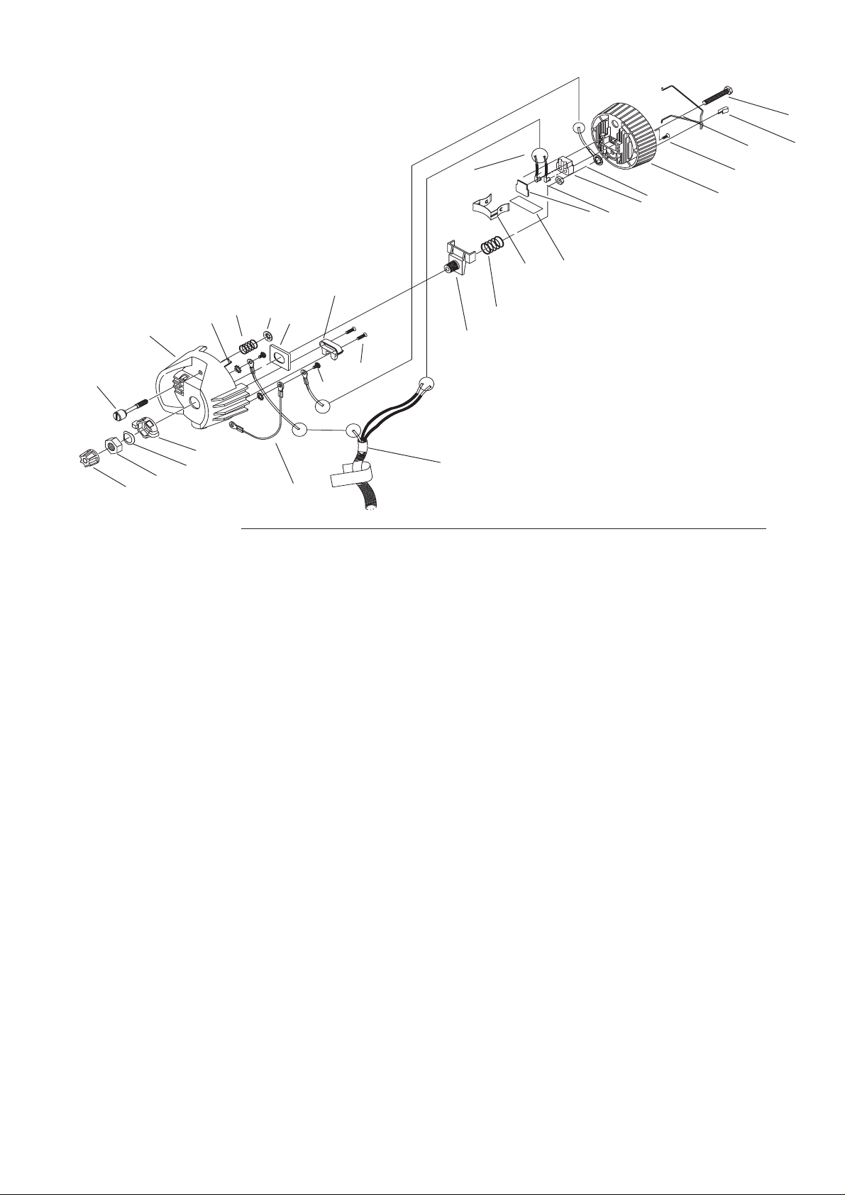
19
24
1
13
3
16
15
4
Lamp socket assembly
23
14
5
28
27
17
18
22
10
25
26
20
21
12
11
9
29
7
2
8
6
Reference Part Description Quantity
number number required
1 7060A3055 Housing, socket, casting, painted 1
2 7060A3057 Socket, light baffle casting, painted 1
3 7060A4007 Knob, X-Y, lamp set 1
4 7060A4008-02 Knob, Z, lamp set w/female insert 1
5 7060A4011 Bushing, cup 1
6 7060A3011 Hub, index, casting 1
7 7060A3012 Spring, lamp retainer 1
8 HW748 Spring, compression 1
9-11 M718 Complete TP22 450 degree-C CLCM assembly 1
9 W330-03 TP22 CLCM assembly, mica (1)
10 W330-04 TP22 CLCM 16-gauge, 1/4" semi-striped, Ni-gold contacts,
600V, 450˚C with 44" tails (2)
11 W330-02 TP22 CLCM assembly, ceramic (1)
12 HW534 Nut, hex, 1/4-20, black zinc 1
13 7060A3025 Screw, 1/4-20 knurled head 1
14 HW746 Retaining ring, flat, Southco 1
15 HW5123 Nut, hex, 9/16-18, black zinc 1
16 HW747 Washer, wave 1
17 7060A3056 Clamp, strain relief, painted 1
18 HW3103 Screw, 8-32 x 5/8 PhFHMS, black zinc 2
19 HW5122 Bolt, 1/4-20 x 1.75, full thread, black zinc 1
20 HW2125 Screw, self tap, 6-32 x 1/4, black zinc 1
21 7060B7014 Euro S4 ground wire 1
22 7060B7013 Euro S4 cable assembly 1
23 HW749 Spring, ground 1
24 HW349 Washer, ext. #8 1
25 7060A3085 Lamp retainer wire 1
26 HW8203 Lamp retainer Tinnerman clip 1
27 HW385 Screw, 8-32 x 3/8 PhPHMS 2
28 7060B7015 Safety wire assembly 1
29 I320 Kapton tape, 3/4" 1
4 Electronic Theatre Controls, Inc.
Page 5
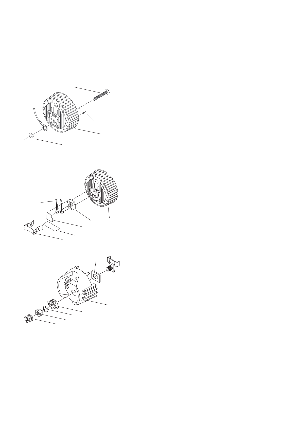
Figure 1
21
Lamp socket assembly
Tools required: Open-end adjustable wrench or a 7/16" socket,
needle-nose pliers, screwdriver.
1. Install the screw (20) into the light socket baffle casting as
19
20
shown in figure 1. (Also see figure 7 on page 7.)
2. Insert the bolt (19) through the light baffle socket casting (2).
3. Install the green ground wire assembly (21) on the bolt (19) with
the prongs on the crimped connector toward the casting. Run
the wire through the indent in the lip around the bolt hole.
Secure with nut (12) and torque to 60 inch pounds.
Figure 2
10
Figure 3
12
7
29
2
11
9
5
4. Place the Kapton tape (29) between the lamp retainer (7) and
the mica TP22 assembly (9) to hold the socket in place.
5. Place the ceramic TP22 socket (11) into the light baffle socket
casting (2) as shown in figure 2. Be sure it is well seated. Firmly
push the connectors on the white TP22 leads (10) into the
grooves in the socket.
6. Place the TP22 mica (9) over the leads, then install the lamp
retainer spring (7). The lamp retainer spring secures the mica.
Insert the spring one end at a time, making sure the rectangular
slot in each side of the spring seats on the corresponding tab in
the casting.
Important: If the spring does not seat correctly, coax it into
place with a screwdriver or needle-nose pliers.
2
7. Install the bushing cup (5) into the housing socket casting (1) as
shown in figure 3. The cup should slide smoothly up and down,
but not side to side.
8. Insert the threaded end of the index hub (6) through the holes in
the bushing cup and the back of the housing socket casting (1).
9. Slide the X-Y knob (3) over the exposed index hub bolt (6), then
insert the wave washer (16) on the bolt and secure with the 9/
16 hex nut (15). Hand tighten the X-Y knob (3).
6
Note: Install the wave washer with the upward curve toward
the hex nut.
1
3
16
15
4
CE Source Four jr / jr Zoom Assembly Guide 5
Page 6

Blue wire
w/sleeve
Figure 4
13
Figure 5
23
14
Green/yellow
wire
Brown wire
w/sleeve
9. Insert the knurled head screw (13) through the housing socket
casting (1) as shown in figure 4.
10. Install the ground spring (23) onto the screw and secure it with
the Southco flat retaining ring (14). Install the Southco ring with
its prongs away from the casting.
Note: Use pliers to straighten the Southco retaining ring (14) if it
bends when you install it on the bolt.
11. Lay the leads in the bottom half of the cable clamp, making sure
that the fiberglass sleeving extends slightly past the screw holes
in the housing socket casting, install new sleeving if necessary,
1
then route the wires as shown in figure 5.
Important: You must follow the wire routing diagram to ensure
that the socket leads do not interfere with the lamp focus
mechanism.
12. Install the top half of the cable clamp (17) and secure it with the
two screws (18) as shown in figure 6. Tighten the screws
alternately to ensure a solid connection.
Note: To ensure that the clamp holds the cable tightly, flatten
the cable, then fold over the sleeving before you install the top
half of the clamp. Make sure the top edge of the cable clamp is
even with the edge of the socket to prevent interference with
lamp focus movement. Make sure sleeving is not pinched.
Figure 6
13
Safety wire
4
Green/yellow
wire
1
3
6 (index hub)
17
18
19
12
2
8
6 Electronic Theatre Controls, Inc.
Page 7

13. Place the spring (8) on the protrusion on the inside of the index
hub (6).
14. Insert bolt (19) through the light socket baffle (2), thread nut
(12), through spring (8) and through the index hub (6) of the
housing socket (1), joining the two castings. Make sure wires are
not pinched between the two pieces.
15. Before proceeding, check again to make sure the wires are still
positioned as indicated in figure 5. Adjust if necessary.
16. Press the two castings together firmly so the bottom of the light
baffle (2) sits on top of the cable clamp (17), then install the X-Y
lampset (3) and Z lamp knob (4). Hand tighten the knob all the
way to the right.
Important: You must install Z knob as described above to ensure
proper lamp focus travel.
17. Set the crossbar of the retainer clip (25) under the two hooks on
the clip bracket as shown in figure 7.
18. Place the Tinnerman clip (26) over the retainer clip crossbar
between the two hooks and press it down firmly until it snaps
into place.
Figure 7
CE Source Four jr / jr Zoom Assembly Guide 7
Page 8

Lens holder assembly
Reference Part Description Quantity
number number required
1 7062A3005 Lens holder, 26° 1
2 7062A3017 Lens holder, 36° 1
3 7062A3018 Lens holder, 50° 1
4 7062A3019 Lens holder, Zoom, forward 1
5 7062A3020 Lens holder, Zoom, rear 1
6 7062A4001 Lens, 26°, “black dot” 1
7 7062A4002 Lens, 36°, “white dot” 1
8 7062A4003 Lens, 50°, “yellow dot” 1
9 7062A4008 Lens, Zoom, forward 1
10 7062A4009 Lens, Zoom, rear, black
11 7062A3027 Lens cover, Zoom, front, 25°– 50° 1
12 7062A3026 Lens cover, Zoom, rear, 25 °– 50° 1
13 HW751 Rivet, lens assembly 4
14 7060A4010 Bushing, gate
15 HW8209 Tinnerman clip 3
16 7062A1013 CE safety screen, Fixed field angle lens 1
17 HW4117 Nylon washer, flat, #10 2
18 HW779 Spring compression 2
19 HW8201 Lens knob, 10-32 x .50 LG male stud, black
20 7062A3029 Plate, secondary aperature 1
21 HW196 Nut 4-40 Keps 4
(mounted on rear side of lens holder)
rear lens 2
front lens 4
Zoom 2
Fixed field angle 1
7062A2001 Lens holder assembly, 26° (black) 1
7062A2003 Lens holder assembly, 36° (white) 1
7062A2004 Lens holder assembly, 50° (yellow) 1
7062A2005 Lens holder assembly, Zoom, forward 1
7062A2006 Lens holder assembly, Zoom, rear 1
8 Electronic Theatre Controls, Inc.
Page 9

Lens holder assembly
Fixed Field Angle Lens
1. Snap on the bushings (14).
2. Position the lens by centering the paint dot between the three
tabs, as shown below in figure 8.
2. Center one Tinnerman clip (15) on each tab, as shown in Figure
9, and press clip until it is fully seated. If clips are in uneven
positions, lens will be tilted or loose.
3. Firmly press each clip down and roll it away from the center of
the lens to ensure contact on lens surface.
4. Check lens and make sure the clips hold it securely.
5. Position safety screen as shown below, and secure with clips.
Fixed field angle lens assembly
Figure 8
1, 2, 3
15
16
Important:
Lens paint dot this side
6, 7, 8
14
17
18
19
CE Source Four jr / jr Zoom Assembly Guide 9
Page 10

11
Zoom Front Lens Assembly
1. Position the lens (9) between the lens holder (4) and the lens
cover (11) so that the convex side of the lens faces the lens
holder, as shown in Figure 9.
2. Align the holes in the lens cover with the holes in the lens holder
as shown below.
3. Secure the lens cover and the lens to the lens holder using
screws (14) and locking nuts (15). Tighten securely to ensure no
lens movement.
4. Snap the bushings (17) onto the lens holder assembly as shown.
Figure 9 4
9
19
Figure 10
Zoom Rear Lens Assembly
1. Slide spacers (16) over the PEM studs of the secondary
aperature plate (13), as shown in Figure 10.
2. Insert the PEM studs on the secondary aperature place (13)
through the holes in the lens holder (5).
3. Position the lens (10) between the lens holder (5) and lens cover
(12). The blue orientation marks on the lens should face towards
the lens holder.
4. Insert the PEM studs of the secondary aperature plate (13)
through the lens cover (12).
5. Secure the lens cover, lens, and aperature plate using nuts (15).
6. Snap bushings (17) to the lens holder (5).
5
10
21
12
20
10 Electronic Theatre Controls, Inc.
13
Page 11

Maintenance
Cleaning lenses
1. Dampen a clean, lint-free cloth with vinegar or household
ammonia. You may use water, but it will leave spots which may
be removed by polishing the lens gently with a clean, dry cloth.
Warning: Never use glass and window cleaner or any abrasive
material to clean the lens. Glass and window cleaners will stain
the lens surface. Abrasive materials (such as steel wool) will
damage the surface of the lens.
2. Starting from the center, gently wipe the lens.
Cleaning the reflector
Remove dust with a blast or oil-free air or wipe with a clean lint-free
cloth using alcohol or distilled water (alcohol is recommended).
Warning: Do not use glass and window cleaners on the reflector.
Chemicals in these cleaners wills tain the reflector.
CE Source Four jr / jr Zoom Assembly Guide 11
Page 12

1
3
4
Shutter assembly
Reference Part Description Quantity
number number required
1 7062A2002 Shutter blade assembly 4
2 7062A3016 Plate, divider 1
3 7062A3010 Plate, gate (middle) 1
4 7062A3030 Plate, divider with dimples 1
5 7062A3031 Plate, support, spring (see figure 12) 1
6 HW754 Spring, shutter (see figure 12) 4
2
12 Electronic Theatre Controls, Inc.
Page 13

Figure 11
Figure 12
Shutter assembly
Tools required: None
1. Place the bottom divider plate (2) on a flat surface.
Note: The notches on the divider plates must line up with each
1
3
4
2
other.
Warning: Divider plate edges are sharp. Handle with caution!
2. Place two shutter blades (1) on top of plate (2), handles facing
outward.
Note: Install shutter blades with the rounded sides facing the
same direction.
3. Place the middle divider plate (3) on top of the two shutter
blades.
4. Place the two remaining shutter blades (1) on top of the middle
divider plate.
Note: The third and fourth shutter blades should be at 90˚ angles
to the first and second.
5. Place the top divider plate (4) on top of the third and fourth
shutter blades.
6. Install the four springs (6) onto the nips on the spring plate
support (5).
7. Place the dimples of the plate divider (4) onto the open ends of
the springs.
5
6
CE Source Four jr / jr Zoom Assembly Guide 13
Page 14

20
21
12
19
13
9
1
17
18
23
24
25
10
11
14
4
3
7
6
2
5
26
27
8
15
9
4
16
22
Final assembly
ReferencePartDescriptionQuantity
numbernumberrequired
17062A3002Barrel, left casting1
27062A3004Barrel, right casting1
3See page 4Lamp burner assembly1
4HW8201Knob, 10-32 x .50 LG male stud, black1 or 2
57061A3005Clip, gel retainer1
67062A4010Reflector, jr, glass1
77062A3007Spring, round, reflector1
8HW750Spring, gel retainer1
9See page 8Lens holder assembly1 or 2
107062A3009Yoke, jr1
11HW8144Handle, yoke knob, 5/16-18, female1
12HW5193Bolt, hex 5/16-18 x 34 black zinc (yoke)2
13HW5125Bolt, carriage 5/16-181
14HW5126Washer, flat, 5/16, black oxide (yoke)3
15HW391Screw, PHMS, 8-32 x 3/4 LG.1
16See page 13Shutter assembly1
177062A3013Spring, reflector support2
18HW8200Retainer, push on2
197062A3014Light baffle strip1
207062A3015Cover, iris slot1
21HW372Screw, PhPHMS, 8-32 x 1/4 black oxide2
22HW3165 Screw, 8-32 x 1/2 PhPH TAPTITE 6
23 HW307 Screw, SPHMS, 8-32 x 3/8, black oxide 1
24 HW348 Washer, spt. #8 1
25 HW349 Washer, ext. #8 1
26 HW4117 Nylon washer, flat, #10 1 or 2
27 HW779 Spring compression 1 or 2
14Electronic Theatre Controls, Inc.
Page 15

Final assembly
Tools required: Phillips head screwdriver.
Note: Left and right designations are
your left and right as you look at the
front (gel plane) of the unit.
1. Place the left barrel casting (1) face up on your work surface with
the colorframe end to your right.
2. If necessary, place spring (17) over post in right and left castings
(1 and 2). Secure with the push-on retainer (18).
3. Set shutter assembly into the shutter slot in left casting (1) with
the rounded side of the shutter handles facing right.
4. Install the short end of the gel retainer clip (5) in the left lens
holder casting (1).
5. Position clip (5) in the forward, locked position, then install the
retainer spring (8) on the clip.
6. Snap spring (7) onto reflector (6) and place assembly into left
casting (1) so that the front edge of the reflector is supported by
spring (17) and the spring (7) on the back rests in the left casting
rear supports.
7. Gently set the right barrel casting (2) onto the left casting so that
the gel clip retainer, shutter assembly and reflector assembly fit
into their respective positions.
8. Starting with the corner nearest the gel clip retainer, attach the
right casting to the left casting with screws (22). Do the right
screws first, then the middle screws, then the left screws.
9. Install the iris slot cover (20) onto the barrel assembly with
screws (21).
10. With the colored dot on the lens facing out the barrel, slide the
lens holder assembly (or assemblies, if Zoom) into the lens
holder track inside the barrel. The assembly should slide
smoothly in the track.
11. Insert light baffle strip (19) through front of barrel assembly and
through hole in lens holder assembly. Slide strip (19) through
supports in front of fixture and install screw (15), spring (27),
washer (26), and knob (4).
12. Attach the lamp burner (3) to the barrel assembly with the
knurled head screw.
13. Attach yoke (10) to barrel assembly with bolts (12) and washers
(14). Attach yoke knob (11) with bolt (13) and washer (14).
Tighten bolts (12) to secure yoke to fixture.
CE Source Four jr / jr Zoom Assembly Guide 15
Page 16

Electronic Theatre Controls, Inc.
Americas
Europe London
Asia Hong Kong
Middleton, Wisconsin 53562 • USA • Tel: (+1) 608 831 4116 • Fax: (+1) 608 836 1736 • (+1) 800 775 4382 • service@etcconnect.com
• England • Tel: +44 (0)20 8896 1000 • Fax: +44 (0)20 8896 2000 • service@etceurope.com
• Tel: (+852) 2799 1220 • Fax: (+852) 2799 9325 • service@etcasia.com
International 3030 Laura Lane • Middleton, Wisconsin 53562 • USA • Tel: (+1) 608 831 4116 • Fax: (+1) 608 836 1736
World Wide Web http://www.etcconnect.com • Email mail@etcconnect.com
Copyright 2003. Specifications subject to change. Source Four jr™ and Source Four jr™ Zoom are protected by US patent numbers 5,268,613 and 5,446,637. International patents pending.
Revised 12/2003. 7062M1005 Rev. D
This document is the confidental property of ETC and is loaned subject to return upon demand. Title to this document is never sold or transferred for any reason. This document is to be used only pursuant to written license or
written instructions of ETC. All rights to designs and inventions are reserved by ETC. Possession of this document is subject to the foregoing.
 Loading...